
Review on Frontal Polymerization Behavior for Thermosetting Resins: Materials, Modeling and Application

Abstract
1. Introduction
2. Materials in FP
2.1. Resin Formulation
2.1.1. Resin
2.1.2. Initiators and Catalyst
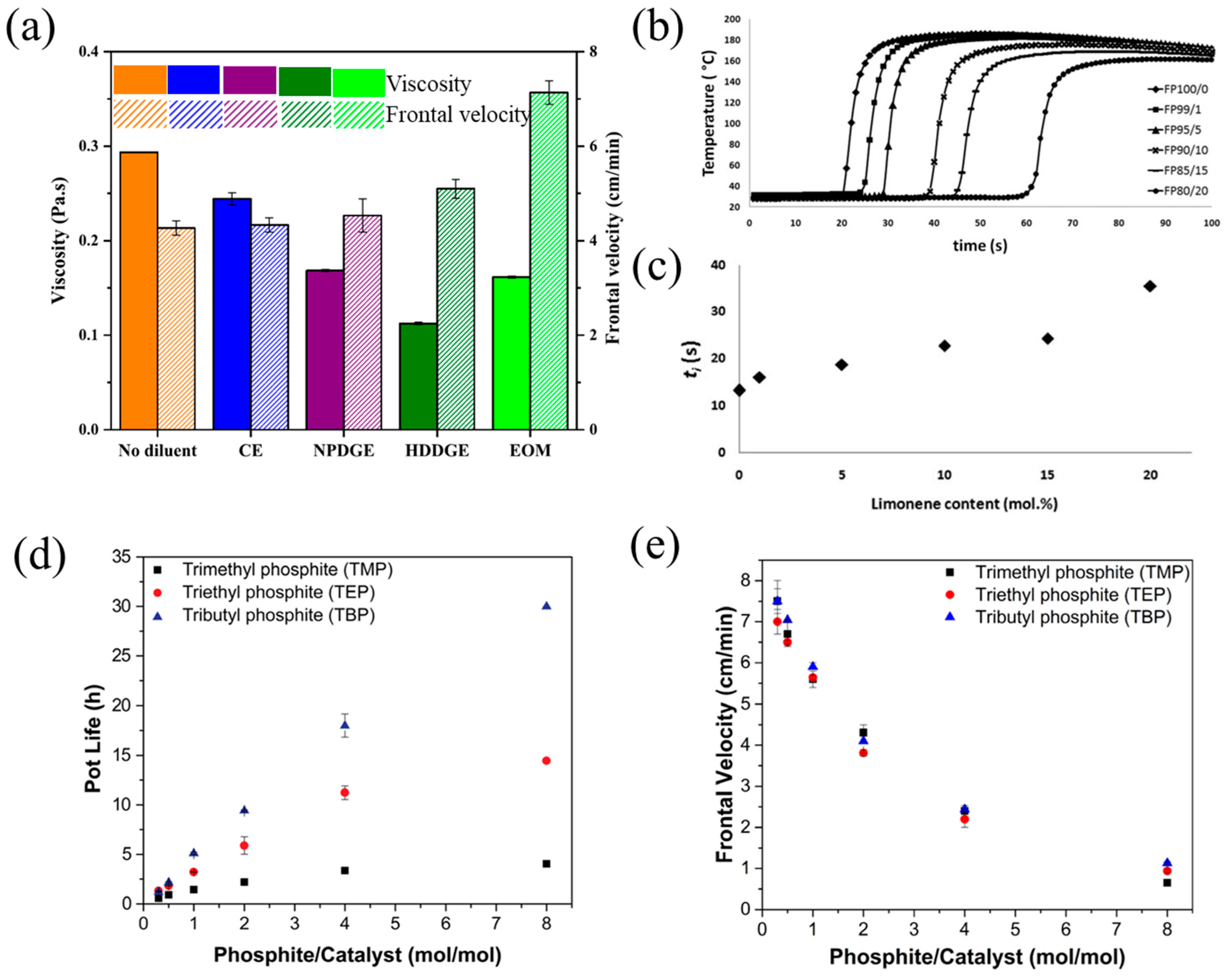
2.1.3. Diluents and Inhibitors
2.1.4. Photosensitizer
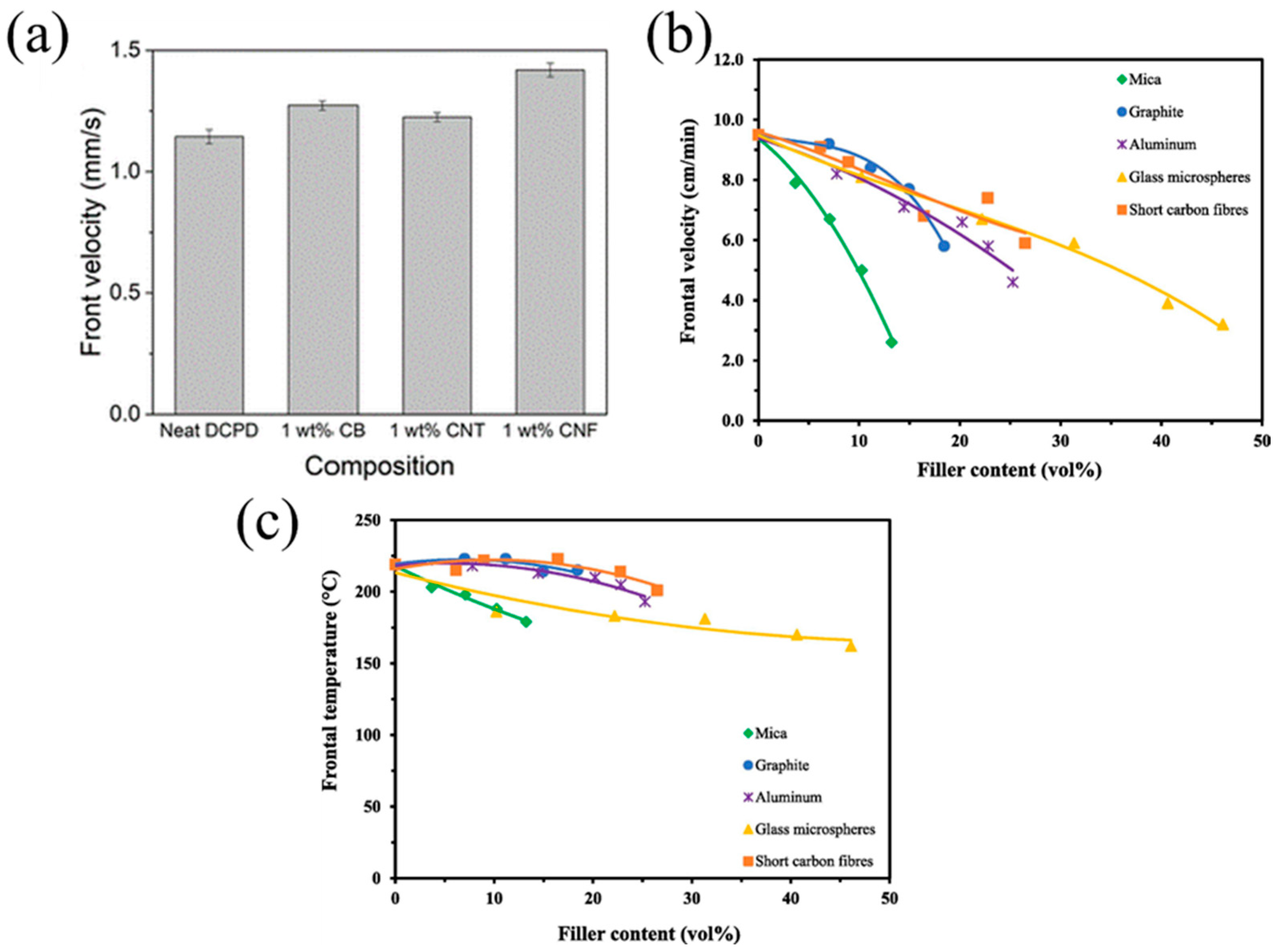
2.2. Fillers in Polymeric Composites
2.2.1. Discrete Fillers
2.2.2. Continuous Fibers
3. FP Modeling
3.1. The Basic Mathematical Model
3.2. Reaction-Thermal Transfer Model
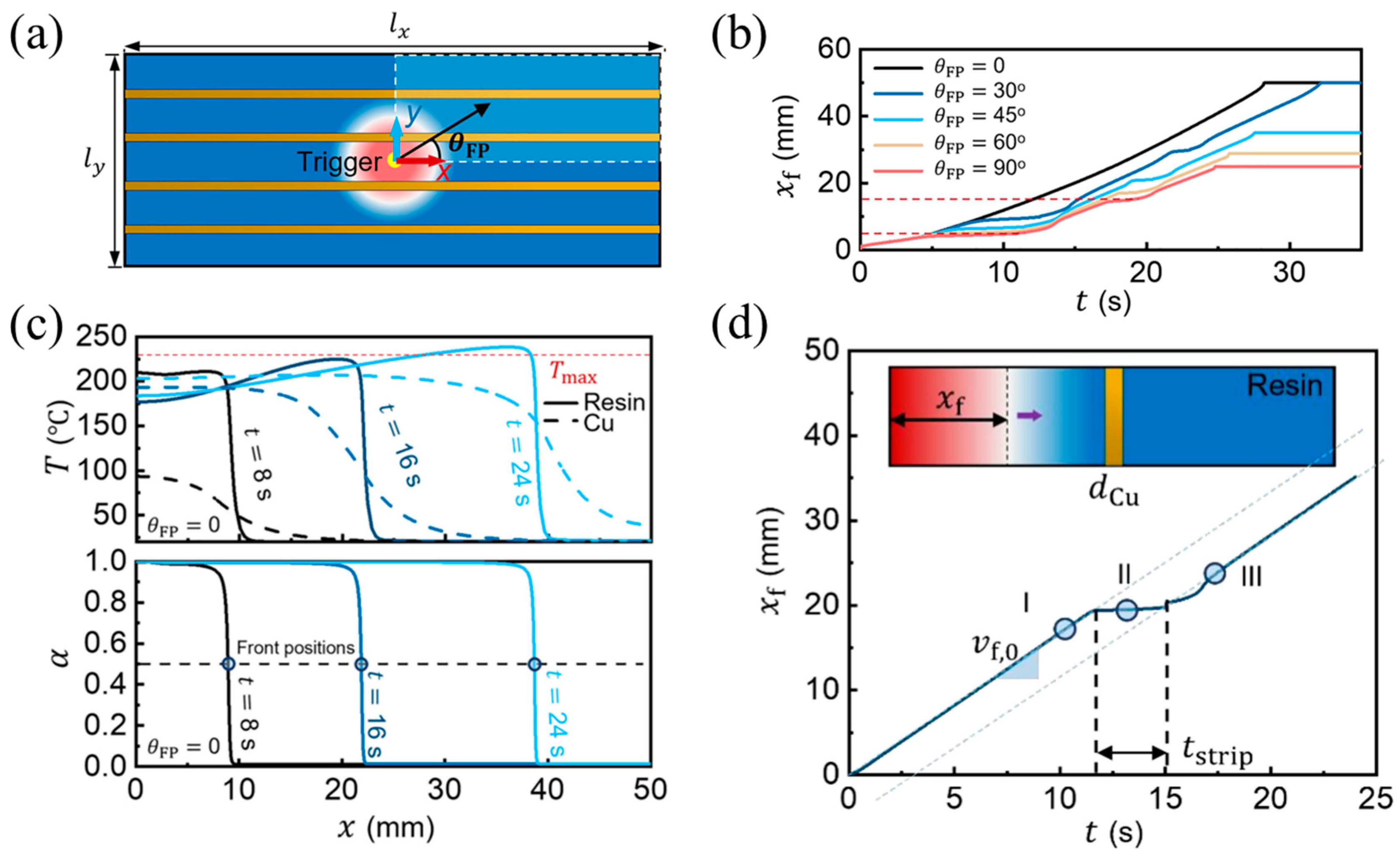
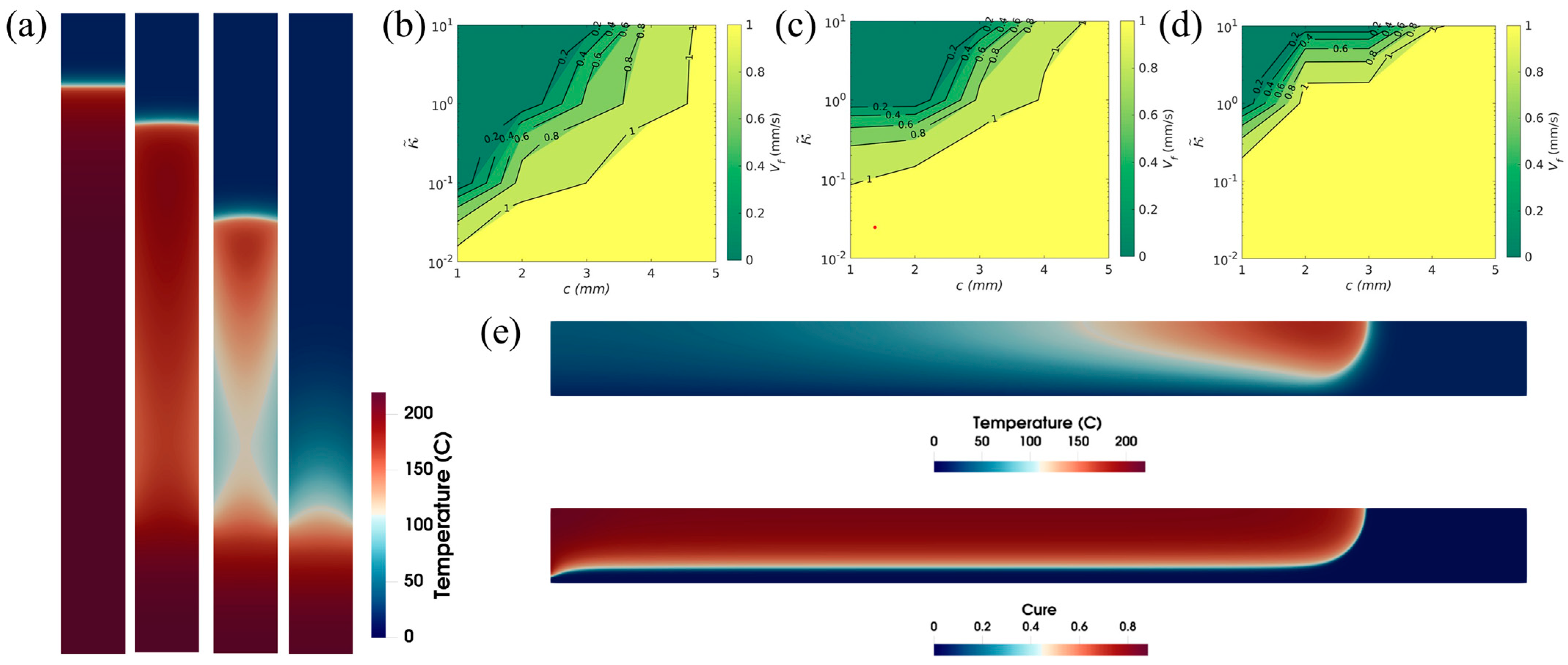
3.3. Numerical Study of Continuous Fiber Effect
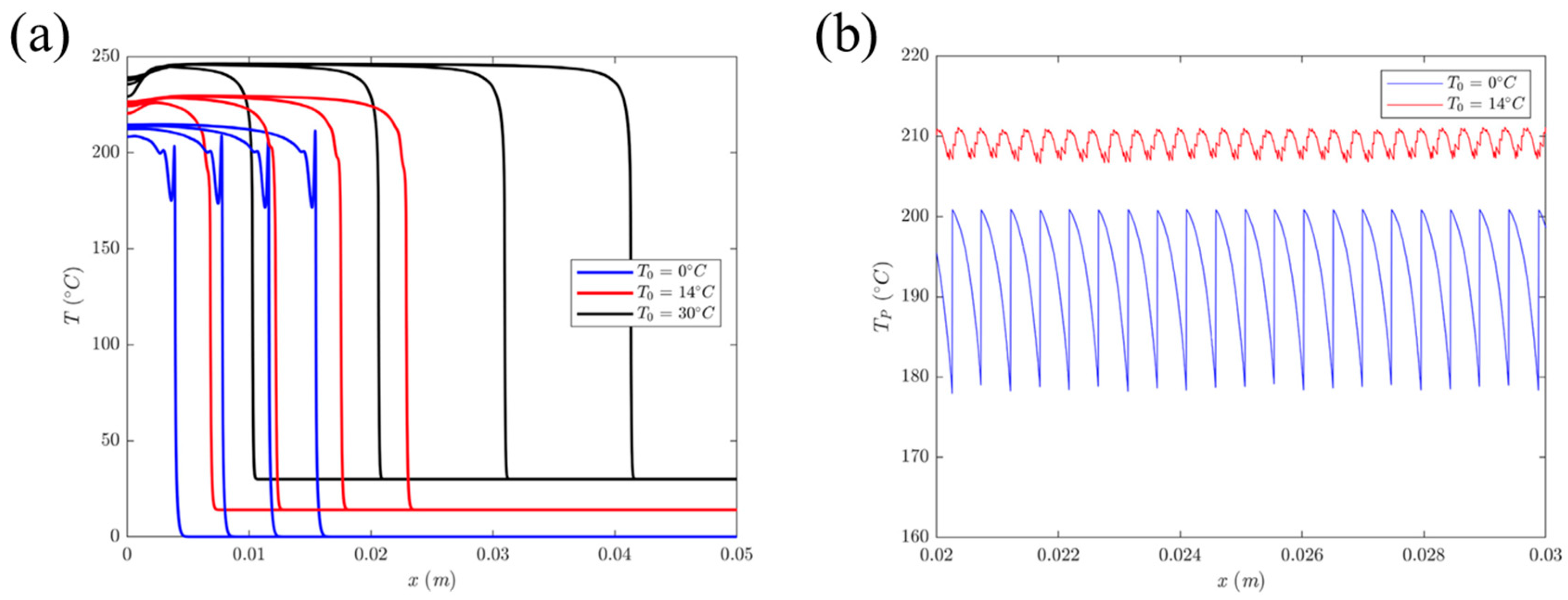
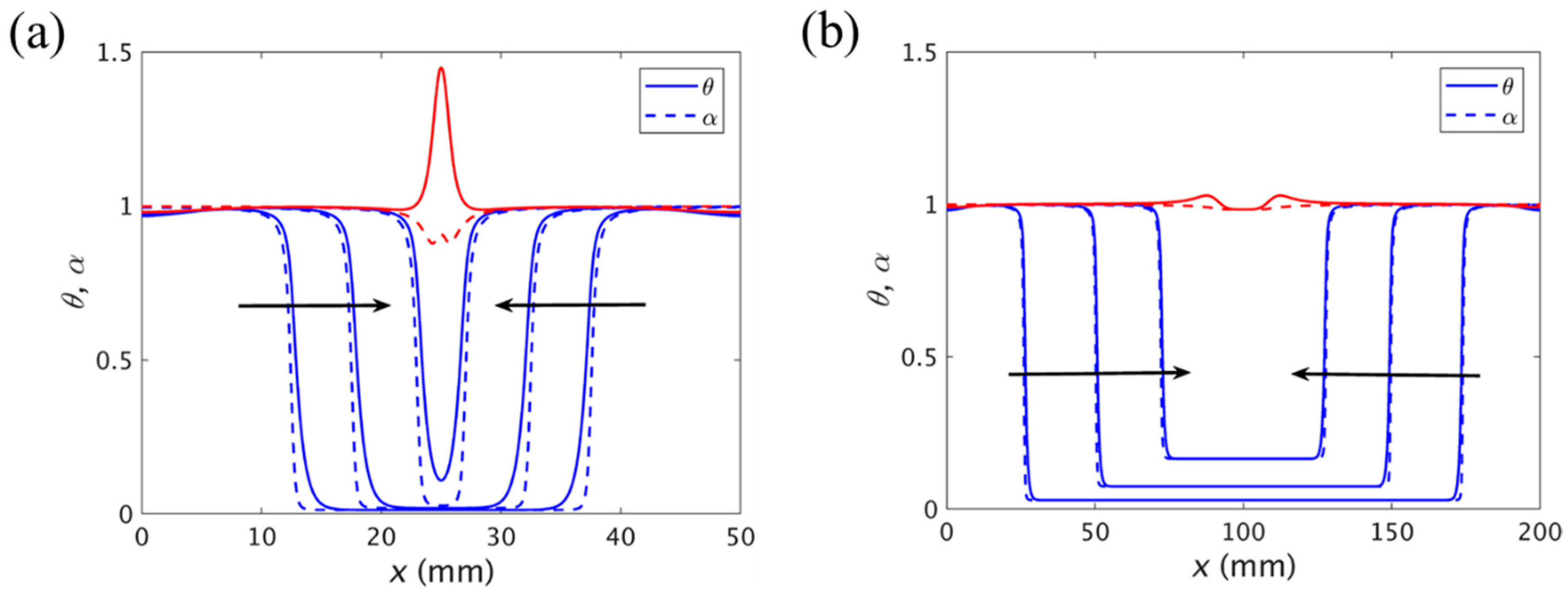
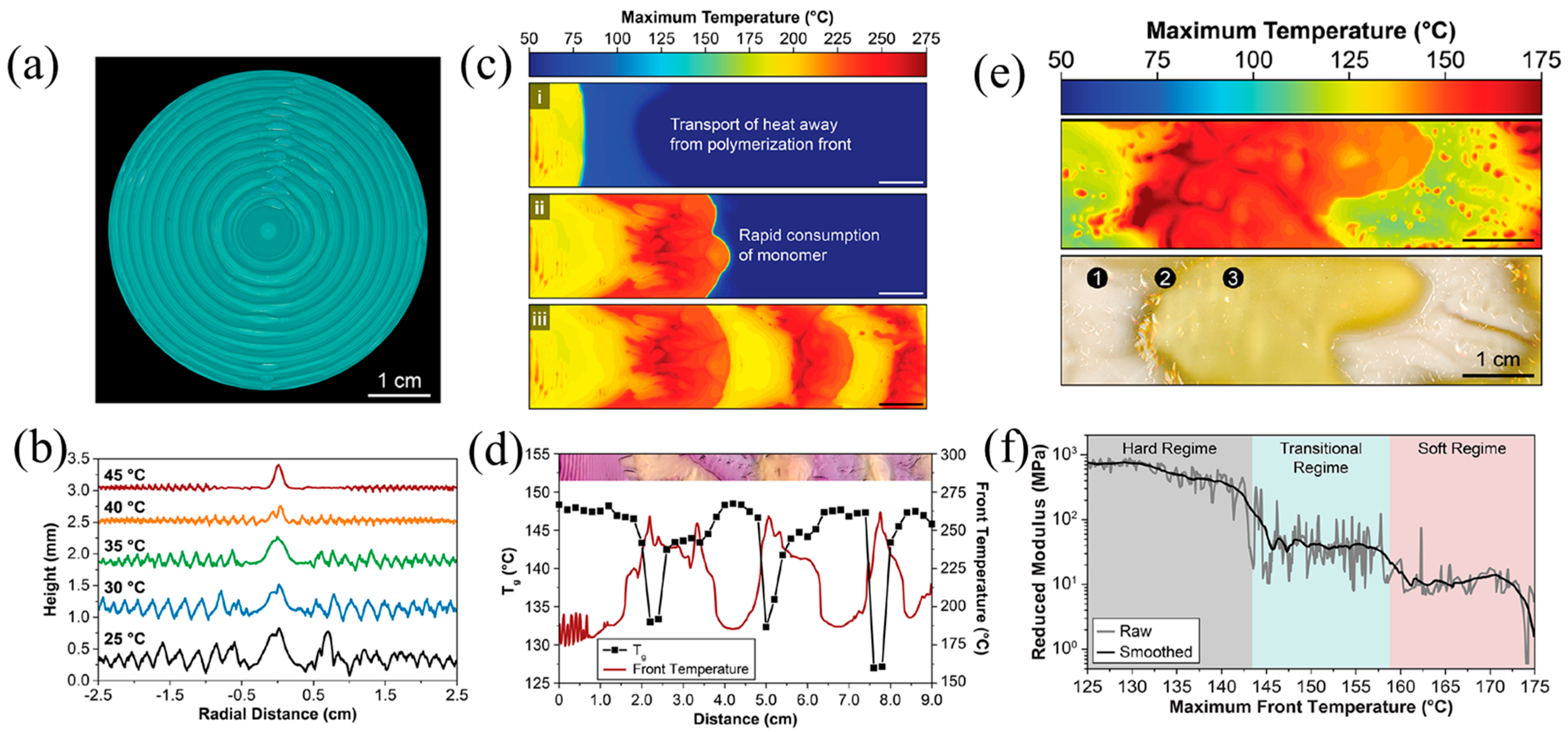
3.4. Numerical Work for Thermal Instability
4. FP Applications
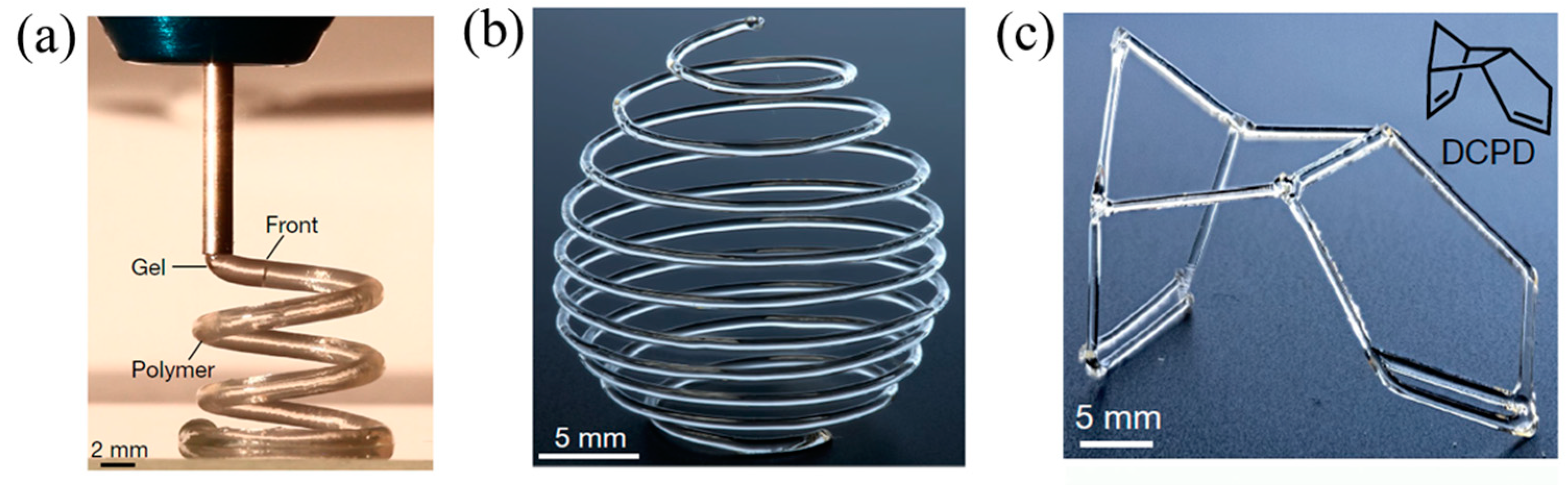
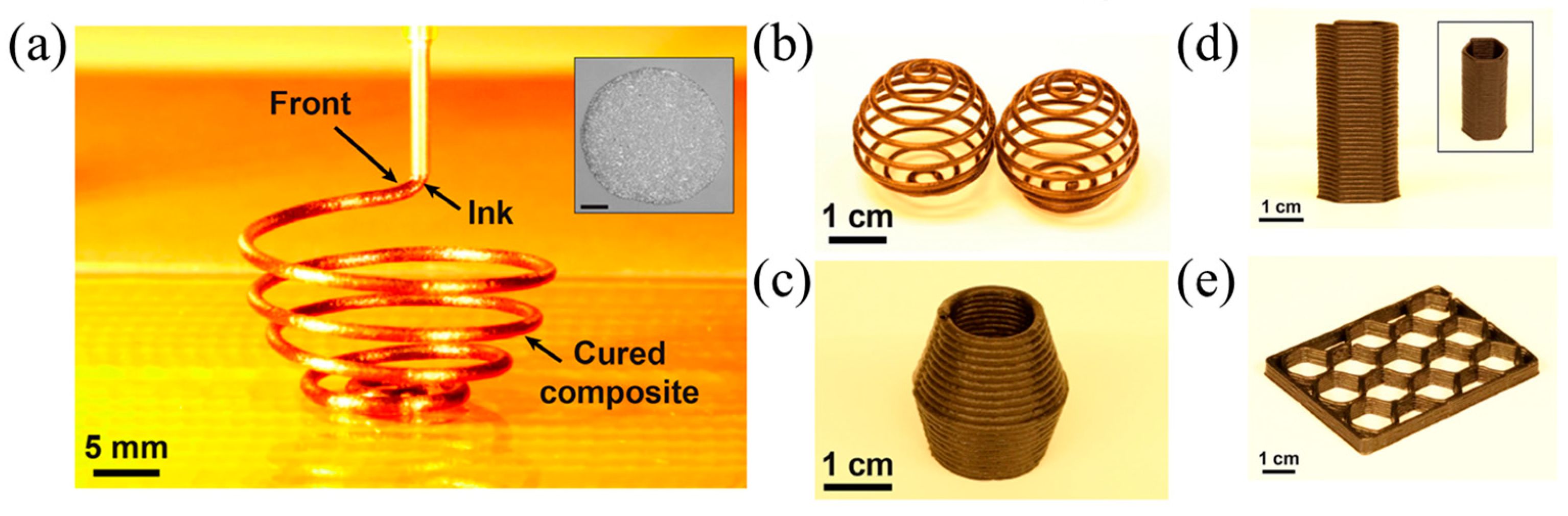
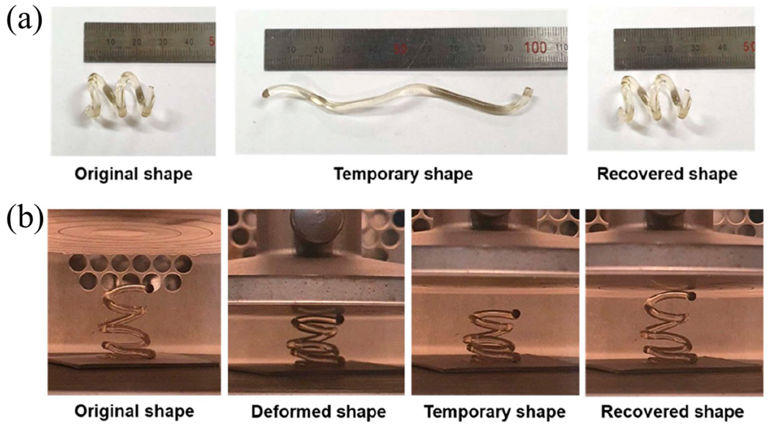
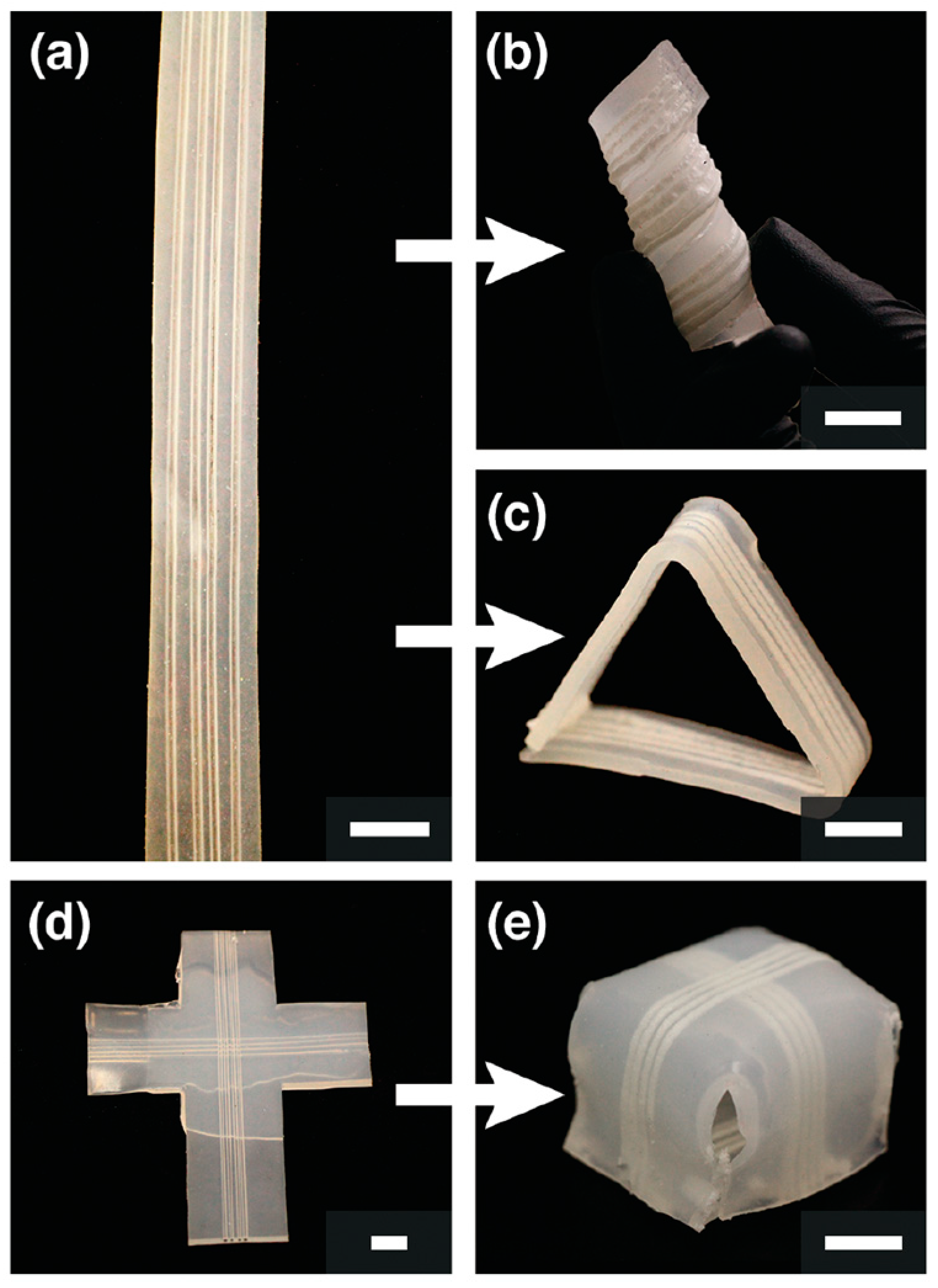
4.1. Free-Hanging Structure Using 3D Printing
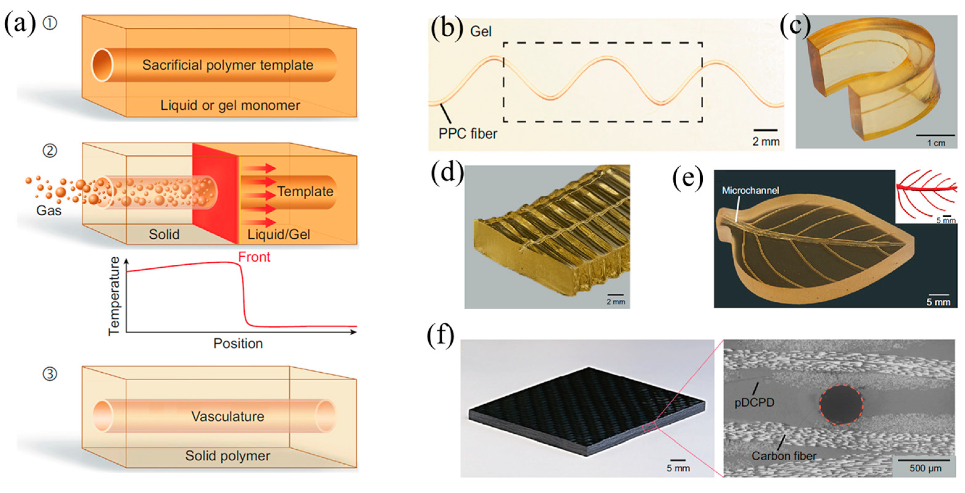
4.2. Bio-Inspired Structures
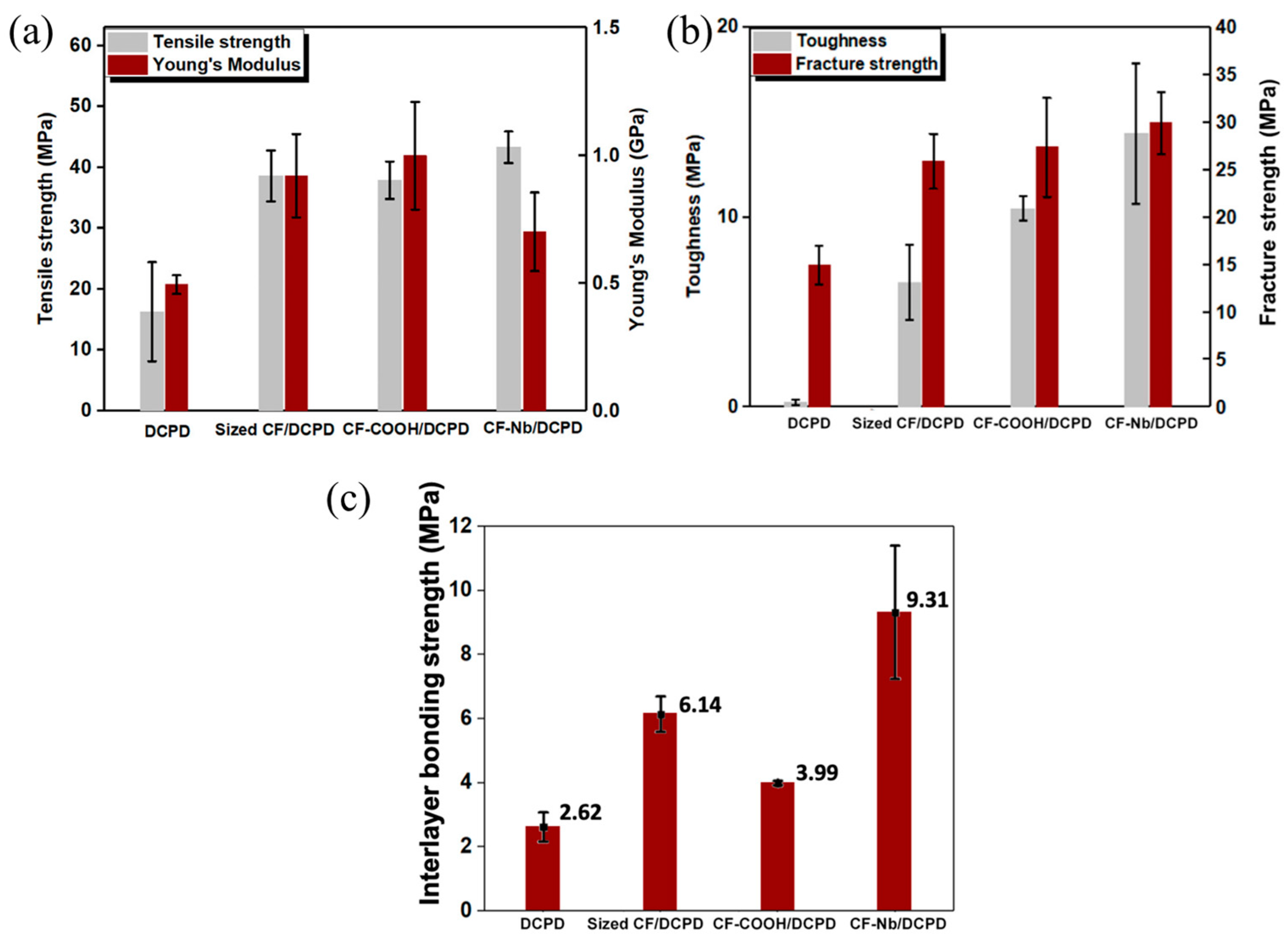
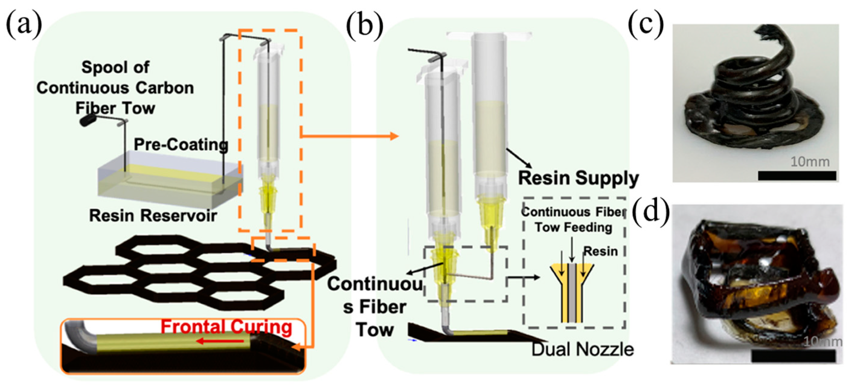
4.3. Fiber-Reinforced Composites
5. Conclusions and Future Roadmap
- (1)
- Currently, the majority of simulation studies on FP focus on continuous fillers, with fewer simulations addressing discrete fillers. It is crucial to conduct a simulation study on an FP with discrete fillers. Consequently, there is considerable potential for future development in simulating discrete fillers. This development could be valuable in designing and manufacturing materials with multifunctionality.
- (2)
- The composites prepared via FP have similar mechanical properties to those prepared via the traditional thermal curing method. Nevertheless, there is still the potential to improve the fiber volume fraction. Therefore, it is possible to obtain fiber-reinforced composites with higher performance by optimizing resin formulations, which enable the engineering applications of high-performance composites by FP.
- (3)
- At present, frontal characteristics such as frontal velocity, frontal temperature, and initiation time can be controlled by modifying the resin formulations. However, the effective stop of FP is still uncontrollable. Once an FP is triggered, a front propagates forward spontaneously until the uncured monomers are completely cured or are blocked by the boundary of mold. Therefore, effective and accurate control over the termination of FP in different directions and positions is desired to achieve ultimately complex structures with programming.
Author Contributions
Funding
Institutional Review Board Statement
Data Availability Statement
Conflicts of Interest
References
- Masuelli, M.A. Introduction of fibre-reinforced polymers−polymers and composites: Concepts, properties and processes. In Fiber Reinforced Polymers–The Technology Applied for Concrete Repair; IntechOpen: London, UK, 2013. [Google Scholar]
- Falzon, B.G.; Pierce, R.S. Thermosetting composite materials in aerostructures. In Revolutionizing Aircraft Materials and Processes; Springer: Berlin/Heidelberg, Germany, 2020; pp. 57–86. [Google Scholar]
- Balakrishnan, P.; John, M.J.; Pothen, L.; Sreekala, M.; Thomas, S. Natural fibre and polymer matrix composites and their applications in aerospace engineering. In Advanced Composite Materials for Aerospace Engineering; Elsevier: Amsterdam, The Netherlands, 2016; pp. 365–383. [Google Scholar]
- Thakur, V.K.; Thakur, M.K. Processing and characterization of natural cellulose fibers/thermoset polymer composites. Carbohyd. Polym. 2014, 109, 102–117. [Google Scholar] [CrossRef] [PubMed]
- Naik, N. Woven-fibre thermoset composites. In Fatigue in Composites: Science and Technology of the Fatigue Response of Fibre-reinforced Plastics; Elsevier: Amsterdam, The Netherlands, 2003; pp. 296–313. [Google Scholar]
- Marques, A. Fibrous materials reinforced composites production techniques. In Fibrous and Composite Materials for Civil Engineering Applications; Elsevier: Amsterdam, The Netherlands, 2011; pp. 191–215. [Google Scholar]
- Yarahmadi, E.; Didehban, K.; Sari, M.G.; Saeb, M.R.; Shabanian, M.; Aryanasab, F.; Zarrintaj, P.; Paran, S.M.R.; Mozafari, M.; Rallini, M. Development and curing potential of epoxy/starch-functionalized graphene oxide nanocomposite coatings. Prog. Org. Coat. 2018, 119, 194–202. [Google Scholar] [CrossRef]
- Tian, N.; Ning, R.; Kong, J. Self-toughening of epoxy resin through controlling topology of cross-linked networks. Polymer 2016, 99, 376–385. [Google Scholar] [CrossRef]
- Shah, D.B.; Patel, K.; Patel, A.I.; Pariyal, V.; Joshi, S.J. Experimental investigation on spring-back deformation during autoclave curing of parabolic antenna reflectors. Compos. Part. A-Appl. Sci. Manuf. 2018, 115, 134–146. [Google Scholar] [CrossRef]
- Pishvar, M.; Amirkhosravi, M.; Altan, M.C. Magnet assisted composite manufacturing: A novel fabrication technique for high-quality composite laminates. Polyme. Compos. 2019, 40, 159–169. [Google Scholar] [CrossRef]
- Li, Y.; Li, N.; Zhou, J.; Cheng, Q. Microwave curing of multidirectional carbon fiber reinforced polymer composites. Compos. Struct. 2019, 212, 83–93. [Google Scholar] [CrossRef]
- Kwak, M.; Robinson, P.; Bismarck, A.; Wise, R. Microwave curing of carbon–epoxy composites: Penetration depth and material characterisation. Compos. Part. A-Appl. Sci. Manuf. 2015, 75, 18–27. [Google Scholar] [CrossRef]
- Yang, G.; Luo, S.; Luo, B.; Zuo, Y.; Ta, S.; Lin, T.; Zhao, Z.; Zhang, Y.; Cui, C. The effects of pressure, temperature, and depth/diameter ratio on the microvia filling performance of Ag-coated Cu micro-nanoparticles for advanced electronic packaging. Int. J. Smart Nano Mater. 2022, 13, 543–560. [Google Scholar] [CrossRef]
- Yang, X.; Liu, J.; Wu, Y.; Liu, J.; Cheng, F.; Jiao, X.; Lai, G. Fabrication of UV-curable solvent-free epoxy modified silicone resin coating with high transparency and low volume shrinkage. Prog. Org. Coat. 2019, 129, 96–100. [Google Scholar] [CrossRef]
- Sangermano, M.; Razza, N.; Crivello, J.V. Cationic UV-curing: Technology and applications. Macromol. Mater. Eng. 2014, 299, 775–793. [Google Scholar] [CrossRef]
- Park, J.W.; Shim, G.S.; Lee, J.G.; Jang, S.W.; Kim, H.J.; Choi, J.N. Evaluation of UV curing properties of mixture systems with differently sized monomers. Materials 2018, 11, 509. [Google Scholar] [CrossRef] [PubMed]
- Lu, J.H.; Youngblood, J.P. Adhesive bonding of carbon fiber reinforced composite using UV-curing epoxy resin. Compos. Part B-Eng. 2015, 82, 221–225. [Google Scholar] [CrossRef]
- Austermann, J.; Redmann, A.J.; Dahmen, V.; Quintanilla, A.L.; Mecham, S.J.; Osswald, T.A. Fiber-reinforced composite sandwich structures by co-curing with additive manufactured epoxy lattices. J. Compos. Sci. 2019, 3, 53. [Google Scholar] [CrossRef]
- Pojman, J.A.; Ilyashenko, V.M.; Khan, A.M. Free-radical frontal polymerization: Self-propagating thermal reaction waves. J. Chem. Soc. Faraday Trans. 1996, 92, 2825–2837. [Google Scholar] [CrossRef]
- Chekanov, Y.; Arrington, D.; Brust, G.; Pojman, J.A. Frontal curing of epoxy resins: Comparison of mechanical and thermal properties to batch-cured materials. J. Appl. Polym. Sci. 1997, 66, 1209–1216. [Google Scholar] [CrossRef]
- Petko, F.; Świeży, A.; Ortyl, J. Photoinitiating systems and kinetics of frontal photopolymerization processes-the prospects for efficient preparation of composites and thick 3D structures. Polym. Chem. 2021, 12, 4593–4612. [Google Scholar] [CrossRef]
- Martínez-Serrano, R.D.; Ugone, V.; Porcu, P.; Vonlanthen, M.; Sorroza-Martínez, K.; Cuétara-Guadarrama, F.; Illescas, J.; Zhu, X.X.; Rivera, E. Novel porphyrin-containing hydrogels obtained by frontal polymerization: Synthesis, characterization and optical properties. Polymer 2022, 247, 124785. [Google Scholar] [CrossRef]
- Li, Q.; Shen, H.X.; Liu, C.; Wang, C.F.; Zhu, L.; Chen, S. Advances in Frontal Polymerization Strategy: From Fundamentals to Applications. Prog. Polym. Sci. 2022, 127, 101514. [Google Scholar] [CrossRef]
- Scognamillo, S.; Bounds, C.; Luger, M.; Mariani, A.; Pojman, J.A. Frontal cationic curing of epoxy resins. J. Polym. Sci. Polym. Chem. 2010, 48, 2000–2005. [Google Scholar] [CrossRef]
- Hu, G.; Fu, W.; Ma, Y.; Zhou, J.; Liang, H.; Kang, X.; Qi, X. Rapid Preparation of MWCNTs/Epoxy Resin Nanocomposites by Photoinduced Frontal Polymerization. Materials 2020, 13, 5838. [Google Scholar] [CrossRef]
- Arellano-Cruz, D.C.; Illescas, J.; Martínez-Gallegos, S.; Díaz-Nava, M.d.C. Synthesis and characterization of nanocomposites with nanocellulose obtained through frontal polymerization and study of their properties. MRS Adv. 2021, 6, 947–951. [Google Scholar] [CrossRef]
- Ziaee, M.; Yourdkhani, M. Effect of resin staging on frontal polymerization of dicyclopentadiene. J. Polym. Sci. 2021, 59, 1732–1739. [Google Scholar] [CrossRef]
- Chechilo, N.; NS, E.; RY, K. Phenomenon of polymerization reaction spreading. Dokl. Akad. Nauk. SSSR 1972, 204, 1180. [Google Scholar]
- Pojman, J.A. Traveling fronts of methacrylic acid polymerization. J. Am. Chem. Soc. 1991, 113, 6284–6286. [Google Scholar] [CrossRef]
- Pojman, J.A.; Willis, J.; Fortenberry, D.; Ilyashenko, V.; Khan, A.M. Factors affecting propagating fronts of addition polymerization: Velocity, front curvature, temperatue profile, conversion, and molecular weight distribution. J. Polym. Sci. Polym. Chem. 1995, 33, 643–652. [Google Scholar] [CrossRef]
- Pojman, J.A.; Ilyashenko, V.M.; Khan, A.M. Spin mode instabilities in propagating fronts of polymerization. Phys. D 1995, 84, 260–268. [Google Scholar] [CrossRef]
- Szalayl, J.; Nagy, I.P.; Barkai, I.; Zsuga, M. Conductive composites prepared via a propagating polymerization front. Die Angew. Makromol. Chem. 1996, 236, 97–109. [Google Scholar] [CrossRef]
- Nason, C.; Roper, T.; Hoyle, C.; Pojman, J.A. UV-Induced Frontal Polymerization of Multifunctional (Meth)acrylates. Macromolecules 2005, 38, 5506–5512. [Google Scholar] [CrossRef]
- Mariani, A.; Bidali, S.; Fiori, S.; Sangermano, M.; Malucelli, G.; Bongiovanni, R.; Priola, A. UV-ignited frontal polymerization of an epoxy resin. J. Polym. Sci. Polym. Chem. 2004, 42, 2066–2072. [Google Scholar] [CrossRef]
- Turani, M.; Baggio, A.; Casalegno, V.; Salvo, M.; Sangermano, M. An Epoxy Adhesive Crosslinked through Radical-Induced Cationic Frontal Polymerization. Macromol. Mater. Eng. 2021, 306, 2100495. [Google Scholar] [CrossRef]
- Švajdlenková, H.; Kleinová, A.; Šauša, O.; Rusnák, J.; Dung, T.A.; Koch, T.; Knaack, P. Microstructural study of epoxy-based thermosets prepared by “classical” and cationic frontal polymerization. RSC Adv. 2020, 10, 41098–41109. [Google Scholar] [CrossRef] [PubMed]
- Tran, A.D.; Koch, T.; Liska, R.; Knaack, P. Radical-induced cationic frontal polymerisation for prepreg technology. Monatshefte Für Chem.-Chem. Mon. 2021, 152, 151–165. [Google Scholar] [CrossRef]
- Sangermano, M. Recent advances in cationic photopolymerization. J. Photopolym. Sci. Tec. 2019, 32, 233–236. [Google Scholar] [CrossRef]
- Malik, M.S.; Schlögl, S.; Wolfahrt, M.; Sangermano, M. Review on UV-induced cationic frontal polymerization of epoxy monomers. Polymers 2020, 12, 2146. [Google Scholar] [CrossRef] [PubMed]
- Alzate-Sanchez, D.M.; Cencer, M.M.; Rogalski, M.; Kersh, M.; Sottos, N.; Moore, J.S. Anisotropic Foams Via Frontal Polymerization. Adv. Mater. 2021, 34, 2105821. [Google Scholar] [CrossRef] [PubMed]
- Mariani, A.; Fiori, S.; Chekanov, Y.; Pojman, J.A. Frontal ring-opening metathesis polymerization of dicyclopentadiene. Macromolecules 2001, 34, 6539–6541. [Google Scholar] [CrossRef]
- Kovačič, S.; Slugovc, C. Ring-opening Metathesis Polymerisation derived poly (dicyclopentadiene) based materials. Mater. Chem. Front. 2020, 4, 2235–2255. [Google Scholar] [CrossRef]
- Wang, P.; Yang, L.; Gao, S.; Chen, X.; Cao, T.; Wang, C.; Liu, H.; Hu, X.; Wu, X.; Feng, S. Enhanced dielectric properties of high glass transition temperature PDCPD/CNT composites by frontal ring-opening metathesis polymerization. Adv. Compos. Hybrid. Mater. 2021, 4, 639–646. [Google Scholar] [CrossRef]
- Suslick, B.A.; Stawiasz, K.J.; Paul, J.E.; Sottos, N.R.; Moore, J.S. Survey of catalysts for frontal ring-opening metathesis polymerization. Macromolecules 2021, 54, 5117–5123. [Google Scholar] [CrossRef]
- Robertson, I.D.; Yourdkhani, M.; Centellas, P.J.; Aw, J.E.; Ivanoff, D.G.; Goli, E.; Lloyd, E.M.; Dean, L.M.; Sottos, N.R.; Geubelle, P.H.; et al. Rapid energy-efficient manufacturing of polymers and composites via frontal polymerization. Nature 2018, 557, 223–227. [Google Scholar] [CrossRef]
- Davtyan, S.; Tonoyan, A. The frontal polymerization method in high technology applications. Rev. J. Chem. 2019, 9, 71–94. [Google Scholar] [CrossRef]
- Gachet, B.; Lecompère, M.; Croutxé-Barghorn, C.; Burr, D.; L’Hostis, G.; Allonas, X. Highly reactive photothermal initiating system based on sulfonium salts for the photoinduced thermal frontal cationic polymerization of epoxides: A way to create carbon-fiber reinforced polymers. RSC. Adv. 2020, 10, 41915–41920. [Google Scholar] [CrossRef] [PubMed]
- Alzate-Sanchez, D.M.; Yu, C.H.; Lessard, J.J.; Paul, J.E.; Sottos, N.R.; Moore, J.S. Rapid Controlled Synthesis of Large Polymers by Frontal Ring-Opening Metathesis Polymerization. Macromolecules 2023, 56, 1527–1533. [Google Scholar] [CrossRef]
- Noè, C.; Hakkarainen, M.; Malburet, S.; Graillot, A.; Adekunle, K.; Skrifvars, M.; Sangermano, M. Frontal-photopolymerization of Fully Biobased Epoxy Composites. Macromol. Mater. Eng. 2022, 307, 2100864. [Google Scholar] [CrossRef]
- Wu, Q.; Ding, D.; Wang, J.; Zhi, C. Rapid Fabrication of Flexible Polymer/CNT Nanocomposites for Thermoelectric Power Generation. Power SSRA 2022. [Google Scholar] [CrossRef]
- Kumar, A.; Gao, Y.; Geubelle, P.H. Analytical estimates of front velocity in the frontal polymerization of thermoset polymers and composites. J. Polym. Sci. 2021, 59, 1109–1118. [Google Scholar] [CrossRef]
- Pojman, J.A. Frontal Polymerization. In Polymer Science: A Comprehensive Reference; Matyjaszewski, K., Möller, M., Eds.; Elsevier: Amsterdam, The Netherlands, 2012; pp. 957–980. [Google Scholar]
- González-Henríquez, C.; Vallejos, S.; Rodríguez-Hernández, J. Wrinkles obtained by frontal polymerization/vitrification. In Wrinkled Polymer Surfaces; Springer: Berlin/Heidelberg, Germany, 2019; pp. 63–84. [Google Scholar]
- Gao, Y.; Dearborn, M.A.; Hemmer, J.; Wang, Z.; Esser-Kahn, A.P.; Geubelle, P.H. Controllable Frontal Polymerization and Spontaneous Patterning Enabled by Phase-Changing Particles. Small 2021, 17, 2102217. [Google Scholar] [CrossRef]
- Gao, Y.; Dearborn, M.A.; Vyas, S.; Kumar, A.; Hemmer, J.; Wang, Z.; Wu, Q.; Alshangiti, O.; Moore, J.S.; Esser-Kahn, A.P.; et al. Manipulating Frontal Polymerization and Instabilities with Phase-Changing Microparticles. J. Phys. Chem. B 2021, 125, 7537–7545. [Google Scholar] [CrossRef]
- Lloyd, E.M.; Feinberg, E.C.; Gao, Y.; Peterson, S.R.; Soman, B.; Hemmer, J.; Dean, L.M.; Wu, Q.; Geubelle, P.H.; Sottos, N.R.; et al. Spontaneous Patterning during Frontal Polymerization. ACS. Cent. Sci. 2021, 7, 603–612. [Google Scholar] [CrossRef]
- Bomze, D.; Knaack, P.; Liska, R. Successful radical induced cationic frontal polymerization of epoxy-based monomers by C–C labile compounds. Polym. Chem. 2015, 6, 8161–8167. [Google Scholar] [CrossRef]
- Bomze, D.; Knaack, P.; Koch, T.; Jin, H.; Liska, R. Radical induced cationic frontal polymerization as a versatile tool for epoxy curing and composite production. J. Polym. Sci. Part A Polym. Chem. 2016, 54, 3751–3759. [Google Scholar] [CrossRef]
- Taschner, R.; Knaack, P.; Liska, R. Bismuthonium- and pyrylium-based radical induced cationic frontal polymerization of epoxides. J. Polym. Sci. 2021, 59, 1841–1854. [Google Scholar] [CrossRef]
- Knaack, P.; Klikovits, N.; Tran, A.D.; Bomze, D.; Liska, R. Radical induced cationic frontal polymerization in thin layers. J. Polym. Sci. Polym. Chem. 2019, 57, 1155–1159. [Google Scholar] [CrossRef]
- Maugeri, D.; Sangermano, M.; Leterrier, Y. Radical photoinduced cationic frontal polymerization in porous media. Polym. Int. 2020, 70, 269–276. [Google Scholar] [CrossRef]
- Tran, A.D.; Koch, T.; Knaack, P.; Liska, R. Radical induced cationic frontal polymerization for preparation of epoxy composites. Compos. Part A Appl. Sci. Manuf. 2020, 132, 105855. [Google Scholar] [CrossRef]
- Malik, M.S.; Wolfahrt, M.; Sangermano, M.; Schlögl, S. Effect of a Dicycloaliphatic Epoxide on the Thermo-Mechanical Properties of Alkyl, Aryl Epoxide Monomers Cured via UV-Induced Cationic Frontal Polymerization. Macromol. Mater. Eng. 2022, 307, 2100976. [Google Scholar] [CrossRef]
- Klikovits, N.; Liska, R.; D’Anna, A.; Sangermano, M. Successful UV-Induced RICFP of Epoxy-Composites. Macromol. Chem. Phys. 2017, 218, 1700313. [Google Scholar] [CrossRef]
- Xin, Y.; Xiao, S.; Pang, Y.; Zou, Y. NIR-sensitized cationic frontal polymerization of vinyl ether and epoxy monomers. Prog. Org. Coat. 2021, 153, 106149. [Google Scholar] [CrossRef]
- Robertson, I.D.; Pruitt, E.L.; Moore, J.S. Frontal Ring-Opening Metathesis Polymerization of Exo-Dicyclopentadiene for Low Catalyst Loadings. ACS. Macro Lett. 2016, 5, 593–596. [Google Scholar] [CrossRef]
- Dean, L.M.; Wu, Q.; Alshangiti, O.; Moore, J.S.; Sottos, N.R. Rapid Synthesis of Elastomers and Thermosets with Tunable Thermomechanical Properties. ACS. Macro Lett. 2020, 9, 819–824. [Google Scholar] [CrossRef]
- Liu, H.; Wei, H.; Moore, J.S. Frontal Ring-Opening Metathesis Copolymerization: Deviation of Front Velocity from Mixing Rules. ACS. Macro Lett. 2019, 8, 846–851. [Google Scholar] [CrossRef] [PubMed]
- Ruiu, A.; Sanna, D.; Alzari, V.; Nuvoli, D.; Mariani, A. Advances in the frontal ring opening metathesis polymerization of dicyclopentadiene. J. Polym. Sci. Polym. Chem. 2014, 52, 2776–2780. [Google Scholar] [CrossRef]
- Ivanoff, D.G.; Sung, J.; Butikofer, S.M.; Moore, J.S.; Sottos, N.R. Cross-Linking Agents for Enhanced Performance of Thermosets Prepared via Frontal Ring-Opening Metathesis Polymerization. Macromolecules 2020, 53, 8360–8366. [Google Scholar] [CrossRef]
- Stawiasz, K.J.; Paul, J.E.; Schwarz, K.J.; Sottos, N.R.; Moore, J.S. Photoexcitation of Grubbs’ Second-Generation Catalyst Initiates Frontal Ring-Opening Metathesis Polymerization. ACS Macro Lett. 2020, 9, 1563–1568. [Google Scholar] [CrossRef] [PubMed]
- Alzari, V.; Nuvoli, D.; Sanna, D.; Ruiu, A.; Mariani, A. Effect of limonene on the frontal ring opening metathesis polymerization of dicyclopentadiene. J. Polym. Sci. Polym. Chem. 2016, 54, 63–68. [Google Scholar] [CrossRef]
- Robertson, I.D.; Dean, L.M.; Rudebusch, G.E.; Sottos, N.R.; White, S.R.; Moore, J.S. Alkyl Phosphite Inhibitors for Frontal Ring-Opening Metathesis Polymerization Greatly Increase Pot Life. ACS. Macro. Lett. 2017, 6, 609–612. [Google Scholar] [CrossRef]
- Dean, L.M.; Ravindra, A.; Guo, A.X.; Yourdkhani, M.; Sottos, N.R. Photothermal Initiation of Frontal Polymerization Using Carbon Nanoparticles. ACS Appl. Polym. Mater. 2020, 2, 4690–4696. [Google Scholar] [CrossRef]
- Birkner, M.; Seifert, A.; Spange, S. Radical induced cationic frontal twin polymerization of Si-spiro compound in combination with bisphenol-A-diglycidylether. Polymer 2018, 160, 19–23. [Google Scholar] [CrossRef]
- Luo, T.; Fu, K.; Zhu, H.; Chen, Y.; Yang, B.; Li, Y. In-plane and in-depth frontal polymerization behaviors of continuous fiber-reinforced epoxy composites. Polym. Compos. 2023, 1–13. [Google Scholar] [CrossRef]
- Vyas, S.; Goli, E.; Zhang, X.; Geubelle, P.H. Manufacturing of unidirectional glass-fiber-reinforced composites via frontal polymerization: A numerical study. Compos. Sci. Technol. 2019, 184, 107832. [Google Scholar] [CrossRef]
- Klikovits, N.; Knaack, P.; Bomze, D.; Krossing, I.; Liska, R. Novel photoacid generators for cationic photopolymerization. Polym. Chem. 2017, 8, 4414–4421. [Google Scholar] [CrossRef]
- Farcet, C.; Lansalot, M.; Charleux, B.; Pirri, R.; Vairon, J. Mechanistic aspects of nitroxide-mediated controlled radical polymerization of styrene in miniemulsion, using a water-soluble radical initiator. Macromolecules 2000, 33, 8559–8570. [Google Scholar] [CrossRef]
- Dauletov, Y.; Abdiyev, K.; Toktarbay, Z.; Nuraje, N.; Zhursumbaeva, M.; Kenzhaliyev, B. Radical polymerization and kinetics of N, N-diallyl-N, N-dimethylammonium chloride and vinyl ether of monoethanolamine. Fiber. Polym. 2018, 19, 2023–2029. [Google Scholar] [CrossRef]
- Groce, B.R.; Gary, D.P.; Cantrell, J.K.; Pojman, J.A. Front velocity dependence on vinyl ether and initiator concentration in radical induced cationic frontal polymerization of epoxies. J. Polym. Sci. 2021, 59, 1679–1685. [Google Scholar] [CrossRef]
- Crivello, J.V.; Bulut, U. Photoactivated cationic ring-opening frontal polymerizations of oxetanes. Des. Monomers Polym. 2005, 8, 517–531. [Google Scholar] [CrossRef]
- Bulut, U.; Crivello, J.V. Reactivity of oxetane monomers in photoinitiated cationic polymerization. J. Polym. Sci. Polym. Chem. 2005, 43, 3205–3220. [Google Scholar] [CrossRef]
- Crivello, J.V. Redox initiated cationic polymerization of oxetanes. J. Polym. Sci. Part A Polym. Chem. 2015, 53, 1854–1861. [Google Scholar] [CrossRef]
- McFarland, B.; Popwell, S.; Pojman, J.A. Free-Radical Frontal Polymerization with a Microencapsulated Initiator: Characterization of Microcapsules and Their Effect on Pot Life, Front Velocity, and Mechanical Properties. Macromolecules 2006, 39, 55–63. [Google Scholar] [CrossRef]
- Davydovich, O.; GreenleeA, J.G.; Root, H.D.; Jansen, A.L.; Gallegos, S.C.; Warner, M.J.; Kent, M.S.; Cardenas, J.A.; Appelhans, L.N.; Roach, D.J.; et al. Encapsulated Transition Metal Catalysts Enable Long-term Stability in Frontal Polymerization Resins. Macromolecules 2023, 56, 7543–7550. [Google Scholar] [CrossRef]
- Egen, N.; Krause, R. Iodonium salts of complex anions. IV. Autophenylation of diphenyliodonium trans-dicyanobis (dimethylglyoximato) cobaltate (III). Inorg. Chem. 1972, 11, 1327–1331. [Google Scholar] [CrossRef]
- Müller, U.; Utterodt, A.; Mörke, W.; Deubzer, B.; Herzig, C. New insights about diazonium salts as cationic photoinitiators. J. Photoch. Photobio. A. 2001, 140, 53–66. [Google Scholar] [CrossRef]
- Gronheid, R.; Lodder, G.; Okuyama, T. Photosolvolysis of (E)-styryl (phenyl) iodonium tetrafluoroborate. Generation and reactivity of a primary vinyl cation. J. Org. Chem. 2002, 67, 693–702. [Google Scholar] [CrossRef] [PubMed]
- Yagci, Y.; Hepuzer, Y. A novel visible light initiatiating system for cationic polymerization. Macromolecules 1999, 32, 6367–6370. [Google Scholar] [CrossRef]
- Crivello, J.V.; Jiang, F. Development of pyrene photosensitizers for cationic photopolymerizations. Chem. Mater. 2002, 14, 4858–4866. [Google Scholar] [CrossRef]
- Telitel, S.; Blanchard, N.; Schweizer, S.; Morlet-Savary, F.; Graff, B.; Fouassier, J.-P.; Lalevée, J. BODIPY derivatives and boranil as new photoinitiating systems of cationic polymerization exhibiting a tunable absorption in the 400–600 nm spectral range. Polymer 2013, 54, 2071–2076. [Google Scholar] [CrossRef]
- Corrêa, R.S.; Barolli, J.P.; Ribeiro, L.; Batista, A.A.; Ellena, J.; Andrade, M.B. Experimental and theoretical investigation of molecular structure and conformation of the 4-isopropylthioxanthone. J. Mol. Struct. 2011, 1000, 155–161. [Google Scholar] [CrossRef]
- Alvino, A.; Franceschin, M.; Cefaro, C.; Borioni, S.; Ortaggi, G.; Bianco, A. Synthesis and spectroscopic properties of highly water-soluble perylene derivatives. Tetrahedron 2007, 63, 7858–7865. [Google Scholar] [CrossRef]
- Castellanosa, E.M.; Delgadob, A.E.; Sinhoretic, M.A.; de Oliveira DC, R.S.; Abdulhameed, N.; Geraldeli, S.; Roulet, J.F. Effect of Thickness of Ceramic Veneers on Color Stability and Bond Strength of Resin Luting Cements Containing Alternative Photoinitiators. J. Adhes. Den. 2019, 21, 67–76. [Google Scholar]
- Scognamillo, S.; Bounds, C.; Thakuri, S.; Mariani, A.; Wu, Q.; Pojman, J.A. Frontal cationic curing of epoxy resins in the presence of defoaming or expanding compounds. J. Appl. Polym. Sci. 2014, 131, 40339–40350. [Google Scholar] [CrossRef]
- Gao, Y.; Shaon, F.; Kumar, A.; Bynum, S.; Gary, D.; Sharp, D.; Pojman, J.A.; Geubelle, P.H. Rapid frontal polymerization achieved with thermally conductive metal strips. Chaos 2021, 31, 073113. [Google Scholar] [CrossRef]
- Goli, E.; Robertson, I.D.; Agarwal, H.; Pruitt, E.L.; Grolman, J.M.; Geubelle, P.H.; Moore, J.S. Frontal polymerization accelerated by continuous conductive elements. J. Appl. Polym. Sci. 2018, 136, 47418–47427. [Google Scholar] [CrossRef]
- Sangermano, M.; Antonazzo, I.; Sisca, L.; Carello, M. Photoinduced cationic frontal polymerization of epoxy–carbon fibre composites. Polym. Int. 2019, 68, 1662–1665. [Google Scholar] [CrossRef]
- Goldfeder, P.; Volpert, V.A.; Ilyashenko, V.; Khan, A.; Pojman, J.; Solovyov, S. Mathematical modeling of free-radical polymerization fronts. J. Phys. Chem. B 1997, 101, 3474–3482. [Google Scholar] [CrossRef]
- Goldfeder, P.; Volpert, V. Nonadiabatic frontal polymerization. J. Eng. Math. 1998, 34, 301–318. [Google Scholar] [CrossRef]
- Comissiong, D.; Gross, L.; Volpert, V. Nonlinear dynamics of frontal polymerization with autoacceleration. J. Eng. Math. 2005, 53, 59–78. [Google Scholar] [CrossRef][Green Version]
- Comissiong, D.; Gross, L.; Volpert, V. Frontal polymerization in the presence of an inert material. J. Eng. Math. 2006, 54, 389–402. [Google Scholar] [CrossRef]
- Jimada, A.; Olayiwola, R.; Shehu, M.D.; Cole, A.; Mohammed, A. Modeling and analytical simulation of anterior polymerization in the presence of an inert material. J. Appl. Sci. Environ. Manag. 2017, 21, 101–109. [Google Scholar] [CrossRef][Green Version]
- Cardarelli, S.A.; Golovaty, D.; Gross, L.; Gyrya, V.T.; Zhu, J. A numerical study of one-step models of polymerization: Frontal versus bulk mode. Phys. D 2005, 206, 145–165. [Google Scholar] [CrossRef]
- Golovaty, D. On step-function reaction kinetics model in the absence of material diffusion. SIAM J. Appl. Math. 2007, 67, 792–809. [Google Scholar] [CrossRef]
- Viner, V.G.; Pojman, J.A.; Golovaty, D. The effect of phase change materials on the frontal polymerization of a triacrylate. Phys. D 2010, 239, 838–847. [Google Scholar] [CrossRef]
- Goli, E.; Parikh, N.; Yourdkhani, M.; Hibbard, N.; Moore, J.; Sottos, N.; Geubelle, P. Frontal polymerization of unidirectional carbon-fiber-reinforced composites. Compos. Part. A-Appl. Sci. Manuf. 2020, 130, 105689. [Google Scholar] [CrossRef]
- Goli, E.; Robertson, I.D.; Geubelle, P.H.; Moore, J.S. Frontal polymerization of dicyclopentadiene: A numerical study. J. Phys. Chem. B 2018, 122, 4583–4591. [Google Scholar] [CrossRef] [PubMed]
- Gao, Y.; Li, S.; Kim, J.Y.; Hoffman, I.; Vyas, S.K.; Pojman, J.A.; Geubelle, P.H. Anisotropic frontal polymerization in a model resin-copper composite. Chaos 2022, 32, 013109. [Google Scholar] [CrossRef] [PubMed]
- Goli, E.; Peterson, S.R.; Geubelle, P.H. Instabilities driven by frontal polymerization in thermosetting polymers and composites. Compos. Part. B-Eng. 2020, 199, 108306. [Google Scholar] [CrossRef]
- Goli, E.; Gai, T.; Geubelle, P.H. Impact of Boundary Heat Losses on Frontal Polymerization. J. Phys. Chem. B 2020, 124, 6404–6411. [Google Scholar] [CrossRef]
- Liu, S.; Li, Y.; Li, N. A novel free-hanging 3D printing method for continuous carbon fiber reinforced thermoplastic lattice truss core structures. Mater. Des. 2017, 137, 235–244. [Google Scholar] [CrossRef]
- Kabir, S.M.F.; Mathur, K.; Seyam, A.F.M. A critical review on 3D printed continuous fiber-reinforced composites: History, mechanism, materials and properties. Compos. Struct. 2020, 232, 111471–111476. [Google Scholar] [CrossRef]
- Thakur, A.; Dong, X. Additive Manufacturing of 3D Structural Battery Composites with Coextrusion Deposition of Continuous Carbon Fibers. Manuf. Lett. 2020, 26, 42–47. [Google Scholar] [CrossRef]
- Guadagno, L.; Aliberti, F.; Longo, R.; Raimondo, M.; Pantani, R.; Sorrentino, A.; Catauro, M.; Vertuccio, L. Electrical anisotropy controlled heating of acrylonitrile butadiene styrene 3D printed parts. Mater. Des. 2023, 225, 14. [Google Scholar] [CrossRef]
- He, X.; Ding, Y.; Lei, Z.; Welch, S.; Zhang, W.; Dunn, M.; Yu, K. 3D printing of continuous fiber-reinforced thermoset composites. Addit. Manuf. 2021, 40, 101921. [Google Scholar] [CrossRef]
- Heidari-Rarani, M.; Rafiee-Afarani, M.; Zahedi, A. Mechanical characterization of FDM 3D printing of continuous carbon fiber reinforced PLA composites. Compos. Part. B-Eng. 2019, 175, 107147. [Google Scholar] [CrossRef]
- Ming, Y.; Duan, Y.; Wang, B.; Xiao, H.; Zhang, X. A novel route to fabricate high-performance 3D printed continuous fiber-reinforced thermosetting polymer composites. Materials 2019, 12, 1369. [Google Scholar] [CrossRef] [PubMed]
- Wang, B.; Zhang, Z.; Pei, Z.; Qiu, J.; Wang, S. Current progress on the 3D printing of thermosets. Adv. Compos. Hybrid. Mater. 2020, 3, 462–472. [Google Scholar] [CrossRef]
- Chandrasekaran, S.; Duoss, E.B.; Worsley, M.A.; Lewicki, J.P. 3D printing of high performance cyanate ester thermoset polymers. J. Mater. Chem. A. 2018, 6, 853–858. [Google Scholar] [CrossRef]
- Lei, D.; Yang, Y.; Liu, Z.; Chen, S.; Song, B.; Shen, A.; Yang, B.; Li, S.; Yuan, Z.; Qi, Q. A general strategy of 3D printing thermosets for diverse applications. Mater. Horiz. 2019, 6, 394–404. [Google Scholar] [CrossRef]
- Odom, M.G.; Sweeney, C.B.; Parviz, D.; Sill, L.P.; Saed, M.A.; Green, M.J. Rapid curing and additive manufacturing of thermoset systems using scanning microwave heating of carbon nanotube/epoxy composites. Carbon 2017, 120, 447–453. [Google Scholar] [CrossRef]
- Zhang, Z.; Gao, C.; Liu, R.; Li, W.; Qiu, J.; Wang, S. Catalyzed frontal polymerization-aided 3D printing of epoxy thermosets. Addit. Manuf. Lett. 2022, 2, 100030. [Google Scholar] [CrossRef]
- Wang, B.; Arias, K.F.; Zhang, Z.; Liu, Y.; Jiang, Z.; Sue, H.-J.; Currie-Gregg, N.; Bouslog, S.; Pei, Z.; Wang, S. 3D printing of in-situ curing thermally insulated thermosets. Manuf. Lett. 2019, 21, 1–6. [Google Scholar] [CrossRef]
- Zhang, Z.; Liu, R.; Li, W.; Liu, Y.; Pei, Z.; Qiu, J.; Wang, S. Frontal polymerization-assisted 3D printing of short carbon fibers/dicyclopentadiene composites. J. Manuf. Process. 2021, 71, 753–762. [Google Scholar] [CrossRef]
- Ziaee, M.; Johnson, J.W.; Yourdkhani, M. 3D Printing of Short-Carbon-Fiber-Reinforced Thermoset Polymer Composites via Frontal Polymerization. ACS. Appl. Mater. Interfaces 2022, 14, 16694–16702. [Google Scholar] [CrossRef]
- Ming, Y.; Zhang, S.; Han, W.; Wang, B.; Duan, Y.; Xiao, H. Investigation on process parameters of 3D printed continuous carbon fiber-reinforced thermosetting epoxy composites. Addit. Manuf. 2020, 33, 101184. [Google Scholar] [CrossRef]
- Zhang, Z.; Liu, R.; Li, W.; Liu, Y.; Luo, H.; Zeng, L.; Qiu, J.; Wang, S. Direct writing of continuous carbon fibers/epoxy thermoset composites with high-strength and low energy-consumption. Addit. Manuf. 2021, 47, 102348. [Google Scholar] [CrossRef]
- An, Y.; Jang, J.H.; Youk, J.H.; Yu, W.R. Frontally polymerizable shape memory polymer for 3D printing of free-standing structures. Smart Mater. Struct. 2021, 31, 025013. [Google Scholar] [CrossRef]
- Pojman Sr, J.A. A New Approach to Manufacturing with Frontal Polymerization to Generate Patterned Materials. ACS Cent. Sci. 2021, 7, 534–535. [Google Scholar] [CrossRef] [PubMed]
- Robertson, I.D.; Hernandez, H.L.; White, S.R.; Moore, J.S. Rapid stiffening of a microfluidic endoskeleton via frontal polymerization. ACS. Appl. Mater. Interfaces 2014, 6, 18469–18474. [Google Scholar] [CrossRef] [PubMed]
- Garg, M.; Aw, J.E.; Zhang, X.; Centellas, P.J.; Dean, L.M.; Lloyd, E.M.; Robertson, I.D.; Liu, Y.; Yourdkhani, M.; Moore, J.S.; et al. Rapid synchronized fabrication of vascularized thermosets and composites. Nat. Commun. 2021, 12, 2836. [Google Scholar] [CrossRef]
- Aaron, P.E.-K.; Thakre, P.R.; Dong, J.H.; Patrick, J.F.; Vlasko-Vlasov, V.K.; Sottos, N.R.; Moore, J.S.; White, S. Three-Dimensional Microvascular Fiber Reinforced Composites. Adv. Mater. 2011, 23, 3654–3658. [Google Scholar]
- Patrick, J.F.; Hart, K.R.; Krull, B.P.; Diesendruck, C.E.; Moore, J.S.; White, S.R.; Sottos, N.R. Continuous Self-Healing Life Cycle in Vascularized Structural Composites. Adv. Mater. 2014, 26, 4302. [Google Scholar] [CrossRef]
- Luo, X.; Su, P.; Zhang, W.; Raston, C.L. Microfluidic Devices in Fabricating Nano or Micromaterials for Biomedical Applications. Adv. Mater. Technol. 2019, 4, 31. [Google Scholar] [CrossRef]
- Cambi, D.; Zhao, F.; Hessel, V.; Debije, M.G.; Noël, T. ALeaf-Inspired Luminescent Solar Concentratorfor Energy-Efficient Continuous FlowPhotochemistry. Angew. Chem. Int. Ed. 2017, 56, 5. [Google Scholar]
- Zhu, H.; Fu, K.; Chen, Y. Water uptake on lightning strike damage of carbon fiber reinforced composites with surface protections. Compos. Part. B-Eng. 2023, 263, 110869. [Google Scholar] [CrossRef]
- Sangermano, M.; D’Anna, A.; Marro, C.; Klikovits, N.; Liska, R. UV-activated frontal polymerization of glass fibre reinforced epoxy composites. Compos. Part. B-Eng. 2018, 143, 168–171. [Google Scholar] [CrossRef]
- Centellas, P.J.; Yourdkhani, M.; Vyas, S.; Koohbor, B.; Geubelle, P.H.; Sottos, N.R. Rapid multiple-front polymerization of fiber-reinforced polymer composites. Compos. Part. A-Appl. Sci. Manuf. 2022, 158, 106931. [Google Scholar] [CrossRef]


| Resin Formulation | Frontal Parameter | Ref. | ||||||
|---|---|---|---|---|---|---|---|---|
| Resin | Photoinitiator | Thermal Initiators | Diluent | Filler | Frontal Velocity (cm/min) | Frontal Temperature (°C) | Initiation Time (s) | |
| BADGE | IOC-8 SbF6 (1 mol%) | TPED (1 mol%) | - | - | 2.7 | 173 | 38 | [57] |
| NPDGE | IOC-8 SbF6 (1 mol%) | TPED (1 mol%) | - | - | 19.9 | 169 | 10 | [57] |
| CE | IOC-8 SbF6 (1 mol%) | TPED (1 mol%) | - | - | 26.2 | 176 | 31 | [57] |
| HDDGE | IOC-8 SbF6 (1 mol%) | TPED (1 mol%) | - | - | 28.6 | 181 | 12 | [57] |
| CHDGE | IOC-8 SbF6 (1 mol%) | TPED (1 mol%) | - | - | 37.9 | 140 | 23 | [57] |
| BADGE | IOC-8 SbF6 (2 mol%) | TPED (0.75 mol%) | - | 4.96 * | 201 * | - | [58] | |
| BADGE | IOC-8 SbF6 (1 mol%) | TPED (0.75 mol%) | - | - | 2.92 * | 187 * | - | [58] |
| BADGE | IOC-8 SbF6 (1 mol%) | TPED (8 mol%) | - | - | 4.14 * | 171 * | - | [58] |
| BADGE: HDDGE (80:20) | I-Sb (0.5 mol%) | TPED (0.5 mol%) | - | - | 5.49 * | 246 * | - | [59] |
| BADGE: HDDGE (80:20) | Bi-Sb (1.5 mol%) | TPED (1.5 mol%) | - | - | 6.15 * | 246 * | - | [59] |
| BADGE: HDDGE (80:20) | O-Sb (2 mol%) | TPED (2 mol%) | - | - | 3.30 * | 231 * | - | [59] |
| BADGE | I-Sb (1 mol%) | TPED (1 mol%) | - | - | 3.76 * | 192 * | - | [60] |
| BADGE | I-Al (1 mol%) | TPED (1 mol%) | -- | - | 9.94 * | 202 * | - | [60] |
| BADGE | IOC-8 SbF6 (0.5 mol%) | TPED (0.5mol%) | - | - | 3.46 * | - | 73 * | [61] |
| BADGE | I-Al (0.1 mol%) | TPED (1 mol%) | - | 4.27 * | - | - | [62] | |
| BADGE | I-Al (0.1 mol%) | TPED (1 mol%) | CE (20 mol%) | - | 4.31 * | - | - | [62] |
| BADGE | I-Al (0.1 mol%) | TPED (1 mol%) | NPDGE (20 mol%) | - | 4.50 * | - | - | [62] |
| BADGE | I-Al (0.1 mol%) | TPED (1 mol%) | HDDG (20 mol%) | - | 5.07 * | - | - | [62] |
| BADGE | I-Al (0.1 mol%) | TPED (1 mol%) | EOM (20 mol%) | - | 7.11 * | - | - | [62] |
| EPOXA | OPHA (1.5 wt%) | TPED (1.5 wt%) | - | - | 3.1 | - | - | [63] |
| EPOXA | OPHA (1.5 wt%) | TPED (1.5 wt%) | CE (25 wt%) | - | 3.8 | - | - | [63] |
| EPOXB | OPHA (1.5 wt%) | TPED (1.5 wt%) | - | - | 4.6 | - | - | [63] |
| EPOXB | OPHA (1.5 wt%) | TPED (1.5 wt%) | CE (25 wt%) | - | 4.8 | - | - | [63] |
| BADGE | IOC-8 SbF6 (2 mol%) | TPED (2 mol%) | - | - | 7.5 | 192 | 11 | [64] |
| BADGE | IOC-8 SbF6 (2 mol%) | TPED (2 mol%) | SiO2 (1% phr) | 7.46 | 187 | 9 | [64] | |
| BADGE | IOC-8 SbF6 (2 mol%) | TPED (2 mol%) | - | SiO2 (2% phr) | 6.9 | 190 | 2 | [64] |
| BADGE | IOC-8 SbF6 (2 mol%) | TPED (2 mol%) | - | SiO2 (3% phr) | 6.82 | 202 | 2 | [64] |
| BADGE | I-Al (0.1 mol%) | TPED (1 mol%) | EOM (40 mol%) | Mica (13.2 vol%) | 2.59 * | 179 * | - | [62] |
| BADGE | I-Al (0.1 mol%) | TPED (1 mol%) | EOM (40 mol%) | Graphite (18.4 vol%) | 5.77 * | 216 * | - | [62] |
| BADGE | I-Al (0.1 mol%) | TPED (1 mol%) | EOM (40 mol%) | Aluminum (25.3 vol%) | 4.64 * | 194 * | - | [62] |
| BADGE | I-Al (0.1 mol%) | TPED (1 mol%) | EOM (40 mol%) | glass microsphere (46.2 vol%) | 3.11 * | 162 * | - | [62] |
| BADGE | I-Al (0.1 mol%) | TPED (1 mol%) | EOM (40 mol%) | short carbon fibers (26.5 vol%) | 5.85 * | 200 * | - | [62] |
| Resin Formulation | Frontal Parameter | Ref. | |||||
|---|---|---|---|---|---|---|---|
| Resin | Catalysts | Inhibitor | Filler | Frontal Velocity (cm/min) | Frontal Temperature (°C) | Initiation Time (s) | |
| Exo-DCPD | GC2 (15 k) | DMAP | - | 7.92 * | 207 * | - | [66] |
| Endo-DCPD | GC2 (15 k) | DMAP | - | 3.39 * | - | - | [66] |
| DCPD:COD (50:50) | GC2 (190 ppm) | TBP (1 equiv) | - | 4.27 * | 139 * | - | [67] |
| DCPD:ENB (60:40) | GC2 (100 ppm) | tributyl phosphite (1 equiv) | - | 0.51 * | - | - | [68] |
| DCPD:CL1 (60:40) | GC2 (100 ppm) | tributyl phosphite (1 equiv) | - | 1.41 * | - | - | [68] |
| DCPD:CL2 (60:40) | GC2 (100 ppm) | tributyl phosphite (1 equiv) | - | 1.16 * | - | - | [68] |
| DCPD | GC1 (6 k) | DMAP | - | 0.92 * | 164 * | - | [69] |
| DCPD | GC2 (6 k) | DMAP | - | 11.57 * | 201 * | - | [69] |
| DCPD:ENB (95:5) | GC2 (100 ppm) | TBP (1 equiv) | - | 7.19 * | - | - | [70] |
| DCPD | GC2 (50 ppm) | tributyl phosphite (100 ppm) | - | 4.5 | - | - | [71] |
| DCPD | GC2 (300 ppm) | tributyl phosphite (100 ppm) | - | 11.7 | - | - | [71] |
| DCPD | GC2 (12 k) | Limonene (99/1) | - | 28 * | 185 * | 16 * | [72] |
| DCPD | GC2 (12 k) | Limonene (80:20) | - | 9 * | 162 * | 36 * | [72] |
| DCPD | GC2 (100 ppm) | TMP (0.3 equiv) | - | 7.47 * | - | - | [73] |
| DCPD | GC2 (100 ppm) | TEP (0.3 equiv) | - | 6.95 * | - | - | [73] |
| DCPD | GC2 (100 ppm) | TBP (0.3 equiv) | - | 7.48 * | - | - | [73] |
| DCPD | GC2 (100 ppm) | TMP (8 equiv) | - | 0.62 * | - | - | [73] |
| DCPD | GC2 (100 ppm) | TEP (8 equiv) | - | 0.91 * | - | - | [73] |
| DCPD | GC2 (100 ppm) | TBP (8 equiv) | - | 1.14 * | - | - | [73] |
| DCPD | GC2 (100 ppm) | TBP (1 equiv) | CB (1 wt%) | 12.86 * | - | - | [74] |
| DCPD | GC2 (100 ppm) | TBP (1 equiv) | CNT (1 wt%) | 12.40 * | - | - | [74] |
| DCPD | GC2 (100 ppm) | TBP (1 equiv) | CNF (1 wt%) | 14.24 * | - | - | [74] |
| Resin | Initiator/Catalysts | Heat Generation (J/g) | Activation Energy (KJ/mol) | Ref. |
|---|---|---|---|---|
| BADGE | I-Sb, TPED | 601 | 122.9 | [76] |
| DCPD | GC2 | 350 | 110.75 | [77] |
| Resin Formulation | Frontal Parameter | Ref. | |||||
|---|---|---|---|---|---|---|---|
| Resin | Initiator | Diluent | Filler | Frontal Velocity (cm/min) | Frontal Temperature (°C) | Initiation Time (s) | |
| TMPTGE | B110 (5 phr) | - | - | 0.74 | 179 | - | [24] |
| TMPTGE | B110 (15 phr) | - | - | 2.15 | 241 | - | [24] |
| TMPTGE | B950 (5 phr) | - | - | 0.80 | 203 | - | [24] |
| TMPTGE | B950 (15 phr) | - | - | 2.00 | 249 | - | [24] |
| BDVE/E51/TMPTA (50:25:25) | AIBN (2 wt%) | - | - | 42 | 161.5 | - | [65] |
| DVE-2/E51/TMPTA (50:25:25) | AIBN (2 wt%) | - | - | 24.6 | 197.8 | - | [65] |
| DVE-3/E51/TMPTA (50:25:25) | AIBN (2 wt%) | - | - | 24.6 | 227.8 | - | [65] |
| CHVE/E51/TMPTA (50:25:25) | AIBN (2 wt%) | - | - | 46.8 | 163.1 | - | [65] |
| TMPTGE | B110 (15 phr) | - | fumed silica (5 phr) | 2.09 | 271 | - | [96] |
| TMPTGE | B110 (15 phr) | - | fumed silica (20 phr) | 1.12 | 243 | - | [96] |
| TMPTGE | B110 (15 phr) | - | Kaolin (20 phr) | 1.49 | 252 | - | [96] |
| TMPTGE | B110 (15 phr) | - | kaolin (60 phr) | 1.01 | 218 | - | [96] |
| TMPTGE | B950 (15 phr) | - | fumed silica (5 phr) | 2.57 | 266 | - | [96] |
| TMPTGE | B950 (15 phr) | - | fumed silica (20 phr) | 1.54 | 244 | - | [96] |
| TMPTGE | B950 (15 phr) | - | kaolin (20 phr) | 1.64 | 251 | - | [96] |
| TMPTGE | B950 (15 phr) | - | kaolin (60 phr) | - | 212 | - | [96] |
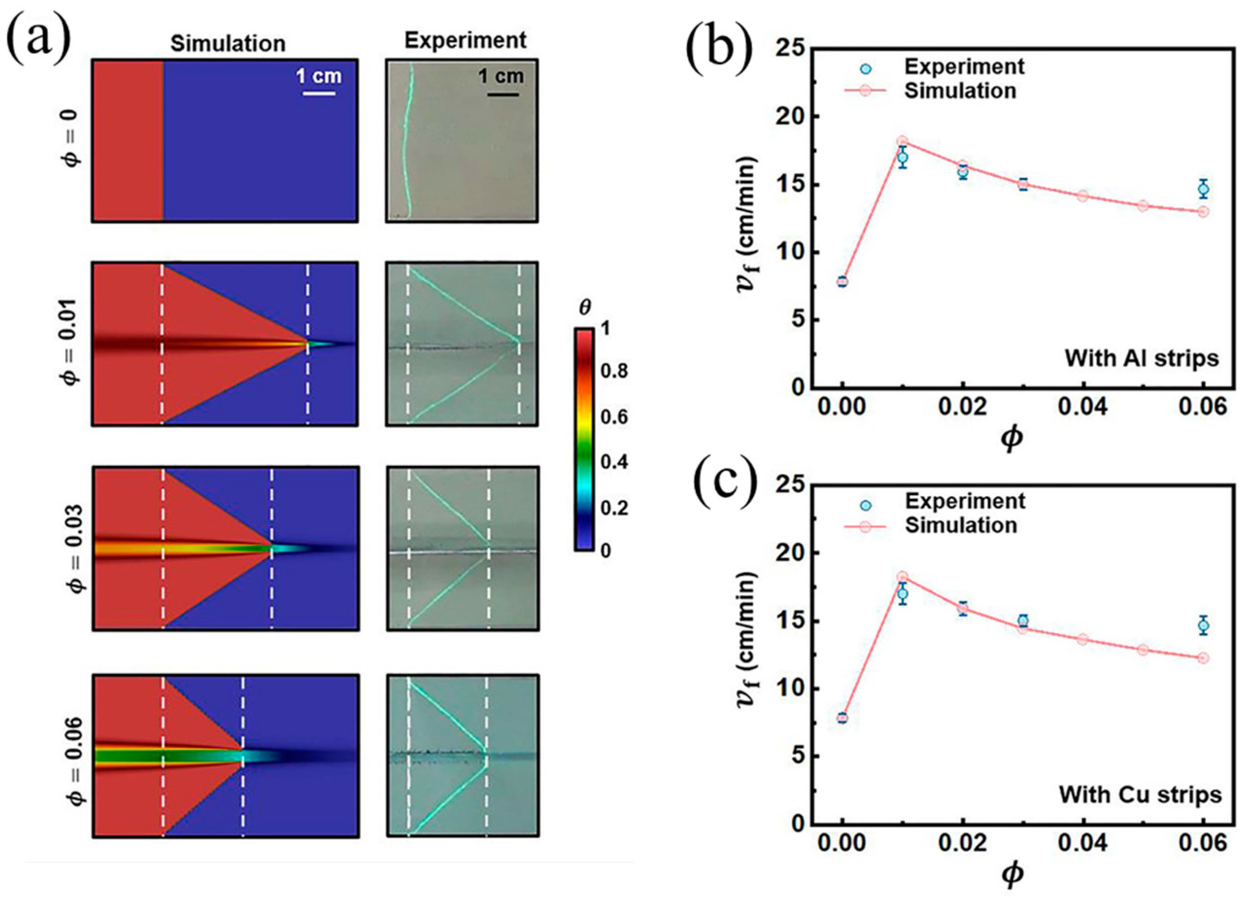
| TMPTA | Luperox 231 (1.5 phr) | - | Polyglass (65 phr) Silica (5 phr) | 7.88 | - | - | [97] |
| TMPTA | Luperox 231 (1.5 phr) | - | Polyglass (65 phr) Silica (5 phr) Al strip (6 vol%) | 14.77 | - | - | [97] |
| TMPTA | Luperox 231 (1.5 phr) | - | Polyglass (65 phr) Silica (5 phr) Cu strip (6 vol%) | 14.65 | - | - | [97] |
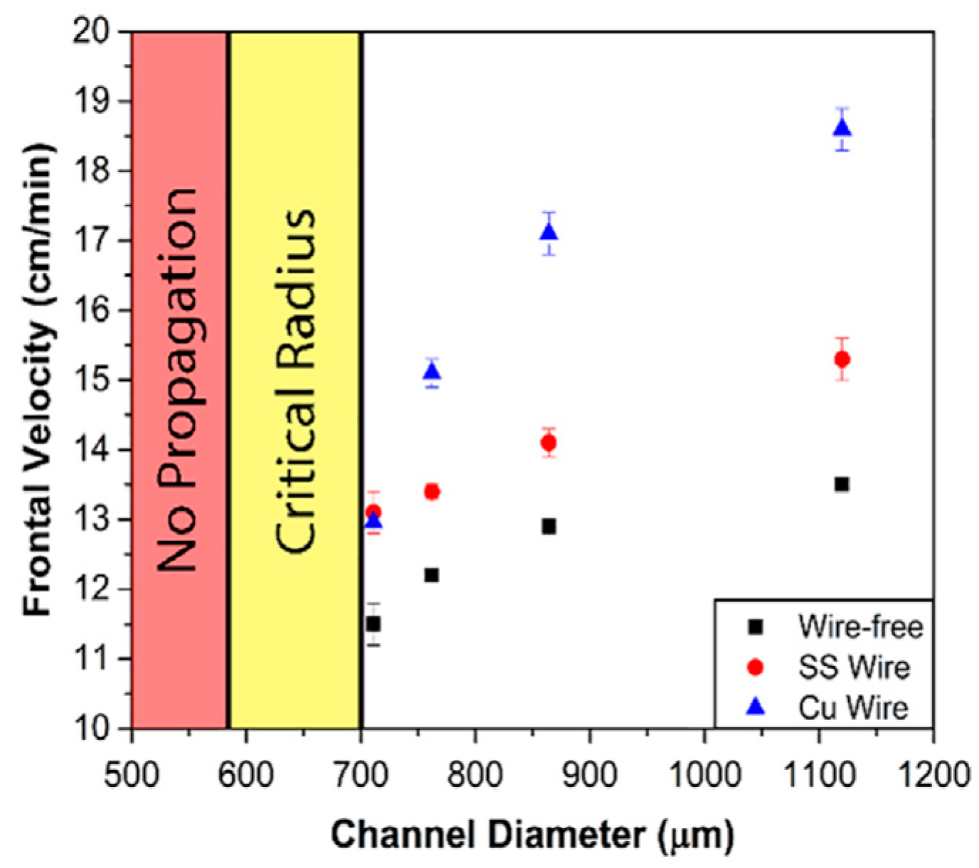
| TMPTA | TETDPPS (0.4 mol%) | - | 12.92 | - | - | [98] | |
| TMPTA | TETDPPS (0.4 mol%) | Stainless steel | 14.06 | - | - | [98] | |
| TMPTA | TETDPPS (0.4 mol%) | Cu | 17.08 | - | - | [98] | |
Disclaimer/Publisher’s Note: The statements, opinions and data contained in all publications are solely those of the individual author(s) and contributor(s) and not of MDPI and/or the editor(s). MDPI and/or the editor(s) disclaim responsibility for any injury to people or property resulting from any ideas, methods, instructions or products referred to in the content. |
© 2024 by the authors. Licensee MDPI, Basel, Switzerland. This article is an open access article distributed under the terms and conditions of the Creative Commons Attribution (CC BY) license (https://creativecommons.org/licenses/by/4.0/).
Share and Cite
Luo, T.; Ma, Y.; Cui, X. Review on Frontal Polymerization Behavior for Thermosetting Resins: Materials, Modeling and Application. Polymers 2024, 16, 185. https://doi.org/10.3390/polym16020185
Luo T, Ma Y, Cui X. Review on Frontal Polymerization Behavior for Thermosetting Resins: Materials, Modeling and Application. Polymers. 2024; 16(2):185. https://doi.org/10.3390/polym16020185
Chicago/Turabian StyleLuo, Tingting, Yating Ma, and Xiaoyu Cui. 2024. "Review on Frontal Polymerization Behavior for Thermosetting Resins: Materials, Modeling and Application" Polymers 16, no. 2: 185. https://doi.org/10.3390/polym16020185
APA StyleLuo, T., Ma, Y., & Cui, X. (2024). Review on Frontal Polymerization Behavior for Thermosetting Resins: Materials, Modeling and Application. Polymers, 16(2), 185. https://doi.org/10.3390/polym16020185