
The Additive Manufacturing Approach to Polydimethylsiloxane (PDMS) Microfluidic Devices: Review and Future Directions


 , , , and
Abstract
1. Introduction
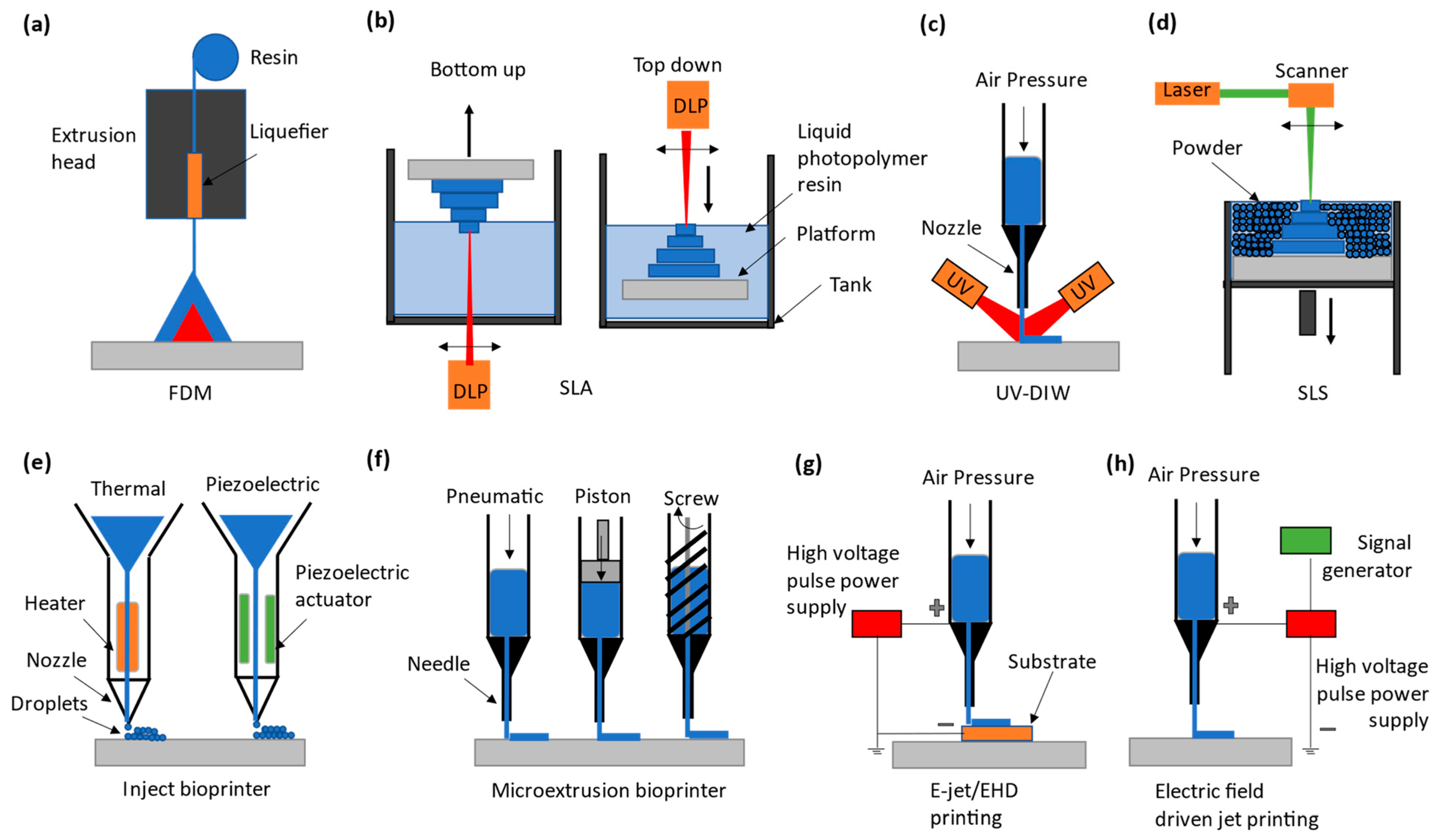
2. The AM Process along with Its Classification
3. Printing of PDMS Microfluidic Devices
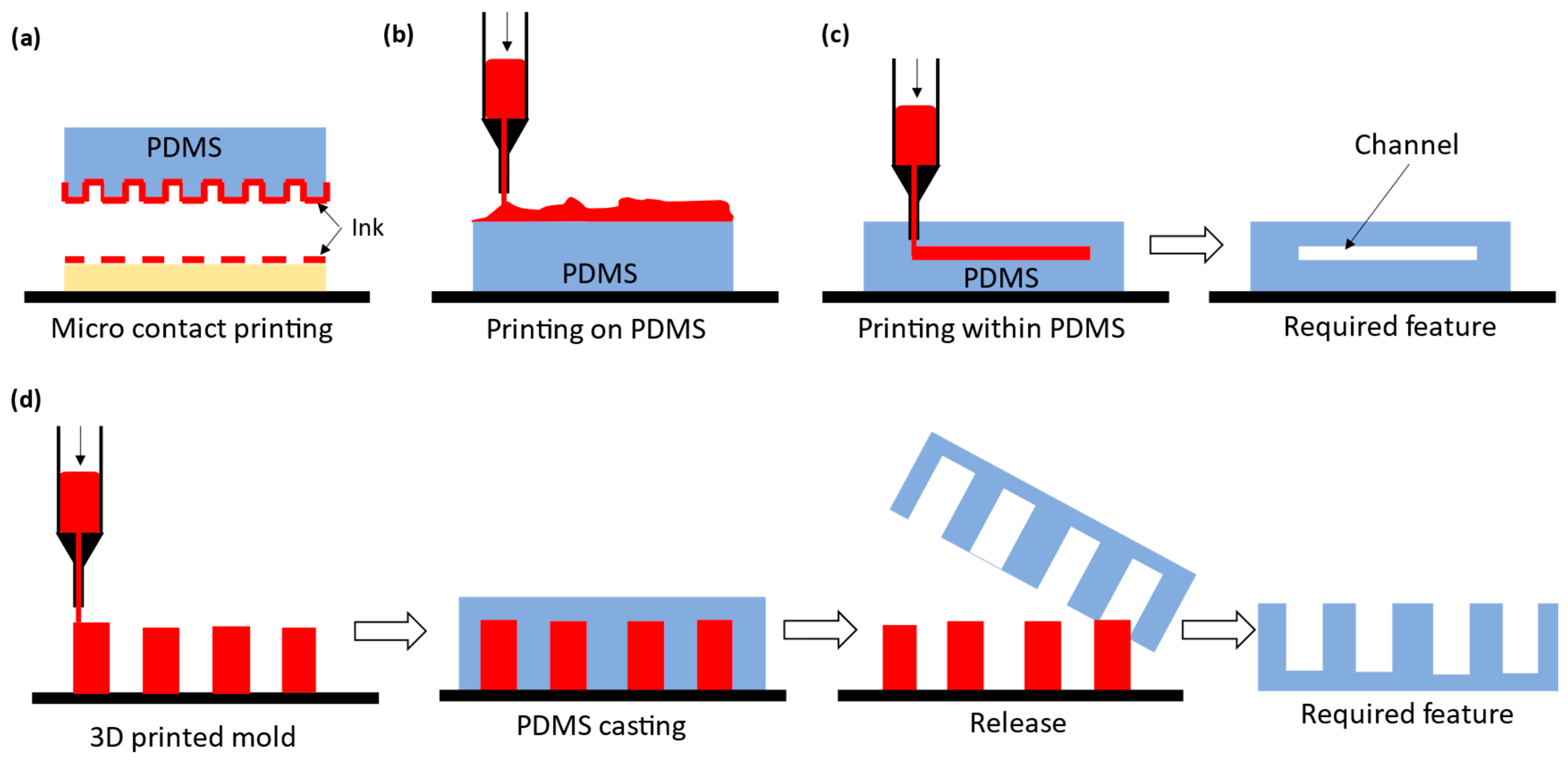
3.1. Indirect PDMS Printing: Micro Contact Printing
3.2. Indirect PDMS Printing: Printing of Materials on PDMS
3.3. Indirect Printing: Printing within PDMS
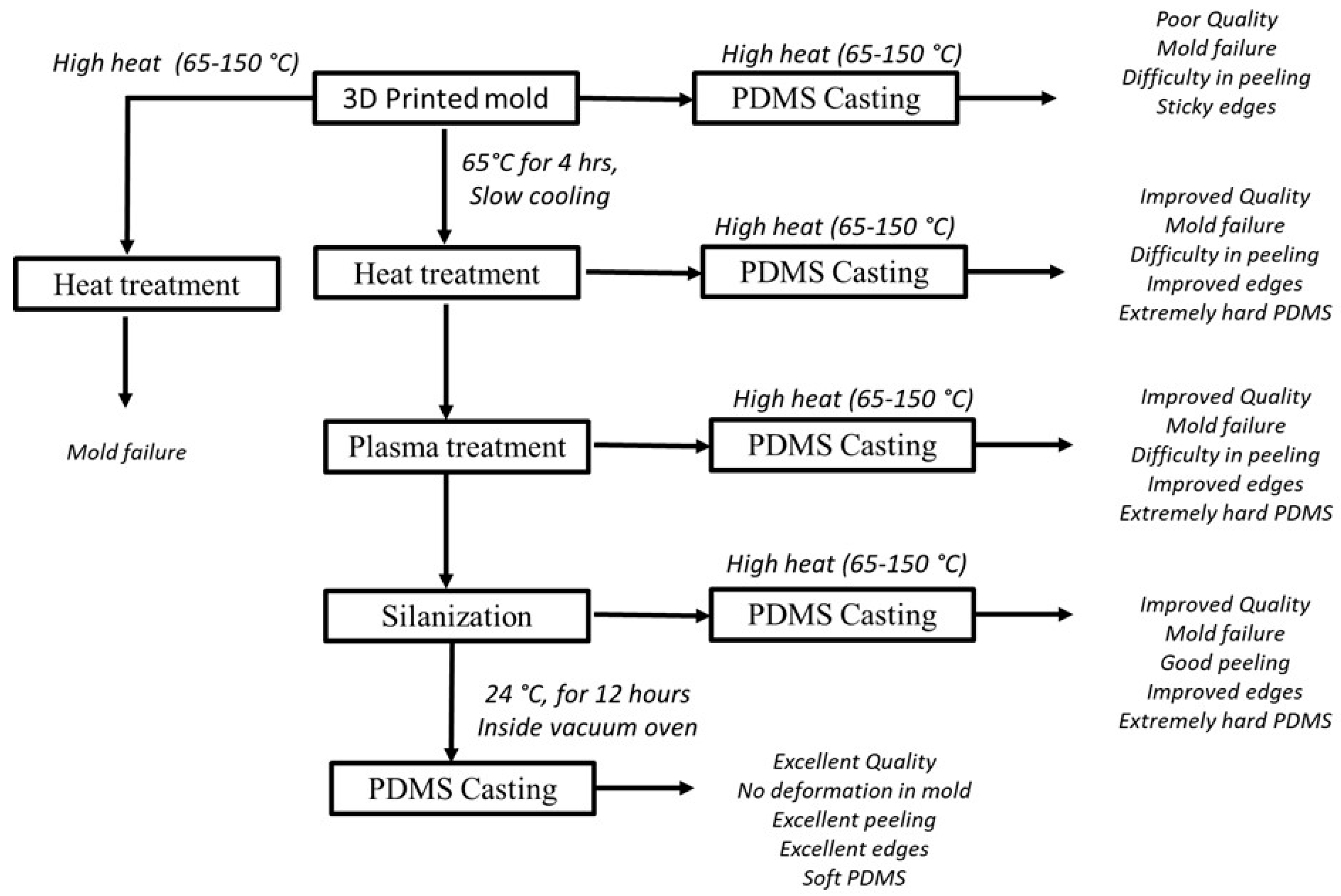
3.4. Indirect PDMS Printing: Printed Mold PDMS
3.5. Direct Printing of PDMS
4. Conclusions, Future Research Directions, and Contributions
Author Contributions
Funding
Institutional Review Board Statement
Data Availability Statement
Acknowledgments
Conflicts of Interest
References
- Lei, L.; Bergstrom, D.; Zhang, B.; Zhang, H.; Yin, R.; Song, K.-Y.; Zhang, W. Micro/Nanospheres Generation by Fluid-Fluid Interaction Technology: A Literature Review. Recent Pat. Nanotechnol. 2017, 11, 15–33. [Google Scholar] [CrossRef] [PubMed]
- Lei, L.; Zhang, H.; Bergstrom, D.J.; Anthony, T.; Song, K.Y.; Zhang, W. Experimental and simulation study of flow patterns in the combined flow focusing and T-junction device. J. Micromech. Microeng. 2020, 30, 055001. [Google Scholar] [CrossRef]
- Tony, A.; Rasouli, A.; Farahinia, A.; Wells, G.; Zhang, H.; Achenbach, S.; Yang, S.M.; Sun, W.; Zhang, W. Toward a Soft Microfluidic System: Concept and Preliminary Developments. In Proceedings of the 2021 27th International Conference on Mechatronics and Machine Vision in Practice (M2VIP), Shanghai, China, 26–28 November 2021; pp. 755–759. [Google Scholar] [CrossRef]
- Wu, X.C.; Wu, X.; Zhan, E.; Zhang, W. Bovine Serum Albumin and Gamma-Globulin in the H2s Measurement by Confocal Laser Scanning Microscopy. SSRN Electron. J. 2022. [Google Scholar] [CrossRef]
- Farahinia, A.; Zhang, W.J.; Badea, I. Circulating Tumor Cell Separation of Blood Cells and Sorting in novel Microfluidic approaches: A review. Preprints. Org. 2020, 41, 491. [Google Scholar] [CrossRef]
- Yang, S.M.; Bi, Q.; Zhang, W.J.; Cui, X.; Zhou, Y.; Yuan, C.; Cui, Y. Highly accurate multiprotein detection on a digital ELISA platform. Lab Chip 2022, 22, 3015–3024. [Google Scholar] [CrossRef]
- Yin, R.; Xin, J.; Yang, D.; Gao, Y.; Zhang, H.; Qian, Z.; Zhang, W. High-Linearity Hydrogel-Based Capacitive Sensor Based on Con A– Sugar Affinity and Low-Melting-Point Metal. Polymers 2022, 14, 4302. [Google Scholar] [CrossRef]
- Lamberti, A.; Marasso, S.L.; Cocuzza, M. PDMS membranes with tunable gas permeability for microfluidic applications. RSC Adv. 2014, 4, 61415–61419. [Google Scholar] [CrossRef]
- Comina, G.; Suska, A.; Filippini, D. PDMS lab-on-a-chip fabrication using 3D printed templates. Lab Chip 2014, 14, 424–430. [Google Scholar] [CrossRef]
- Fujii, T. PDMS-based microfluidic devices for biomedical applications. Microelectron. Eng. 2002, 61, 907–914. [Google Scholar] [CrossRef]
- Campbell, S.B.; Wu, Q.; Yazbeck, J.; Liu, C.; Okhovatian, S.; Radisic, M. Beyond Polydimethylsiloxane: Alternative Materials for Fabrication of Organ-on-a-Chip Devices and Microphysiological Systems. ACS Biomater. Sci. Eng. 2021, 7, 2880–2899. [Google Scholar] [CrossRef]
- Morbioli, G.G.; Speller, N.C.; Stockton, A.M. A practical guide to rapid-prototyping of PDMS-based microfluidic devices: A tutorial. Anal. Chim. Acta 2020, 1135, 150–174. [Google Scholar] [CrossRef]
- Raj M, K.; Chakraborty, S. PDMS microfluidics: A mini review. J. Appl. Polym. Sci. 2020, 137, 48958. [Google Scholar] [CrossRef]
- Torino, S.; Corrado, B.; Iodice, M.; Coppola, G. PDMS-Based Microfluidic Devices for Cell Culture. Inventions 2018, 3, 65. [Google Scholar] [CrossRef]
- Monia Kabandana, G.K.; Zhang, T.; Chen, C. Emerging 3D printing technologies and methodologies for microfluidic development. Anal. Methods 2022, 14, 2885–2906. [Google Scholar] [CrossRef]
- Alkhalaf, Q.; Pande, S.; Palkar, R.R. Review of polydimethylsiloxane (pdms) as a material for additive manufacturing. In Innovative Design, Analysis and Development Practices in Aerospace and Automotive Engineering: Proceedings of I-DAD 2020; Springer: Singapore, 2021; pp. 265–275. [Google Scholar]
- Huang, X.; Ge, M.; Wang, H.; Liang, H.; Meng, N.; Zhou, N. Functional modification of polydimethylsiloxane nanocomposite with silver nanoparticles-based montmorillonite for antibacterial applications. Colloids Surf. A Physicochem. Eng. Asp. 2022, 652, 128666. [Google Scholar] [CrossRef]
- Pakdel, E.; Zhao, H.; Wang, J.; Tang, B.; Varley, R.; Wang, X. Superhydrophobic and photocatalytic self-cleaning on cotton fabric using uorine-free ower-like-TiO2/PDMS coatings. arXiv 2021. [Google Scholar] [CrossRef]
- Shillingford, C.; Maccallum, N.; Wong, T.S.; Kim, P.; Aizenberg, J. Fabrics coated with lubricated nanostructures display robust omniphobicity. Nanotechnology 2013, 25, 014019. [Google Scholar] [CrossRef] [PubMed]
- McDonald, J.C.; Duffy, D.C.; Anderson, J.R.; Chiu, D.T.; Wu, H.; Schueller, O.J.A.; Whitesides, G.M. Fabrication of microfluidic systems in poly(dimethylsiloxane). Electrophoresis 2000, 21, 27–40. [Google Scholar] [CrossRef]
- Yuan, C.; Tony, A.; Yin, R.; Wang, K.; Zhang, W. Tactile and Thermal Sensors Built from Carbon-Polymer Nanocomposites-A Critical Review. Sensors 2021, 21, 1234. [Google Scholar] [CrossRef]
- Miranda, I.; Souza, A.; Sousa, P.; Ribeiro, J.; Castanheira, E.M.S.; Lima, R.; Minas, G. Properties and Applications of PDMS for Biomedical Engineering: A Review. J. Funct. Biomater. 2022, 13, 2. [Google Scholar] [CrossRef]
- Wolf, M.P.; Salieb-Beugelaar, G.B.; Hunziker, P. PDMS with designer functionalities—Properties, modifications strategies, and applications. Prog. Polym. Sci. 2018, 83, 97–134. [Google Scholar] [CrossRef]
- Mukhopadhyay, R. When PDMS isn’t the best. Anal. Chem. 2007, 79, 3249–3253. [Google Scholar] [CrossRef] [PubMed]
- Zhang, W.J.; Wang, J.W. Design theory and methodology for enterprise systems. Enterp. Inf. Syst. 2016, 10, 245–248. [Google Scholar] [CrossRef]
- Zhang, W.J.; Wang, J.W.; Lin, Y. Integrated design and operation management for enterprise systems. Enterp. Inf. Syst. 2019, 13, 424–429. [Google Scholar] [CrossRef]
- Sochol, R.D.; Sweet, E.; Glick, C.C.; Wu, S.Y.; Yang, C.; Restaino, M.; Lin, L. 3D printed microfluidics and microelectronics. Microelectron. Eng. 2018, 189, 52–68. [Google Scholar] [CrossRef]
- Dahlberg, T.; Stangner, T.; Zhang, H.; Wiklund, K.; Lundberg, P.; Edman, L.; Andersson, M. 3D printed water-soluble scaffolds for rapid production of PDMS micro-fluidic flow chambers. Sci. Rep. 2018, 8, 3372. [Google Scholar] [CrossRef]
- Pavone, A.; Stano, G.; Percoco, G. One-Shot 3D Printed Soft Device Actuated Using Metal-Filled Channels and Sensed with Embedded Strain Gauge. 3D Print. Addit. Manuf. 2023, 13, 20220263. [Google Scholar] [CrossRef]
- Castiaux, A.D.; Pinger, C.W.; Hayter, E.A.; Bunn, M.E.; Martin, R.S.; Spence, D.M. PolyJet 3D-Printed Enclosed Microfluidic Channels without Photocurable Supports. Anal. Chem. 2019, 91, 6910–6917. [Google Scholar] [CrossRef]
- Zeraatkar, M.; de Tullio, M.D.; Pricci, A.; Pignatelli, F.; Percoco, G. Exploiting limitations of fused deposition modeling to enhance mixing in 3D printed microfluidic devices. Rapid Prototyp. J. 2021, 27, 1850–1859. [Google Scholar] [CrossRef]
- Brittain, S.; Paul, K.; Zhao, X.M.; Whitesides, G. Soft lithography and microfabrication. Phys. World 1998, 11, 31. [Google Scholar] [CrossRef]
- Zahra, A.; de Cesare, G.; Caputo, D.; Nascetti, A. Caputo Augusto Nascetti Augusto Nascetti Formation of Round Channel for Microfluidic Application & Quot. Available online: https://www.researchgate.net/publication/264352974_Formation_of_round_channel_for_microfluidic_ApplicationInternational (accessed on 7 August 2019).
- Hwang, Y.; Candler, R.N. Non-planar PDMS microfluidic channels and actuators: A review. Lab Chip 2017, 17, 3948–3959. [Google Scholar] [CrossRef] [PubMed]
- Hwang, Y.; Paydar, O.H.; Candler, R.N. 3D printed molds for non-planar PDMS microfluidic channels. Sens. Actuators A Phys. 2015, 226, 137–142. [Google Scholar] [CrossRef]
- Kalyan Jagannadh, V.; Mackenzie, M.D.; Pal, P.; Kar, A.K.; Siva Gorthi, S.; Alberts, B.; Bray, D.; Hopkin, K.; Johnson, A.; Lewis, J.; et al. Deconvolution Microscopy,& quot; in & quot; Microscopy Techniques. Adv. Biochem. Eng. 2014, 15, 201–243. [Google Scholar] [CrossRef]
- Slopes to Prevent Trapping of Bubbles in Microfluidic Channels—Tech Briefs. Available online: https://www.techbriefs.com/component/content/article/tb/techbriefs/physical-sciences/8907 (accessed on 6 August 2019).
- Bonyár, A.; Sántha, H.; Varga, M.; Ring, B.; Vitéz, A.; Harsányi, G. Characterization of rapid PDMS casting technique utilizing molding forms fabricated by 3D rapid prototyping technology (RPT). Int. J. Mater. Form. 2014, 7, 189–196. [Google Scholar] [CrossRef]
- Farahinia, A.; Jamaati, J.; Niazmand, H.; Zhang, W. The effect of heterogeneous surface charges on mixing in a combined electroosmotic/pressure-driven micromixer. J. Brazilian Soc. Mech. Sci. Eng. 2021, 43, 497. [Google Scholar] [CrossRef]
- Macdonald, N.P.; Cabot, J.M.; Smejkal, P.; Guijt, R.M.; Paull, B.; Breadmore, M.C. Comparing Microfluidic Performance of Three-Dimensional (3D) Printing Platforms. Anal. Chem. 2017, 89, 3858–3866. [Google Scholar] [CrossRef]
- Calcagnile, P.; Cacciatore, G.; Demitri, C.; Montagna, F.; Corcione, C.E. A Feasibility Study of Processing Polydimethylsiloxane–Sodium Carboxymethylcellulose Composites by a Low-Cost Fused Deposition Modeling 3D Printer. Materials 2018, 11, 1578. [Google Scholar] [CrossRef]
- Stang, M.; Tashman, J.; Shiwarski, D.; Yang, H.; Yao, L.; Feinberg, A. Embedded 3D Printing of Thermally-Cured Thermoset Elastomers and the Interdependence of Rheology and Machine Pathing. Adv. Mater. Technol. 2023, 8, 2200984. [Google Scholar] [CrossRef]
- Bhattacharjee, N.; Parra-Cabrera, C.; Kim, Y.T.; Kuo, A.P.; Folch, A. Desktop-Stereolithography 3D-Printing of a Poly(dimethylsiloxane)-Based Material with Sylgard-184 Properties. Adv. Mater. 2018, 30, 1800001. [Google Scholar] [CrossRef]
- Du, K.; Basuki, J.; Glattauer, V.; Mesnard, C.; Nguyen, A.T.; Alexander, D.L.J.; Hughes, T.C. Digital Light Processing 3D Printing of PDMS-Based Soft and Elastic Materials with Tunable Mechanical Properties. ACS Appl. Polym. Mater. 2021, 3, 3049–3059. [Google Scholar] [CrossRef]
- Fleck, E.; Sunshine, A.; Denatale, E.; Keck, C.; McCann, A.; Potkay, J. Advancing 3d-printed microfluidics: Characterization of a gas-permeable, high-resolution pdms resin for stereolithography. Micromachines 2021, 12, 1266. [Google Scholar] [CrossRef] [PubMed]
- Song, H.; Rodriguez, N.A.; Oakdale, J.S.; Duoss, E.B.; Crawford, R.H.; Seepersad, C.C. Aging of UV curable PDMS developed for large-scale, high viscosity stereolithography. Polym. Degrad. Stab. 2023, 207, 110227. [Google Scholar] [CrossRef]
- Ji, Z.; Jiang, D.; Zhang, X.; Guo, Y.; Wang, X. Facile Photo and Thermal Two-Stage Curing for High-Performance 3D Printing of Poly(Dimethylsiloxane). Macromol. Rapid Commun. 2020, 41, 2000064. [Google Scholar] [CrossRef] [PubMed]
- Sun, S.; Fei, G.; Wang, X.; Xie, M.; Guo, Q.; Fu, D.; Wang, Z.; Wang, H.; Luo, G.; Xia, H. Covalent adaptable networks of polydimethylsiloxane elastomer for selective laser sintering 3D printing. Chem. Eng. J. 2021, 412, 128675. [Google Scholar] [CrossRef]
- Mikkonen, R.; Puistola, P.; Jö Nkkä, I.; Mä, M. Inkjet Printable Polydimethylsiloxane for All-Inkjet-Printed Multilayered Soft Electrical Applications. Cite This ACS Appl. Mater. Interfaces 2020, 12, 11990–11997. [Google Scholar] [CrossRef]
- Tu, N.; Lo, J.C.C.; Lee, S.W.R. Improved Inkjet Printing of Polydimethylsiloxane Droplets. In Proceedings of the 2022 International Conference on Electronics Packaging (ICEP), Hokkaido, Japan, 11–14 May 2022; pp. 241–242. [Google Scholar] [CrossRef]
- Fay, C.D.; Jeiranikhameneh, A.; Sayyar, S.; Talebian, S.; Nagle, A.; Cheng, K.; Fleming, S.; Mukherjee, P.; Wallace, G.G. Development of a customised 3D printer as a potential tool for direct printing of patient-specific facial prosthesis. Int. J. Adv. Manuf. Technol. 2022, 120, 7143–7155. [Google Scholar] [CrossRef]
- Chen, C.; Meng, H.; Guo, T.; Deshpande, S.; Chen, H. Development of Paper Microfluidics with 3D-Printed PDMS Barriers for Flow Control. ACS Appl. Mater. Interfaces 2022, 14, 40286–40296. [Google Scholar] [CrossRef]
- He, Z.; Chen, Y.; Yang, J.; Tang, C.; Lv, J.; Liu, Y.; Mei, J.; Lau, W.M.; Hui, D. Fabrication of Polydimethylsiloxane films with special surface wettability by 3D printing. Compos. Part B Eng. 2017, 129, 58–65. [Google Scholar] [CrossRef]
- Roh, S.; Parekh, D.P.; Bharti, B.; Stoyanov, S.D.; Velev, O.D. 3D Printing by Multiphase Silicone/Water Capillary Inks. Adv. Mater. 2017, 29, 1701554. [Google Scholar] [CrossRef]
- Jiang, L.; Huang, Y.; Zhang, X.; Qin, H. Electrohydrodynamic inkjet printing of Polydimethylsiloxane (PDMS). Procedia Manuf. 2020, 48, 90–94. [Google Scholar] [CrossRef]
- Zhang, H.; Qi, T.; Zhu, X.; Zhou, L.; Li, Z.; Zhang, Y.F.; Yang, W.; Yang, J.; Peng, Z.; Zhang, G.; et al. 3D Printing of a PDMS Cylindrical Microlens Array with 100% Fill-Factor. ACS Appl. Mater. Interfaces 2021, 13, 36295–36306. [Google Scholar] [CrossRef] [PubMed]
- Bernard, A.; Renault, J.P.; Michel, B.; Bosshard, H.R.; Delamarche, E. Microcontact Printing of Proteins. Adv. Mater. 2000, 12, 1067–1070. [Google Scholar] [CrossRef]
- Thiébaud, P.; Lauer, L.; Knoll, W.; Offenhäusser, A. PDMS device for patterned application of microfluids to neuronal cells arranged by microcontact printing. Biosens. Bioelectron. 2002, 17, 87–93. [Google Scholar] [CrossRef] [PubMed]
- Rozkiewicz, D.I.; Jan´czewski, D.; Jan´czewski, J.; Verboom, W.; Ravoo, B.J.; Reinhoudt, D.N. “Click“ Chemistry by Microcontact Printing. Angew. Chem. Int. Ed. 2006, 45, 5292–5296. [Google Scholar] [CrossRef] [PubMed]
- Liu, C.-X.; Choi, J.-W. Patterning conductive PDMS nanocomposite in an elastomer using microcontact printing. J. Micromech. Microeng. 2009, 19, 085019. [Google Scholar] [CrossRef]
- Mohapatra, A.; Singh, A.; Abbas, S.A.; Lu, Y.-J.; Boopathi, K.M.; Hanmandlu, C.; Kaisar, N.; Lee, C.-H.; Chu, C.-W. Bilayer polymer solar cells prepared with transfer printing of active layers from controlled swelling/de-swelling of PDMS. Nano Energy 2019, 63, 103826. [Google Scholar] [CrossRef]
- Sun, J.; Jiang, J.; Bao, B.; Wang, S.; He, M.; Zhang, X.; Song, Y. Fabrication of Bendable Circuits on a Polydimethylsiloxane (PDMS) Surface by Inkjet Printing Semi-Wrapped Structures. Materials 2016, 9, 253. [Google Scholar] [CrossRef]
- Wu, J.; Roberts, R.C.; Tien, N.C.; Li, D. Inkjet printed silver patterning on PDMS to fabricate microelectrodes for microfluidic sensing. In Proceedings of the IEEE SENSORS 2014, Valencia, Spain, 2–5 November 2014; pp. 1100–1103. [Google Scholar]
- Adly, N.; Weidlich, S.; Seyock, S.; Brings, F.; Yakushenko, A.; Offenhäusser, A.; Wolfrum, B. Printed microelectrode arrays on soft materials: From PDMS to hydrogels. npj Flex. Electron. 2018, 2, 15. [Google Scholar] [CrossRef]
- Abu-Khalaf, J.M.; Al-Ghussain, L.; Al-Halhouli, A. Fabrication of Stretchable Circuits on Polydimethylsiloxane (PDMS) Pre-Stretched Substrates by Inkjet Printing Silver Nanoparticles. Materials 2018, 11, 2377. [Google Scholar] [CrossRef]
- Huttunen, O.H.; Happonen, T.; Hiitola-Keinänen, J.; Korhonen, P.; Ollila, J.; Hiltunen, J. Roll-To-Roll Screen-Printed Silver Conductors on a Polydimethyl Siloxane Substrate for Stretchable Electronics. Ind. Eng. Chem. Res. 2019, 58, 19909–19916. [Google Scholar] [CrossRef]
- Zhang, H.; Chiao, M. Anti-fouling Coatings of Poly(dimethylsiloxane) Devices for Biological and Biomedical Applications. J. Med. Biol. Eng. 2015, 35, 143–155. [Google Scholar] [CrossRef] [PubMed]
- Helmer, D.; Voss, S.; Sachsenheimer, K.; Kotz, F.; Rapp, B.E. Suspended liquid subtractive lithography: Printing three dimensional channels directly into uncured polymeric matrices. In Microfluidics, BioMEMS, and Medical Microsystems XVII.; Gray, B.L., Becker, H., Eds.; SPIE: Bellingham, DC, USA, 2019; Volume 10875, p. 7. [Google Scholar]
- Helmer, D.; Voigt, A.; Wagner, S.; Keller, N.; Sachsenheimer, K.; Kotz, F.; Nargang, T.M.; Rapp, B.E. Suspended Liquid Subtractive Lithography: One-step generation of 3D channel geometries in viscous curable polymer matrices. Sci. Rep. 2017, 7, 7387. [Google Scholar] [CrossRef] [PubMed]
- Grosskopf, A.K.; Truby, R.L.; Kim, H.; Perazzo, A.; Lewis, J.A.; Stone, H.A.; Paulson, J.A. Viscoplastic Matrix Materials for Embedded 3D Printing. ACS Appl. Mater. Interfaces 2018, 10, 23353–23361. [Google Scholar] [CrossRef] [PubMed]
- Rocca, M.; Fragasso, A.; Liu, W.; Heinrich, M.A.; Zhang, Y.S. Embedded Multimaterial Extrusion Bioprinting. SLAS Technol. Transl. Life Sci. Innov. 2018, 23, 154–163. [Google Scholar] [CrossRef] [PubMed]
- O’bryan, C.S.; Bhattacharjee, T.; Hart, S.; Kabb, C.P.; Schulze, K.D.; Chilakala, I.; Sumerlin, B.S.; Sawyer, W.G.; Angelini, T.E. Self-assembled micro-organogels for 3D printing silicone structures. Sci. Adv. 2017, 3, e1602800. [Google Scholar] [CrossRef]
- Hua, W.; Mitchell, K.; Raymond, L.; Valentin, N.; Coulter, R.; Jin, Y. Embedded 3D Printing of PDMS-Based Microfluidic Chips for Biomedical Applications. J. Manuf. Sci. Eng. 2023, 145, 011002. [Google Scholar] [CrossRef]
- Browne, A.W.; Rust, M.J.; Jung, W.; Lee, S.H.; Ahn, C.H. A rapid prototyping method for polymer microfluidics with fixed aspect ratio and 3D tapered channels. Lab Chip 2009, 9, 2941–2946. [Google Scholar] [CrossRef]
- Saitta, L.; Celano, G.; Cicala, G.; Fragalà, M.E.; Stella, G.; Barcellona, M.; Tosto, C.; Bucolo, M. Projection micro-stereolithography versus master–slave approach to manufacture a micro-optofluidic device for slug flow detection. Int. J. Adv. Manuf. Technol. 2022, 120, 4443–4460. [Google Scholar] [CrossRef]
- Jeon, S.; Hoshiar, A.K.; Kim, K.; Lee, S.; Kim, E.; Lee, S.; Kim, J.Y.; Nelson, B.J.; Cha, H.J.; Yi, B.J.; et al. A Magnetically Controlled Soft Microrobot Steering a Guidewire in a Three-Dimensional Phantom Vascular Network. Soft Robot. 2019, 6, 54–68. [Google Scholar] [CrossRef]
- Cairone, F.; Davi, S.; Stella, G.; Guarino, F.; Recca, G.; Cicala, G.; Bucolo, M. 3D-Printed micro-optofluidic device for chemical fluids and cells detection. Biomed. Microdevices 2020, 22, 37. [Google Scholar] [CrossRef]
- Cairone, F.; Afflitto, F.G.; Stella, G.; Cicala, G.; Ashour, M.; Kersaudy-Kerhoas, M.; Bucolo, M. Micro-Optical Waveguides Realization by Low-Cost Technologies. Micro 2022, 2, 123–136. [Google Scholar] [CrossRef]
- Alterkawi, L.; Migliavacca, M. Parallelism and partitioning in large-scale GAs using spark. In Proceedings of the Genetic and Evolutionary Computation Conference, New York, NY, USA, 13–17 July 2019; pp. 736–744. [Google Scholar] [CrossRef]
- Tony, A.; Badea, I.; Yang, C.; Liu, Y.; Wang, K.; Yang, S.M.; Zhang, W. A Preliminary Experimental Study of Polydimethylsiloxane (PDMS)-To-PDMS Bonding Using Oxygen Plasma Treatment Incorporating Isopropyl Alcohol. Polymers 2023, 15, 1006. [Google Scholar] [CrossRef] [PubMed]
- El Moumen, A.; Tarfaoui, M.; Lafdi, K. Modelling of the temperature and residual stress fields during 3D printing of polymer composites. Int. J. Adv. Manuf. Technol. 2019, 104, 1661–1676. [Google Scholar] [CrossRef]
- Zhao, L.; Jiang, Z.; Zhang, C.; Jiang, Z. Development model and experimental characterization of residual stress of 3D printing PLA parts with porous structure. Appl. Phys. A 2021, 127, 98. [Google Scholar] [CrossRef]
- Szost, B.A.; Terzi, S.; Martina, F.; Boisselier, D.; Prytuliak, A.; Pirling, T.; Hofmann, M.; Jarvis, D.J. A comparative study of additive manufacturing techniques: Residual stress and microstructural analysis of CLAD and WAAM printed Ti–6Al–4V components. Mater. Des. 2016, 89, 559–567. [Google Scholar] [CrossRef]
- Jia, D.; Li, F.; Zhang, Y. 3D-printing process design of lattice compressor impeller based on residual stress and deformation. Sci. Rep. 2020, 10, 600. [Google Scholar] [CrossRef]
- Anant Pidge, P.; Kumar, H. Additive manufacturing: A review on 3 D printing of metals and study of residual stress, buckling load capacity of strut members. Mater. Today Proc. 2020, 21, 1689–1694. [Google Scholar] [CrossRef]
- Acevedo, R.; Sedlak, P.; Kolman, R.; Fredel, M. Residual stress analysis of additive manufacturing of metallic parts using ultrasonic waves: State of the art review. J. Mater. Res. Technol. 2020, 9, 9457–9477. [Google Scholar] [CrossRef]
- Jayanth, N.; Jaswanthraj, K.; Sandeep, S.; Mallaya, N.H.; Siddharth, S.R. Effect of heat treatment on mechanical properties of 3D printed PLA. J. Mech. Behav. Biomed. Mater. 2021, 123, 104764. [Google Scholar] [CrossRef]
- Chalgham, A.; Ehrmann, A.; Wickenkamp, I. Mechanical Properties of FDM Printed PLA Parts before and after Thermal Treatment. Polymers 2021, 13, 1239. [Google Scholar] [CrossRef]
- Behzadnasab, M.; Yousefi, A.A.; Ebrahimibagha, D.; Nasiri, F. Effects of processing conditions on mechanical properties of PLA printed parts. Rapid Prototyp. J. 2020, 26, 381–389. [Google Scholar] [CrossRef]
- Karalekas, D.; Aggelopoulos, A. Study of shrinkage strains in a stereolithography cured acrylic photopolymer resin. J. Mater. Process. Technol. 2003, 136, 146–150. [Google Scholar] [CrossRef]
- Weisgrab, G.; Ovsianikov, A.; Costa, P.F. Functional 3D Printing for Microfluidic Chips. Adv. Mater. Technol. 2019, 4, 1900275. [Google Scholar] [CrossRef]
- Koo, N.; Bender, M.; Plachetka, U.; Fuchs, A.; Wahlbrink, T.; Bolten, J.; Kurz, H. Improved mold fabrication for the definition of high quality nanopatterns by Soft UV-Nanoimprint lithography using diluted PDMS material. Microelectron. Eng. 2007, 84, 904–908. [Google Scholar] [CrossRef]
- Koo, N.; Plachetka, U.; Otto, M.; Bolten, J.; Jeong, J.H.; Lee, E.S.; Kurz, H. The fabrication of a flexible mold for high resolution soft ultraviolet nanoimprintlithography. Nanotechnology 2008, 19, 225304. [Google Scholar] [CrossRef] [PubMed]
- Con, C.; Cui, B. Effect of mold treatment by solvent on PDMS molding into nanoholes. Nanoscale Res. Lett. 2013, 8, 394. [Google Scholar] [CrossRef]
- Costa, P.F.; Albers, H.J.; Linssen, J.E.A.; Middelkamp, H.H.T.; Van Der Hout, L.; Passier, R.; Van Den Berg, A.; Malda, J.; Van Der Meer, A.D. Mimicking arterial thrombosis in a 3D-printed microfluidic in vitro vascular model based on computed tomography angiography data. Lab Chip 2017, 17, 2785–2792. [Google Scholar] [CrossRef]
- Razavi Bazaz, S.; Kashaninejad, N.; Azadi, S.; Patel, K.; Asadnia, M.; Jin, D.; Ebrahimi Warkiani, M. Rapid Softlithography Using 3D-Printed Molds. Adv. Mater. Technol. 2019, 4, 1900425. [Google Scholar] [CrossRef]
- Drastíková, E.; Konderlová, K.; Šebestová, A.; Baron, D.; Švecová, P.; Táborská, P.; Vítková, K.; Pospíšilová, V.; Forostyak, S.; Kořístek, Z.; et al. Determination of total protein content in biomedical products by the PDMS-assisted lab-in-a-syringe assay using 3D printed scaffolds removal. J. Anal. Sci. Technol. 2021, 12, 56. [Google Scholar] [CrossRef]
- Venzac, B.; Deng, S.; Mahmoud, Z.; Lenferink, A.; Costa, A.; Bray, F.; Otto, C.; Rolando, C.; Le Gac, S. PDMS Curing Inhibition on 3D-Printed Molds: Why? Also, How to Avoid It? Anal. Chem. 2021, 93, 7180–7187. [Google Scholar] [CrossRef]
- Dinh, T.; Phan, H.P.; Kashaninejad, N.; Nguyen, T.K.; Dao, D.V.; Nguyen, N.T. An On-Chip SiC MEMS Device with Integrated Heating, Sensing, and Microfluidic Cooling Systems. Adv. Mater. Interfaces 2018, 5, 1800764. [Google Scholar] [CrossRef]
- Waheed, S.; Cabot, J.M.; Macdonald, N.P.; Kalsoom, U.; Farajikhah, S.; Innis, P.C.; Nesterenko, P.N.; Lewis, T.W.; Breadmore, M.C.; Paull, B. Enhanced physicochemical properties of polydimethylsiloxane based microfluidic devices and thin films by incorporating synthetic micro-diamond. Sci. Rep. 2017, 7, 15109. [Google Scholar] [CrossRef] [PubMed]
- De Almeida Monteiro Melo Ferraz, M.; Nagashima, J.B.; Venzac, B.; Le Gac, S.; Songsasen, N. 3D printed mold leachates in PDMS microfluidic devices. Sci. Rep. 2020, 10, 994. [Google Scholar] [CrossRef] [PubMed]
- De Almeida Monteiro Melo Ferraz, M.; Nagashima, J.B.; Venzac, B.; Le Gac, S.; Songsasen, N. A dog oviduct-on-a-chip model of serous tubal intraepithelial carcinoma. Sci. Rep. 2020, 10, 1575. [Google Scholar] [CrossRef] [PubMed]
- Jeonghyeon, C.; Seunghyun, K. Fabrication and Demonstration of a 3D-printing/PDMS Integrated Microfluidic Device. Recent Prog. Mater. 2022, 4, 1–12. [Google Scholar] [CrossRef]
- Chen, P.C.; Chou, C.C.; Chiang, C.H. Systematically Studying Dissolution Process of 3D Printed Acrylonitrile Butadiene Styrene (ABS) Mold for Creation of Complex and Fully Transparent Polydimethylsiloxane (PDMS) Fluidic Devices. BioChip J. 2021, 15, 144–151. [Google Scholar] [CrossRef]
- Kang, K.; Oh, S.; Yi, H.; Han, S.; Hwang, Y. Fabrication of truly 3D microfluidic channel using 3D-printed soluble mold. Biomicrofluidics 2018, 12, 014105. [Google Scholar] [CrossRef]
- Chen, P.; Chiang, C.H. Taguchi Method for Investigation of Ultrasonication-Assisted Dissolution of Acrylonitrile Butadiene Styrene (ABS) Rod Enclosed within Polydimethylsiloxane (PDMS) Bulk. IEEE Access 2020, 8, 114910–114915. [Google Scholar] [CrossRef]
- Adams, F.; Qiu, T.; Mark, A.; Fritz, B.; Kramer, L.; Schlager, D.; Wetterauer, U.; Miernik, A.; Fischer, P. Soft 3D-Printed Phantom of the Human Kidney with Collecting System. Ann. Biomed. Eng. 2017, 45, 963–972. [Google Scholar] [CrossRef]
- Chan, H.N.; Chen, Y.; Shu, Y.; Chen, Y.; Tian, Q.; Wu, H. Direct, one-step molding of 3D-printed structures for convenient fabrication of truly 3D PDMS microfluidic chips. Microfluid. Nanofluidics 2015, 19, 9–18. [Google Scholar] [CrossRef]
- Stolovicki, E.; Ziblat, R.; Weitz, D.A. Throughput enhancement of parallel step emulsifier devices by shear-free and efficient nozzle clearance. Lab Chip 2018, 18, 132–138. [Google Scholar] [CrossRef]
- Ozbolat, V.; Dey, M.; Ayan, B.; Povilianskas, A.; Demirel, M.C.; Ozbolat, I.T. 3D Printing of PDMS Improves Its Mechanical and Cell Adhesion Properties. ACS Biomater. Sci. Eng. 2018, 4, 682–693. [Google Scholar] [CrossRef] [PubMed]
- Hinton, T.J.; Hudson, A.; Pusch, K.; Lee, A.; Feinberg, A.W. 3D Printing PDMS Elastomer in a Hydrophilic Support Bath via Freeform Reversible Embedding. ACS Biomater. Sci. Eng. 2016, 2, 1781–1786. [Google Scholar] [CrossRef] [PubMed]
- Bruzewicz, D.A.; Reches, M.; Whitesides, G.M. Low-cost printing of poly (dimethylsiloxane) barriers to define microchannels in paper. Anal. Chem. 2008, 80, 3387–3392. [Google Scholar] [CrossRef] [PubMed]
- Femmer, T.; Kuehne, A.J.C.; Wessling, M. Print your own membrane: Direct rapid prototyping of polydimethylsiloxane. Lab Chip 2014, 14, 2610–2613. [Google Scholar] [CrossRef]
- Sturgess, C.; Tuck, C.J.; Ashcroft, I.A.; Wildman, R.D. 3D reactive inkjet printing of polydimethylsiloxane. J. Mater. Chem. C 2017, 5, 9733–9743. [Google Scholar] [CrossRef]
- Lipton, J.I.; Angle, S.; Lipson, H. 3D Printable Wax-Silicone Actuators. In Proceedings of the.2014 International Solid Freeform Fabrication Symposium, University of Texas at Austin, Austin, TX, USA, 4–6 August 2014. [Google Scholar]
- Bhattacharjee, T.; Zehnder, S.M.; Rowe, K.G.; Jain, S.; Nixon, R.M.; Sawyer, W.G.; Angelini, T.E. Writing in the granular gel medium. Sci. Adv. 2015, 1, e1500655. [Google Scholar] [CrossRef]
- Mannoor, M.S.; Jiang, Z.; James, T.; Kong, Y.L.; Malatesta, K.A.; Soboyejo, W.O.; Verma, N.; Gracias, D.H.; McAlpine, M.C. 3D Printed Bionic Ears. Nano Lett. 2013, 13, 2634–2639. [Google Scholar] [CrossRef]
- Woo, R.; Chen, G.; Zhao, J.; Bae, J. Structure-Mechanical Property Relationships of 3D-Printed Porous Polydimethylsiloxane. ACS Appl. Polym. Mater. 2021, 3, 3496–3503. [Google Scholar] [CrossRef]
- Paoli, R.; Samitier, J. Mimicking the Kidney: A Key Role in Organ-on-Chip Development. Micromachines 2016, 7, 126. [Google Scholar] [CrossRef]
- Gaio, N.; van Meer, B.; Quirós Solano, W.; Bergers, L.; van de Stolpe, A.; Mummery, C.; Sarro, P.; Dekker, R. Cytostretch, an Organ-on-Chip Platform. Micromachines 2016, 7, 120. [Google Scholar] [CrossRef] [PubMed]
- Song, K.-Y.; Zhang, H.; Zhang, W.-J.; Teixeira, A. Enhancement of the surface free energy of PDMS for reversible and leakage-free bonding of PDMS–PS microfluidic cell-culture systems. Microfluid. Nanofluid. 2018, 22, 135. [Google Scholar] [CrossRef]
- Zhu, J.; Wang, M.; Zhang, H.; Yang, S.; Song, K.Y.; Yin, R.; Zhang, W. Effects of Hydrophilicity, Adhesion Work, and Fluid Flow on Biofilm Formation of PDMS in Microfluidic Systems. ACS Appl. Bio Mater. 2020, 3, 8386–8394. [Google Scholar] [CrossRef] [PubMed]
- Mahmood, M.A.; Popescu, A.C. 3D Printing at Micro-Level: Laser-Induced Forward Transfer and Two-Photon Polymerization. Polymers 2021, 13, 2034. [Google Scholar] [CrossRef]
- Castedo, A.; Mendoza, E.; Angurell, I.; Llorca, J. Silicone microreactors for the photocatalytic generation of hydrogen. Catal. Today 2016, 273, 106–111. [Google Scholar] [CrossRef]
- Zhang, W.J.; Ouyang, P.R.; Sun, Z.H. A novel hybridization design principle for intelligent mechatronics systems. In Proceedings of the Abstracts of the International Conference on Advanced Mechatronics: Toward Evolutionary Fusion of IT and Mechatronics: ICAM, Tokyo, Japan, 2010; pp. 67–74. [Google Scholar] [CrossRef]
- Zhang, W.J.; van Luttervelt, C.A. Toward a resilient manufacturing system. CIRP Ann. 2011, 60, 469–472. [Google Scholar] [CrossRef]
- Wang, F.; Qian, Z.; Yan, Z.; Yuan, C.; Zhang, W. A Novel Resilient Robot: Kinematic Analysis and Experimentation. IEEE Access 2020, 8, 2885–2892. [Google Scholar] [CrossRef]
- Men, L.; Wang, K.; Hu, N.; Wang, F.; Deng, Y.; Zhang, W.; Yin, R. Biocompatible polymers with tunable mechanical properties and conductive functionality on two-photon 3D printing. RSC Adv. 2023, 13, 8586–8593. [Google Scholar] [CrossRef]
- Zhang, T.; Zhang, W.; Gupta, M.M. An underactuated self-reconfigurable robot and the reconfiguration evolution. Mech. Mach. Theory 2018, 124, 248–258. [Google Scholar] [CrossRef]
- Bi, Z.M.; Lin, Y.; Zhang, W.J. The general architecture of adaptive robotic systems for manufacturing applications. Robot. Comput. Integr. Manuf. 2010, 26, 461–470. [Google Scholar] [CrossRef]
- Stano, G.; Ovy, S.M.A.I.; Percoco, G.; Zhang, R.; Lu, H.; Tadesse, Y. Additive Manufacturing for Bioinspired Structures: Experimental Study to Improve the Multimaterial Adhesion Between Soft and Stiff Materials. 3D Print. Addit. Manuf. 2023. [Google Scholar] [CrossRef]
- Han, D.; Lee, H. Recent advances in multi-material additive manufacturing: Methods and applications. Curr. Opin. Chem. Eng. 2020, 28, 158–166. [Google Scholar] [CrossRef]
- Liu, F.; Li, T.; Jiang, X.; Jia, Z.; Xu, Z.; Wang, L. The effect of material mixing on interfacial stiffness and strength of multi-material additive manufacturing. Addit. Manuf. 2020, 36, 101502. [Google Scholar] [CrossRef]
- Bhattacharjee, N.; Urrios, A.; Kang, S.; Folch, A. The upcoming 3D-printing revolution in microfluidics. Lab Chip 2016, 16, 1720–1742. [Google Scholar] [CrossRef]
- Li, Y.; Li, B. Direct ink writing 3D printing of polydimethylsiloxane-based soft and composite materials: A mini review. Oxf. Open Mater. Sci. 2022, 2, itac008. [Google Scholar] [CrossRef]
- Nielsen, A.V.; Beauchamp, M.J.; Nordin, G.P.; Woolley, A.T. 3D Printed Microfluidics. Annu. Rev. Anal. Chem. (Palo Alto Calif) 2020, 13, 45–65. [Google Scholar] [CrossRef]


| Starting Status of Material | Principle of Sub-Process 1 for F1 | Principle of Sub-Process 2 for F2 | Selected Materials | Name |
|---|---|---|---|---|
| Polymer melt or resin | Melt solidification | Fusion and diffusion | Polycarbonate (PC), acrylonitrile butadiene styrene (ABS), polylactic acid (PLA), polyetherimide (ULTEM), nylon, carbon-filled nylon, acrylonitrile styrene acrylate (ASA) | Fused deposition modeling (FDM), 3D printing (nickname) |
| Solid (sheet) | Laser cutting of sheet | Diffusion | Adhesive-coated paper, plastic, or metal laminates | Laminated object manufacturing (LOM) |
| Laser cutting of sheet | Diffusion and glue | Polyamides (PA), polystyrenes (PS), thermoplastic elastomers (TPE), polyaryletherketones (PAEK). | Selective deposition lamination (SDL) | |
| Mechanical cutting of sheet | Diffusion under ultrasonic pressure | Various aluminum alloys, nickel alloys, brass, and steels, etc. | Ultrasonic additive manufacturing (UAM) | |
| Solid (powder) | Powder glued with binder | Diffusion and gluing | ABS, ASA, PLA, polycaprolactone (PCL), Vero | Binder jetting |
| Thermal diffusion | Thermal diffusion | PCL, PLA, metal | Selective laser sintering (SLS) | |
| Liquid | Photo-resistivity | Photo-resistivity | Thermosetting acrylates and epoxy | Stereolithography (SLA) |
| Photo-resistivity | Photo-resistivity | 405 nm clear resin (Anycubic) | Digital light processing (DLP) | |
| Liquid solidification | Diffusion | Thermosetting resin with adequate viscosity | Direct writing (DW) or direct ink writing (DIW) | |
| Droplet/photo-resistivity | Photo-resistivity | Vero white, rubber, polypropylene | Polyjet | |
| Extrusion/microwave irradiation or heating | Microwave irradiation or heating | Concrete, ceramics, wood, clay, food products, biomaterials, silicon, polyurethane (PU) | Liquid deposition modeling (LDM) | |
| Droplet/extrusion | Thermal diffusion or UV curing | Hydrogels, bio-compatible copolymers, and cell spheroid binders and powders, polymers, and small molecules | Inkjet bioprinter and material extrusion bioprinter | |
| Extrusion | Thermal diffusion or UV curing | Low-viscosity resins, poly(ε-caprolactone) (PCL), silver paste | E-Jet printing and Electric-Field-Driven (EFD) printing |
| Type of Printing | Material of Printing | Treatment | PDMS Curing | Ref. | |||
|---|---|---|---|---|---|---|---|
| 1 | 2 | 3 | 4 | ||||
| SLA | PIC100 | Flashlight polymerization | Ethanol (100%) rinse at 37 °C for 7 h | Overnight at 60 °C | [95] | ||
| Micro-SLA | Proprietary | Sonicated in ethanol for 2 min | Ink (Pentel NN60) airbrushing | 65 °C for 2 h | [9] | ||
| SLA | Ethanol rinse for 1 min, air dry, UV cured for 600 s | 130 °C for 4 h in oven | Oxygen plasma at high for 3 min | Silanization for 30 min | 80 °C for 4 h | [108] | |
| SLA | Ethanol wash, air dry | UV cure | 80 °C for 24 h | 80 °C for 4 h | [99] | ||
| DLP-SLA | BV-003 | 5 min UV | Isopropanol for 6 h | Corona treatment high power and atm pressure for 1 min | Silanization for 3 h | 70 °C for 2 h | [100] |
| FDM | PLA | 12 h at 60 °C | 48 h at room temperature (~25 °C) | [97] | |||
| PolyJet | Baked overnight at 90 °C | [109] | |||||
| Method of Printing | Printing Material | Achievement | Limitation | Application and Reference |
|---|---|---|---|---|
| Custom made microextrusion-based 3D printer (μE-3DP) | PDMS-TA (sil-thix silicone thickener–Barnes) | Demonstrated possibility of printing ear and compression stain evaluated. Needs further investigation | Optical transparency is questionable; printing accuracy not evaluated; biocompatibility not evaluated | Facial prosthesis [51] |
| Liquid dispenser (Pandasky OL-D331) | PDMS diluted in acetone | PDMS barriers printed using a liquid dispenser | Flow barrier in the form of filter paper is required | Microfluidics [52] |
| Drop-on-demand (DOD) piezoelectric inkjet printing | PDMS- decane–toluene ink | Improved satellite effect problem | Toluene is hazardous. Biocompatibility issues | Flexible wearable electronics [50] |
| Extrusion through nozzle (custom 3D printer modified from CNC setup) | PDMS ink (precured PDMS microbeads, uncured PDMS liquid precursor, and water medium) | Can be 3D printed and cured both in air and under water; bio scaffolds on live tissue | Optical transparency is questionable | [54] |
| Electric-field-driven (EFD) microscale 3D printing (EM3DP-2A) | PDMS Insufficient data | PDMS and curing agent passive mixing at the source using microfluidic chip; no need for vacuum defoaming | High voltage: air flow and curing temperature and printing speed are key parameters | Microlens array, [56] |
| Selective laser sintering (SLS) | Dynamic covalent cross-linked PDMS (PDMS CANs) | Properties not evaluated. Printing accuracy not evaluated | Properties and printing accuracy need to be evaluated | Sportswear insole [48] |
| UV LED DLP stereolithography (Asiga Freeform PRO2 printer) | PDMS–thiourea based resins | Noncytotoxic; tunable mechanical properties; plastic deformation, highly recoverable | Optical transparency is questionable | Soft robotics, medical devices [44] |
| DLP–SLA system (Asiga MAX X27 UV printer) | Photoreactive methacrylate–PDMS copolymer of (98.6%) photoinitiator TPO-L (0.8%); photosensitizer ITX (0.4%); photo absorber and Sudan I (0.2%) | 60 μm deep channels and 20 μm thick membranes produced; gas-permeable; transparency issues; lower transmission | Difficult to remove unpolymerized resin from the micron-scale channels due to high viscosity of the resin. Young’s modulus is much larger and elongation at break is much smaller; not suitable for pneumatic pump application | Microfluidics [45] |
| Customized ultraviolet-assisted direct ink writing (UV-DIW) 3D printer | pPDMS+ M-PDMS + TPO-L ink | Excellent mechanical properties; optical transparency close to Sylgard 184 PDMS | 3D printing followed by thermal cross linking. Biocompatibility needs further evaluation. | Microfluidics, flexible electronics [47] |
| Electrohydrodynamic (EHD) inkjet printing | PDMS–toluene (toluene has a lower viscosity and better volatility) | Printing accuracy not evaluated | Toluene is hazardous; biocompatibility issues | Network structure [55] |
| FDM (3DPRN LAB 3D) | PDMS–Na–CMC composite | Both Neat PDMS and PDMS composite filaments are made and printed; well-adherent layers of composite material | Irregular samples; no control of geometry; no satisfying results have been obtained | [41] |
| UV LED DLP INKREDIBLE 3D bioprinter (Cellink, Sweden) | Blends of two PDMS elastomers, SE 1700 and Sylgard 184 | Improved three-fold mechanical properties with regard to casting mold due to decreased porosity of bubble entrapment. | Printing accuracy not evaluated | Cell adhesion studies [110] |
| Extrusion through nozzle (home-made 3D printer) | Blends of two PDMS elastomers, SE 1700 and Sylgard 184 | Super hydrophobicity; porous structure | Extremally dependent on printing speed; optical transparency is questionable; printing accuracy not evaluated | Super hydrophobic porous film [53] |
| FDM (replicator 2 3D printer (MakerBot)) | PDMS ink and carbopol support bath | Carbopol supports curing times up to 72 h | Releasing printed PDMS from the carbopol support is tedious; cross-section morphology needs to be improved. | [111] |
| UV LED DLP stereolithography | 3DP-PDMS resin | Transparent; cytocompatible; gas-permeable; highly elastic | Low Young’s modulus; ~500 μm resolution achievable with unsupported structure | Microfluidics [43] |
| Inkjet printer (Fujifilm Dimatix DMP) | 1. PDMS mixed with isobutyl acetate (IBA) solvent 2. PDMS mixed with octyl acetate (OA) solvent | Final printed and cured PDMS–OA is free of solvent residues and resembles traditional casting; 5 μm thickness in each layer and maximum of 8 layers possible. | Ink cartridge shelf life 2 days; needs to be stored inside refrigerator. Nozzles clog quickly, IBA- non-reliable, and difficulty in reproducible jetting.; IBA- hazardous; OA slower evaporating | Soft electrical applications [49] |
| UV curing (same parameters as SLA) | PDMS-(trimethyl)pentamethylcyclopentadienylplatinum(IV) (Cp*PtMe3) catalyst | Good tensile strength, PDMS formulation exhibits very good aging properties over time. | UV-exposed samples seem yellowed. Under-cured material with UV alone; requires further UV or thermal curing. Finally cured after few weeks | [46] |
Disclaimer/Publisher’s Note: The statements, opinions and data contained in all publications are solely those of the individual author(s) and contributor(s) and not of MDPI and/or the editor(s). MDPI and/or the editor(s) disclaim responsibility for any injury to people or property resulting from any ideas, methods, instructions or products referred to in the content. |
© 2023 by the authors. Licensee MDPI, Basel, Switzerland. This article is an open access article distributed under the terms and conditions of the Creative Commons Attribution (CC BY) license (https://creativecommons.org/licenses/by/4.0/).
Share and Cite
Tony, A.; Badea, I.; Yang, C.; Liu, Y.; Wells, G.; Wang, K.; Yin, R.; Zhang, H.; Zhang, W. The Additive Manufacturing Approach to Polydimethylsiloxane (PDMS) Microfluidic Devices: Review and Future Directions. Polymers 2023, 15, 1926. https://doi.org/10.3390/polym15081926
Tony A, Badea I, Yang C, Liu Y, Wells G, Wang K, Yin R, Zhang H, Zhang W. The Additive Manufacturing Approach to Polydimethylsiloxane (PDMS) Microfluidic Devices: Review and Future Directions. Polymers. 2023; 15(8):1926. https://doi.org/10.3390/polym15081926
Chicago/Turabian StyleTony, Anthony, Ildiko Badea, Chun Yang, Yuyi Liu, Garth Wells, Kemin Wang, Ruixue Yin, Hongbo Zhang, and Wenjun Zhang. 2023. "The Additive Manufacturing Approach to Polydimethylsiloxane (PDMS) Microfluidic Devices: Review and Future Directions" Polymers 15, no. 8: 1926. https://doi.org/10.3390/polym15081926
APA StyleTony, A., Badea, I., Yang, C., Liu, Y., Wells, G., Wang, K., Yin, R., Zhang, H., & Zhang, W. (2023). The Additive Manufacturing Approach to Polydimethylsiloxane (PDMS) Microfluidic Devices: Review and Future Directions. Polymers, 15(8), 1926. https://doi.org/10.3390/polym15081926