
Improving the Integrated Fabrication of Insulation Systems in Electric Drives by Injection Molding of Thermosets Due to Processing Conditions and Slot Design


Abstract
: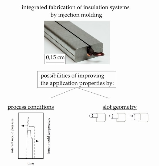
1. Introduction
2. Materials and Methods
2.1. Material
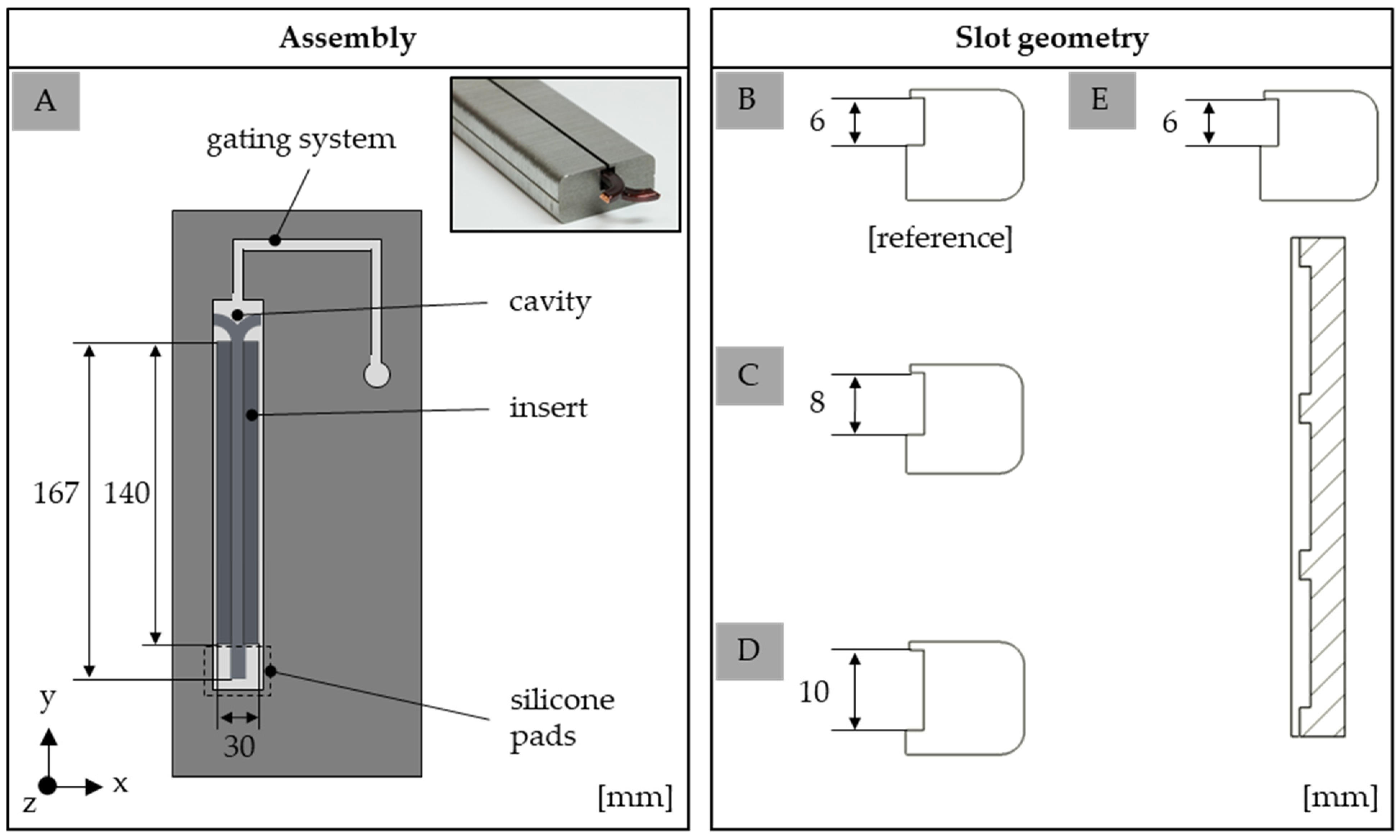
2.2. Fabrication of the Test Specimens
2.3. Characterization
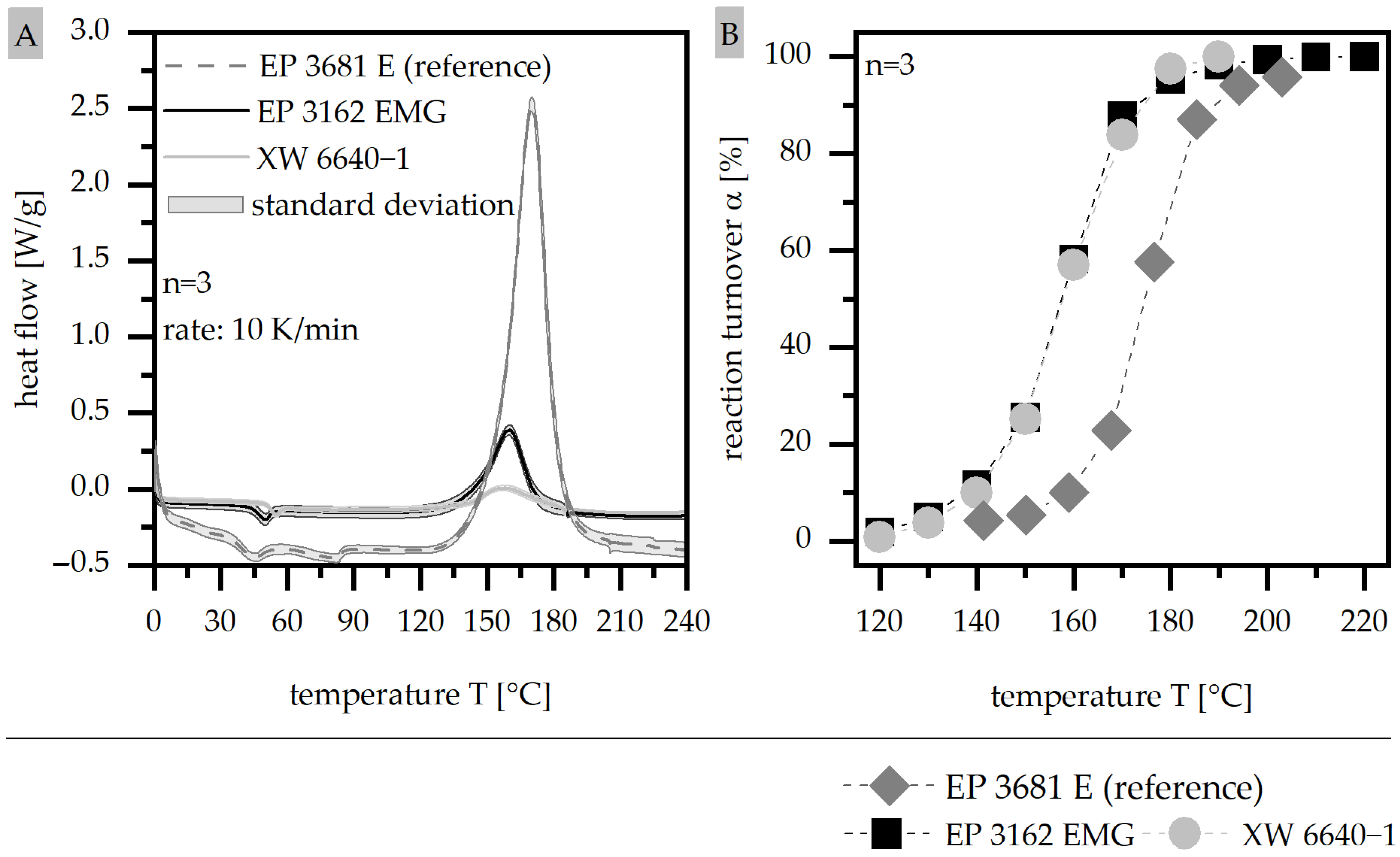
2.3.1. Differential Scanning Calorimetry (DSC) According to ISO 11357
2.3.2. Determination of the Viscosity Using a Rotational Viscometer According to DIN EN 6043
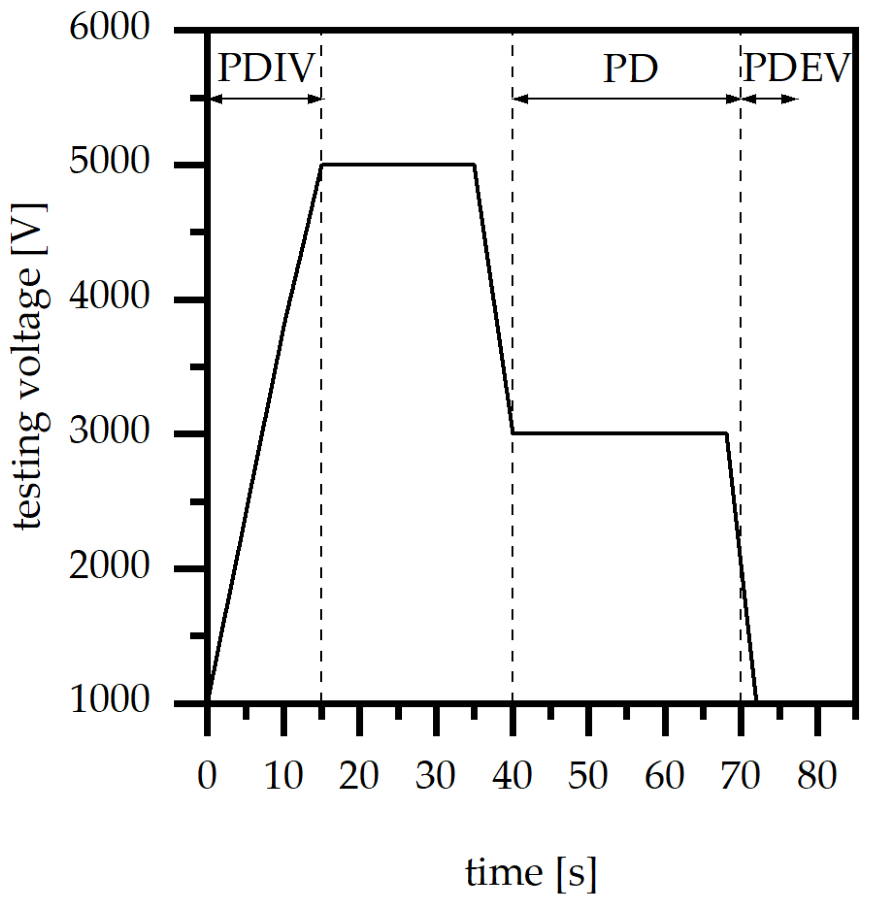
2.3.3. Average of Partial Discharge (PD) and Partial Discharge Extinction Voltage (PDEV)
2.3.4. Microscopy
3. Results
3.1. Differential Scanning Calorimetry (DSC) According to ISO 11357
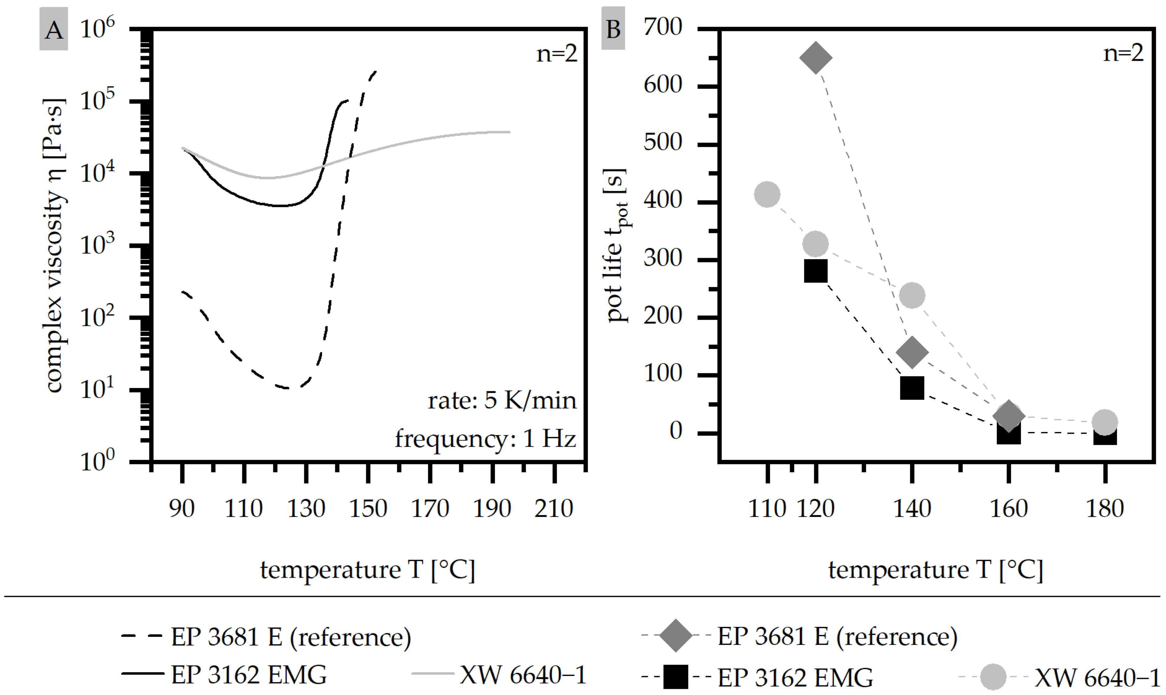
3.2. Determination of the Viscosity Using a Rotational Viscometer According to DIN EN 6043
3.3. Average of Partial Discharge (PD) and Partial Discharge Extinction Voltage (PDEV)
3.3.1. Mold Temperature
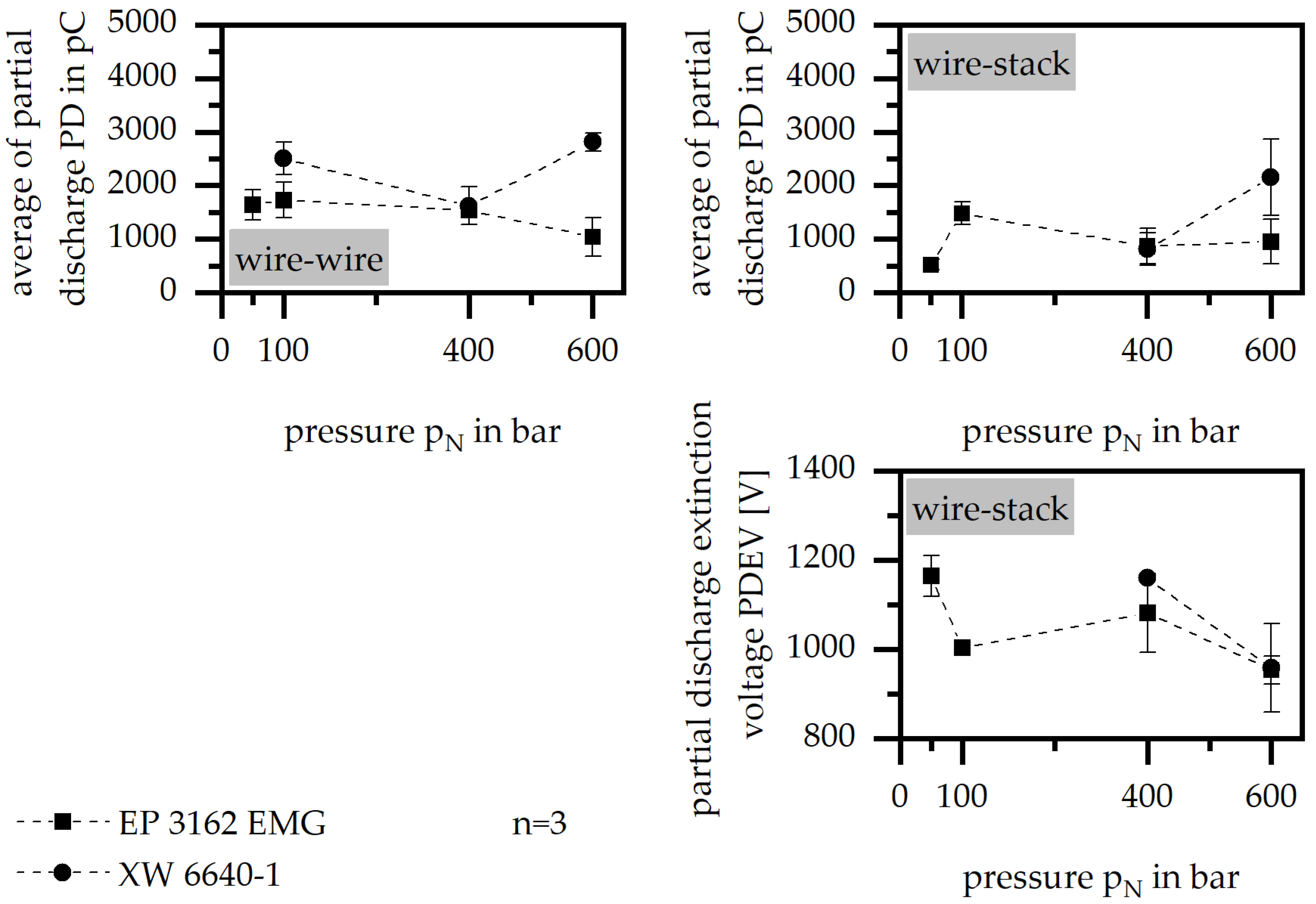
3.3.2. Holding Pressure
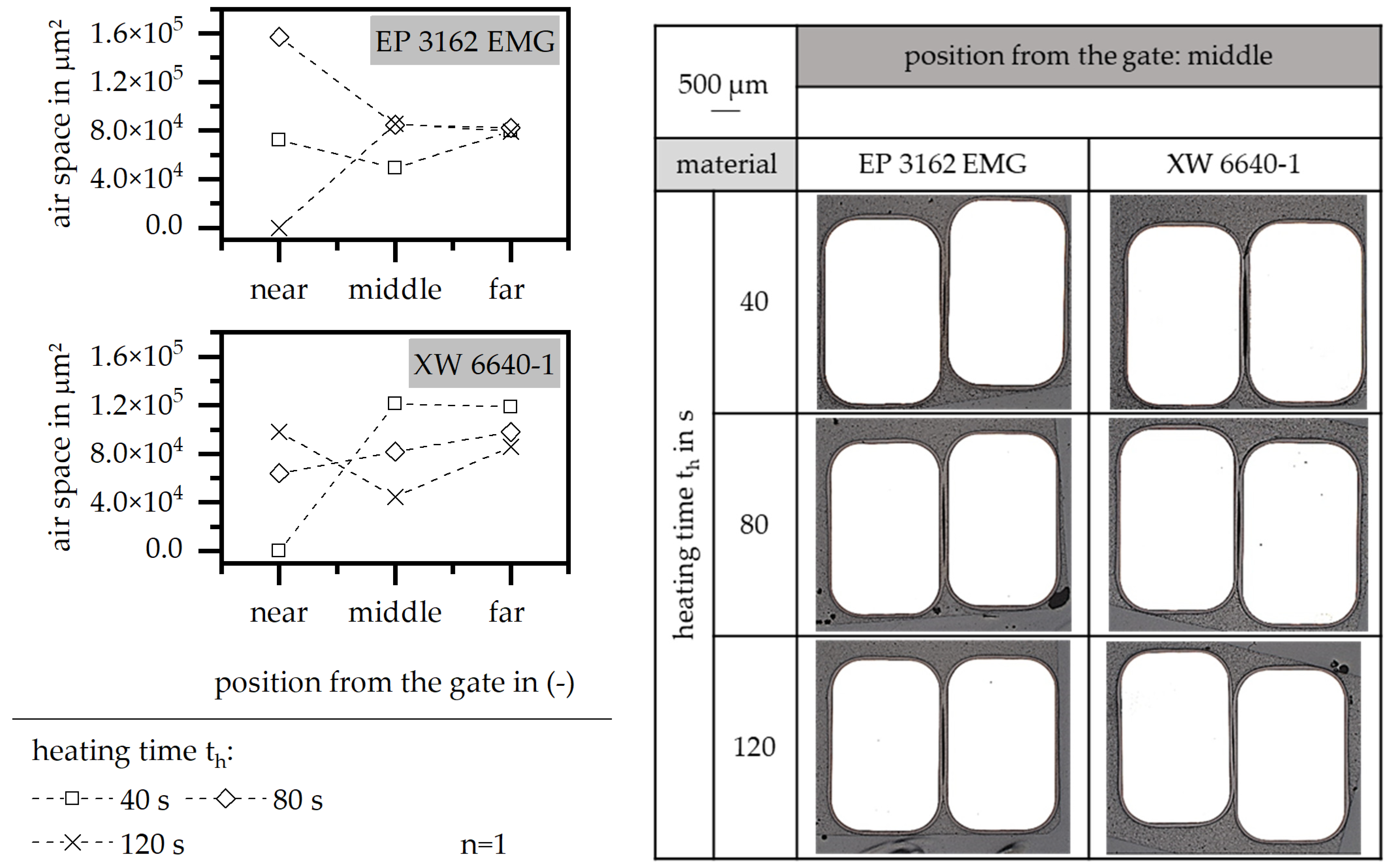
3.3.3. Heating Time
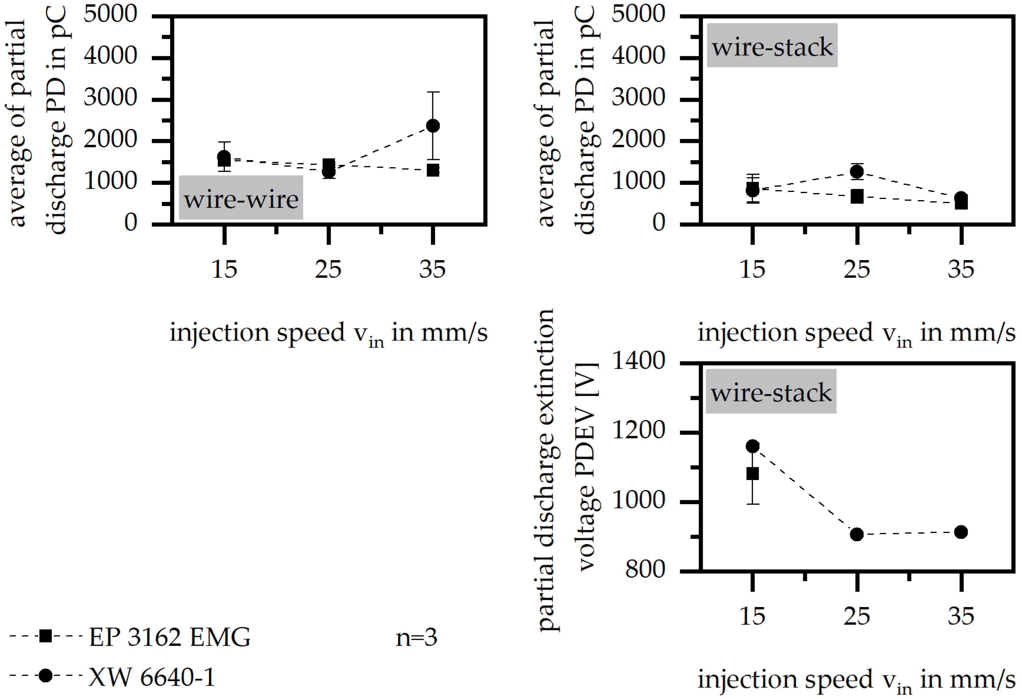
3.3.4. Injection velocity
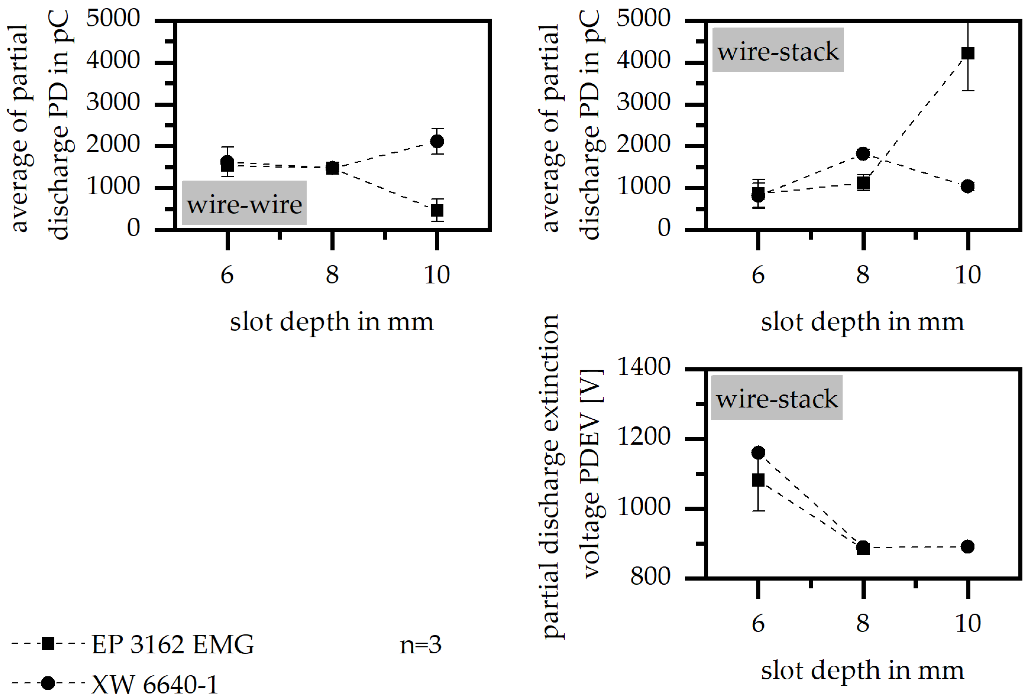
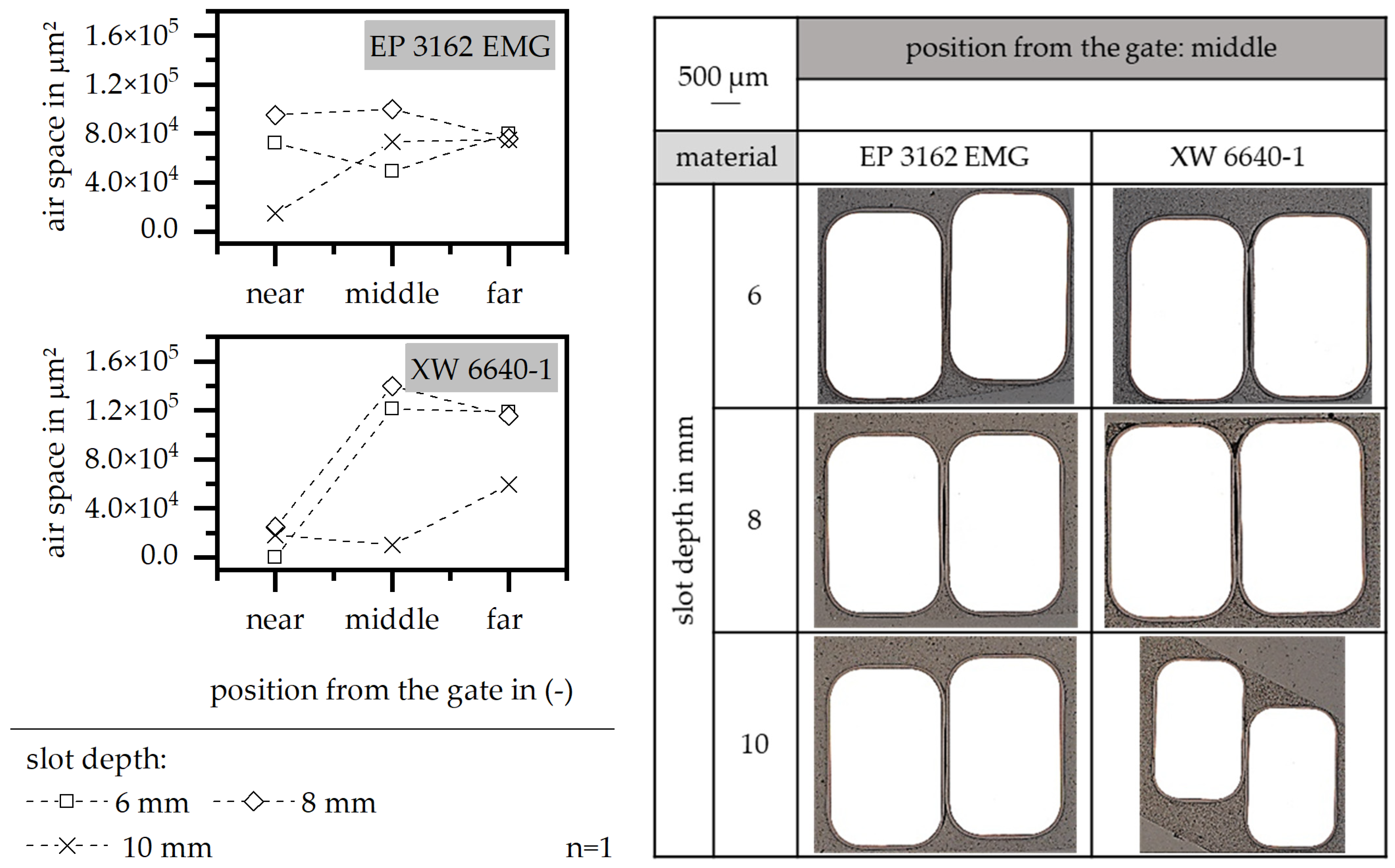
3.3.5. Slot Depth
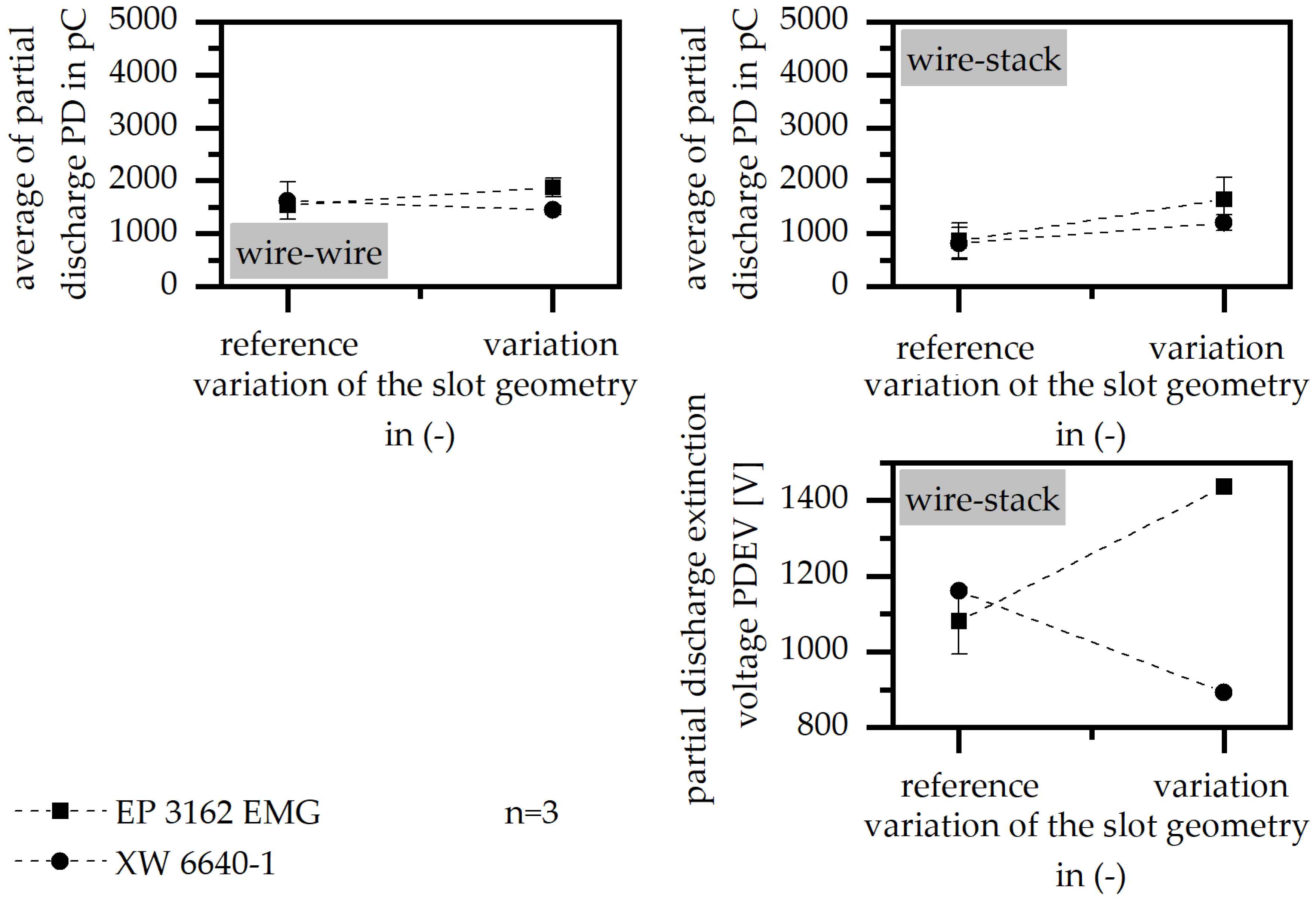
3.3.6. Flow-Improving Grooves
3.4. Microscopy
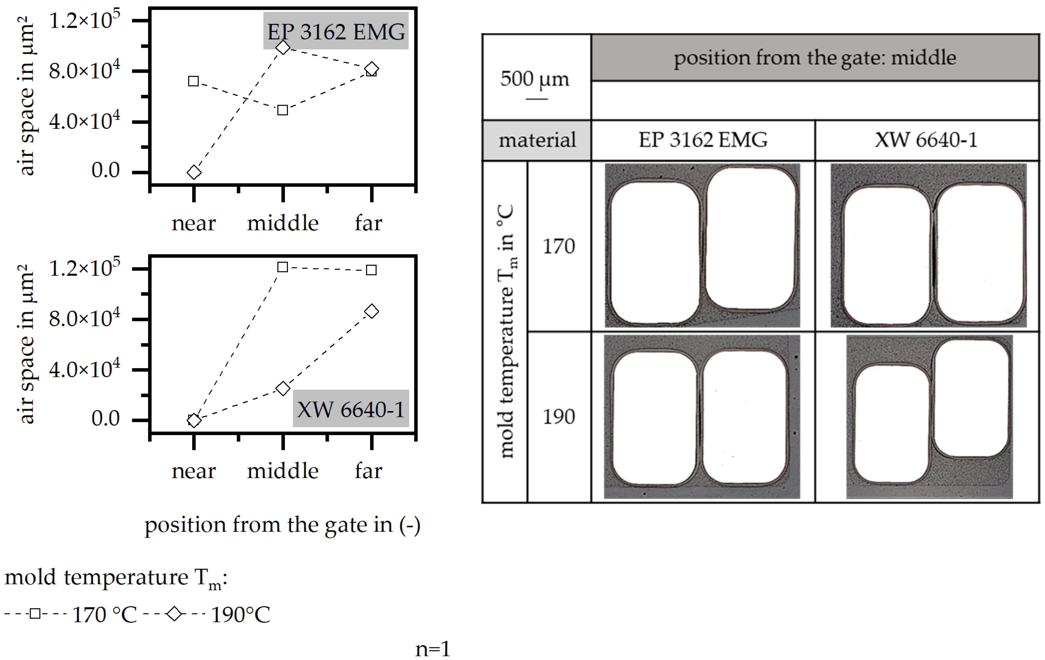
3.4.1. Mold Temperature
3.4.2. Holding Pressure
3.4.3. Heating Time
3.4.4. Injection Velocity
3.4.5. Slot Depth
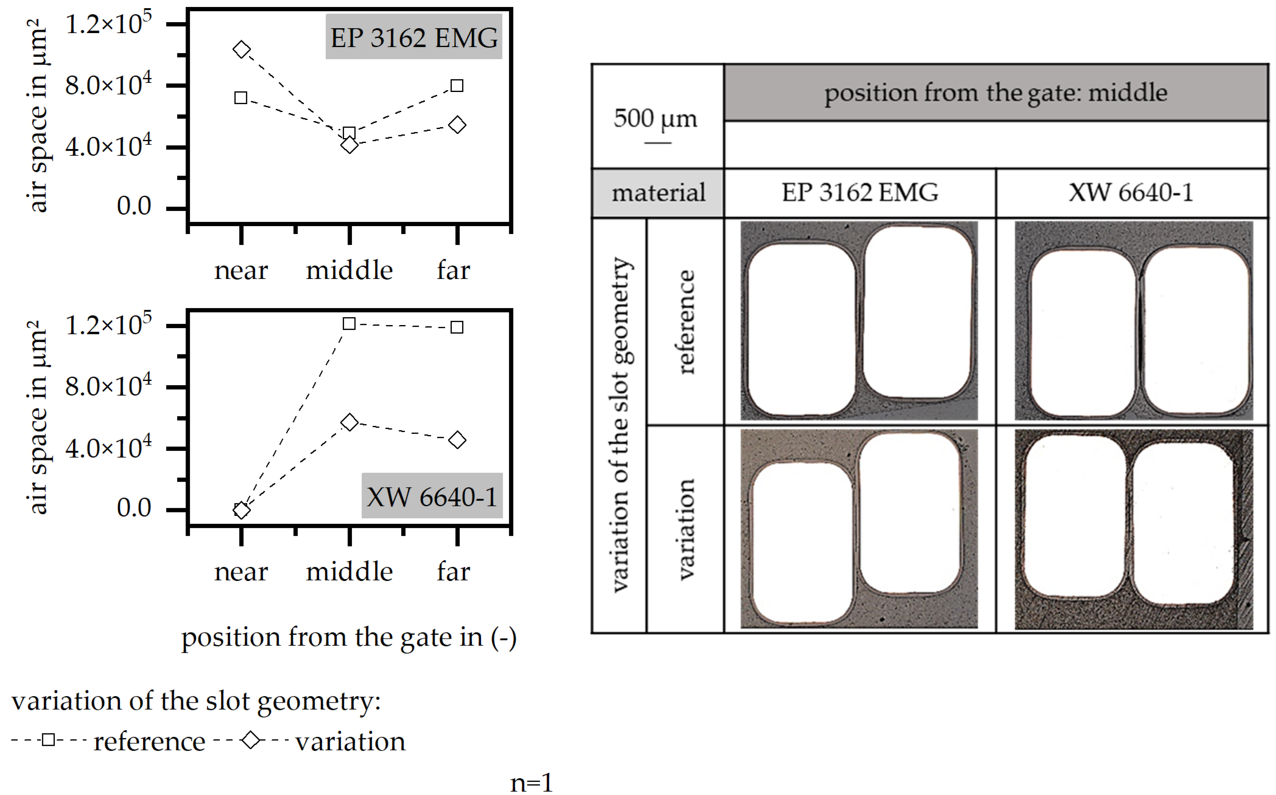
3.4.6. Flow-Improving Grooves
4. Conclusions
Author Contributions
Funding
Data Availability Statement
Acknowledgments
Conflicts of Interest
References
- Gläßel, T.; Franke, J. Kontaktierung von Antrieben für die Elektromobilität. Z. Wirtsch. Fabr. 2017, 112, 322–326. [Google Scholar] [CrossRef]
- Küchler, A. Hochspannungstechnik: Grundlagen—Technologie—Anwendung, 4th ed.; Springer: Berlin/Heidelberg, Germany, 2017. [Google Scholar]
- Riedel, A.; Masuch, M.; Weigelt, T.; Gläßel, T.; Kühl, A.; Reinstein, S.; Franke, J. Challenges of the Hairpin Technology for production Techniques. In Proceedings of the 2028 21st International Conference on Electrical Machnies and Systems (ICEMS), Jeju, Republic of Korea, 7–10 October 2018; pp. 2471–2476. [Google Scholar]
- Tzscheutschler, R.; Olbrisch, H.; Jordan, W. Technologie des Elektromaschinenbaus; Verlag Technik: Berlin, Germany, 1990. [Google Scholar]
- Polymers for Electrical Insulation: Coatings and Casting Materials for the Electrical Industry; Verl. Moderne Industrie: Landsberg, Germany, 2008.
- Riedel, A.; Kneidl, M.; Seefried, J.; Kuehl, A.; Franke, J. Comparison of Various Manufacturing Processes for Hairpin-Stators with Different Conductor Material. In Production at the Leading Edge of Technology; Behrens, B.-A., Brosius, A., Drossel, W.-G., Hintze, W., Ihlenfeldt, S., Nyhuis, P., Eds.; Springer International Publishing: Cham, Switzerland, 2022; pp. 395–402. [Google Scholar]
- Baur, E.; Osswald, T.; Rudolph, N.; Brinkmann, S.; Schmachtenberg, E. Saechtling Kunststoff Taschenbuch, 31st ed.; Carl Hanser Verlag: München, Germany, 2013. [Google Scholar]
- Brahm, M. Polymerchemie Kompakt: Grundlagen—Struktur der Makromoleküle. Technisch Wichtige Polymere und Reaktionssysteme, 2nd ed.; Hirzel: Stuttgart, Germany, 2009. [Google Scholar]
- Woebcken, W. Kunststoff-Handbuch: 10: Duroplast; Hanser: München, Germany, 1988. [Google Scholar]
- Mayer, C. Prozessanalyse und Modellbildung zur Herstellung Gewebeverstärkter, Thermoplastischer Halbzeuge. Ph.D. Dissertation, Technische Universität Kaiserslautern, Kaiserslautern, Germany, 2000. [Google Scholar]
- Arcy, H.D. Exposition et Application des Principes a Suivre des Formules a Emplyer dans les Questions de Distribution d’eau; Dalmont Victor: Paris, France, 1856. [Google Scholar]
- Deringer, T. Integrative manufacturing of thermoset injection molding components with continous fiber-reinforcement. Z. Kunstst. 2019, 1, 169–187. [Google Scholar] [CrossRef]
- Reuter, S.; Sorg, T.; Liebertseder, J.; Dopperbauer, M. Design and Evaluation of a houseless high Performance Machine with thermoset Molded internal Cooling. In Proceedings of the 2021 11th IEEE International Electric Drives Production Conference (EDPC), Erlangen, Germany, 7–9 December 2021. [Google Scholar]
- Szabo, L.; Simon, F.; Lambert, Z.; Szalay, P. Stator Having an Extrusion Coating and Electrical Machine with the Stator. Europäisches Patentamt DE102013227054, 25 June 2015. [Google Scholar]
- Ortloff, P. DEvice for Controlling Direct Current Motor, Has Coil Elements, Which Are Arranged Partially in Star-Connection with Different Windings and Has Neutral Point, Where Windings and Neutral Point Are Connected to a Computer Unit. Europäisches Patentamt DE102007004359A1, 31 July 2008. [Google Scholar]
- Rösel, U.; Kneidl, M.; Drummer, D.; Franke, J. Possibilities of Integrated Fabrication of Insulation Systems in Electric Drives by Injection Molding of Thermosets. Polymers 2022, 14, 5352. [Google Scholar] [CrossRef] [PubMed]
- Raschig GmbH, Technisches Datenblatt: Epoxidur EP 3162 E. 2019. Available online: https://www.raschig.de/downloads/buk/tdb/TDB%20-%20Epoxidur%20EP%203162%20E.pdf (accessed on 24 February 2023).
- Duresco GmbH. Technisches Datenblatt: XW 6640-1. 2022. Available online: https://www.duresco.ch/produkte/datenblaetter/ (accessed on 24 February 2023).


| Process Parameters | Niveau of the Processing Conditions | ||||
|---|---|---|---|---|---|
| -- | - | 0 | + | ++ | |
| mass temperature [°C] | x | x | 85 | x | x |
| mold temperature [°C] | x | x | 170 | 190 | x |
| insert temperature [°C] | x | x | 170 | x | x |
| holding pressure [bar] | 50 | 100 | 400 | 600 | x |
| heating time [s] | x | x | 40 | 80 | 120 |
| injection speed [mm/s] | x | x | 15 | 25 | 35 |
| Improvement of PD and PDEV by | ||
|---|---|---|
| Process parameters | mold temperature | reduction |
| holding pressure | increase | |
| heating time | reduction | |
| injection speed | reduction | |
| Slot geometry | slot depth | increase |
| flow-improving grooves | implementation of the variation |
| Improvement in Full Encapsulation by | ||
|---|---|---|
| Process parameters | mold temperature | increase |
| holding pressure | increase | |
| heating time | reduction | |
| injection speed | reduction/increase (*) | |
| Slot geometry | slot depth | increase |
| Flow-improving grooves | implementation of the variation |
Disclaimer/Publisher’s Note: The statements, opinions and data contained in all publications are solely those of the individual author(s) and contributor(s) and not of MDPI and/or the editor(s). MDPI and/or the editor(s) disclaim responsibility for any injury to people or property resulting from any ideas, methods, instructions or products referred to in the content. |
© 2023 by the authors. Licensee MDPI, Basel, Switzerland. This article is an open access article distributed under the terms and conditions of the Creative Commons Attribution (CC BY) license (https://creativecommons.org/licenses/by/4.0/).
Share and Cite
Rösel, U.; Kneidl, M.; Franke, J.; Drummer, D. Improving the Integrated Fabrication of Insulation Systems in Electric Drives by Injection Molding of Thermosets Due to Processing Conditions and Slot Design. Polymers 2023, 15, 1165. https://doi.org/10.3390/polym15051165
Rösel U, Kneidl M, Franke J, Drummer D. Improving the Integrated Fabrication of Insulation Systems in Electric Drives by Injection Molding of Thermosets Due to Processing Conditions and Slot Design. Polymers. 2023; 15(5):1165. https://doi.org/10.3390/polym15051165
Chicago/Turabian StyleRösel, Uta, Maximilian Kneidl, Jörg Franke, and Dietmar Drummer. 2023. "Improving the Integrated Fabrication of Insulation Systems in Electric Drives by Injection Molding of Thermosets Due to Processing Conditions and Slot Design" Polymers 15, no. 5: 1165. https://doi.org/10.3390/polym15051165
APA StyleRösel, U., Kneidl, M., Franke, J., & Drummer, D. (2023). Improving the Integrated Fabrication of Insulation Systems in Electric Drives by Injection Molding of Thermosets Due to Processing Conditions and Slot Design. Polymers, 15(5), 1165. https://doi.org/10.3390/polym15051165