
Thinning of Poly(methyl methacrylate) and Poly(vinyl chloride) Thin Films Induced by High-Energy Ions of Different Stopping Powers


Abstract
:1. Introduction
2. Materials and Methods
3. Results
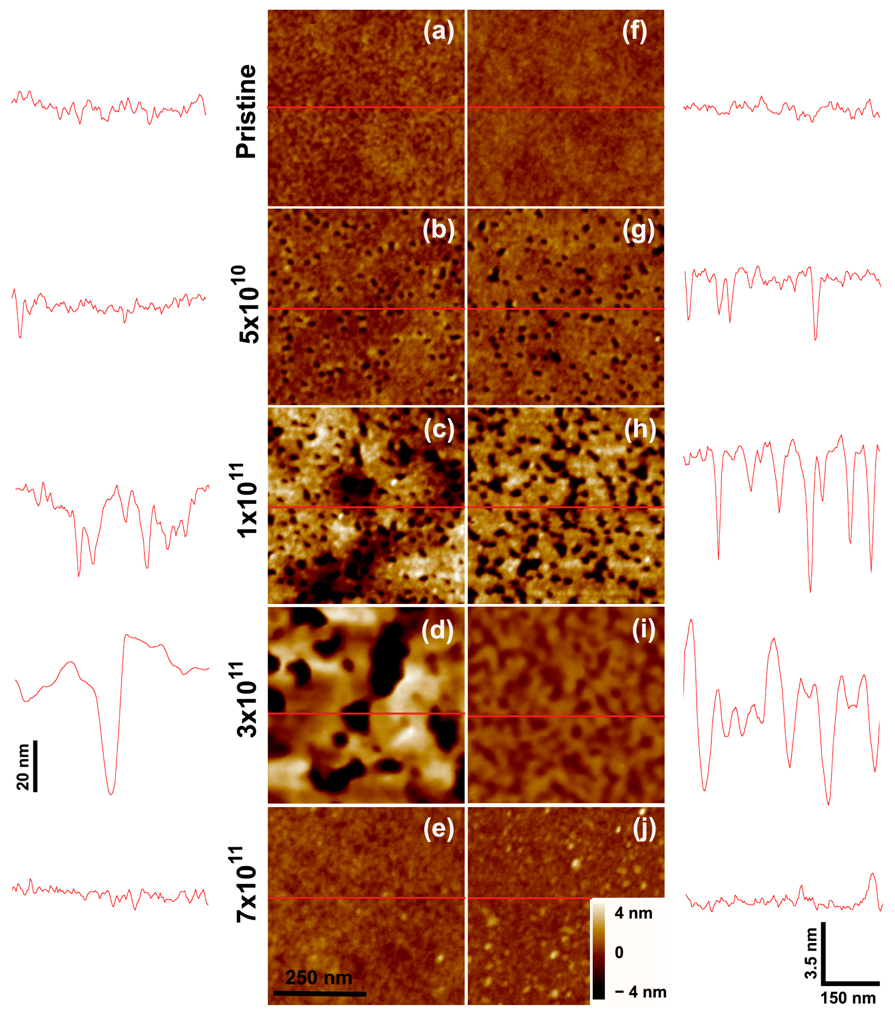
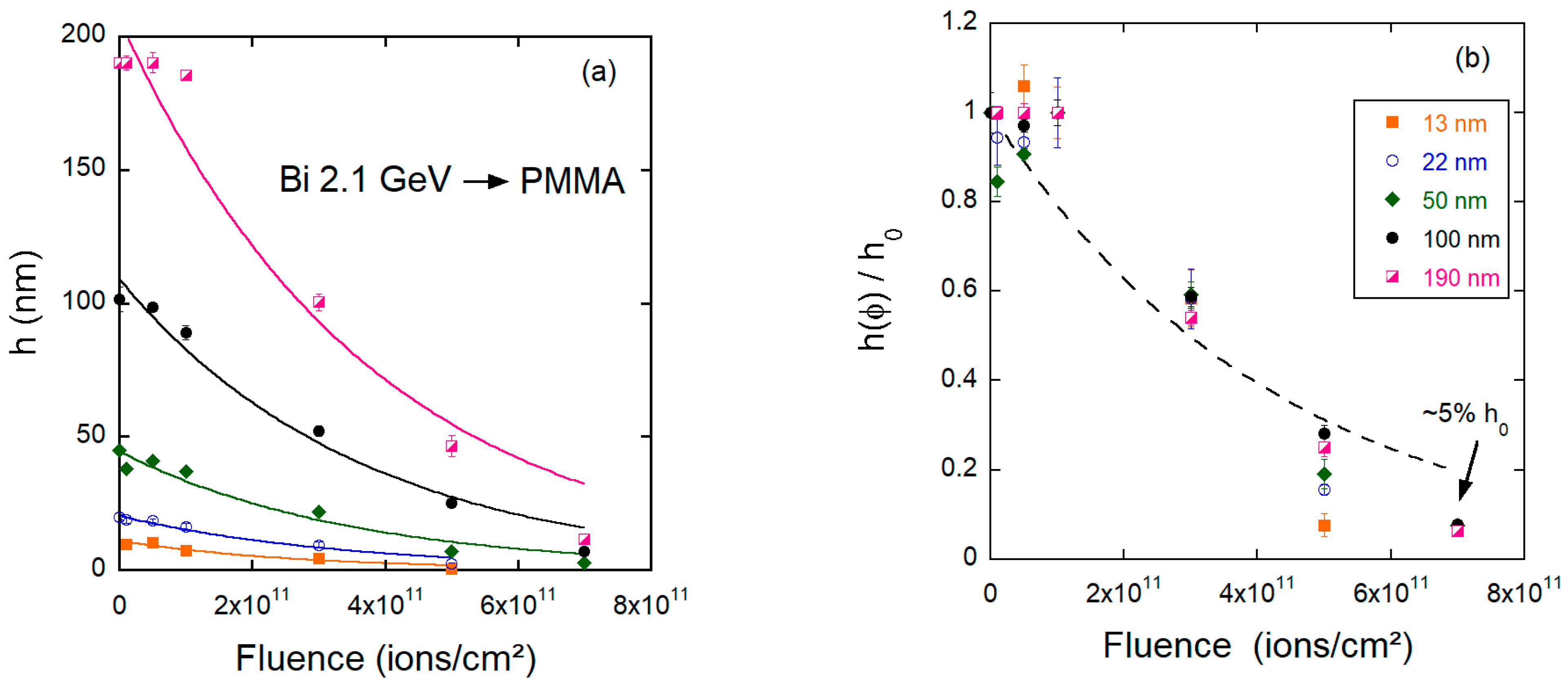
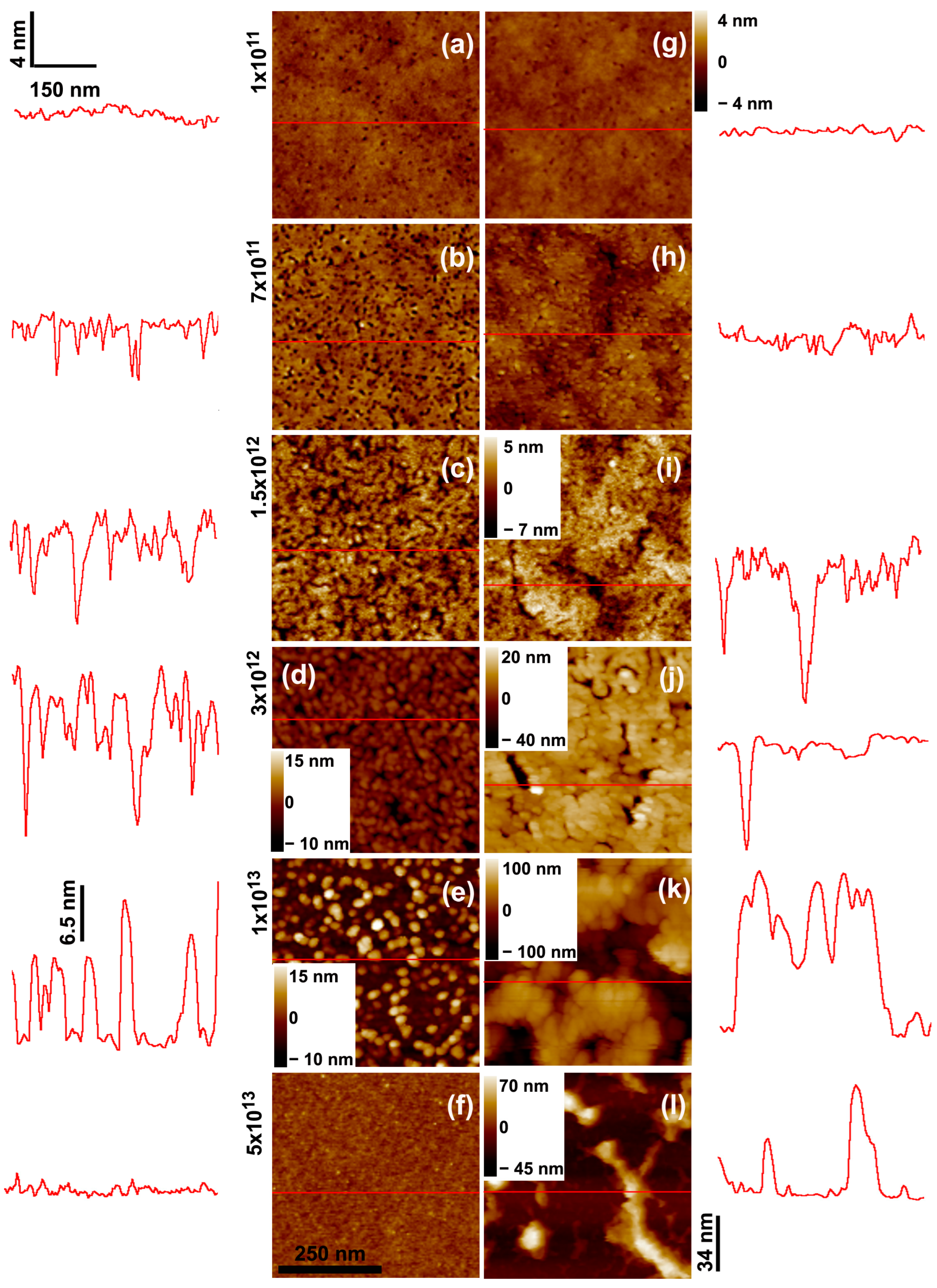
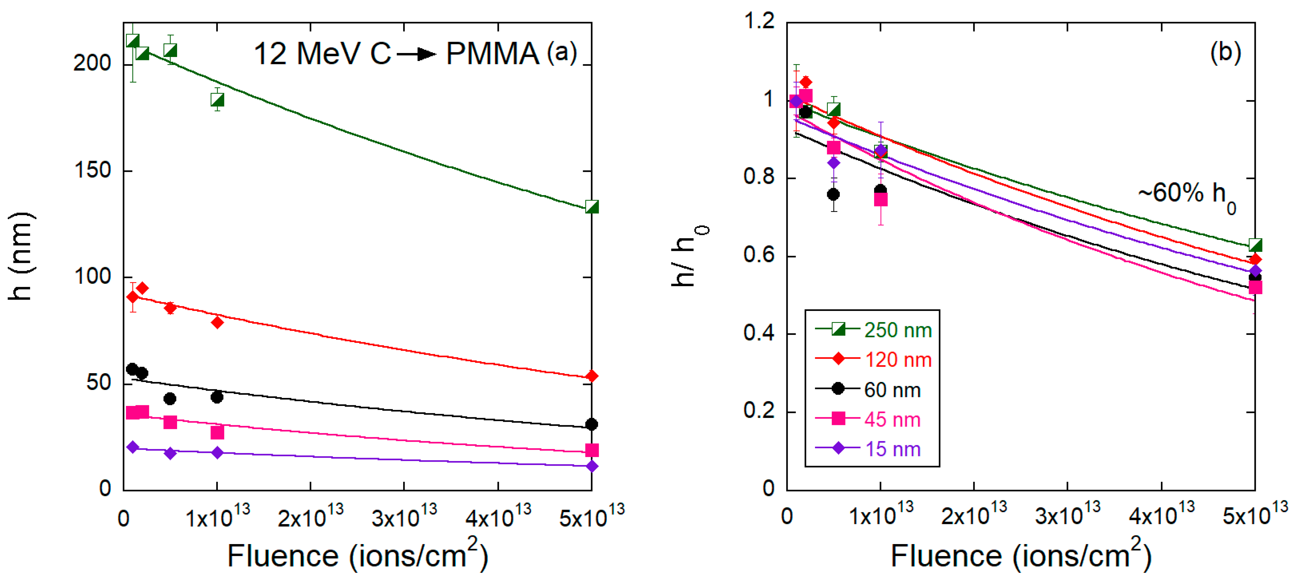
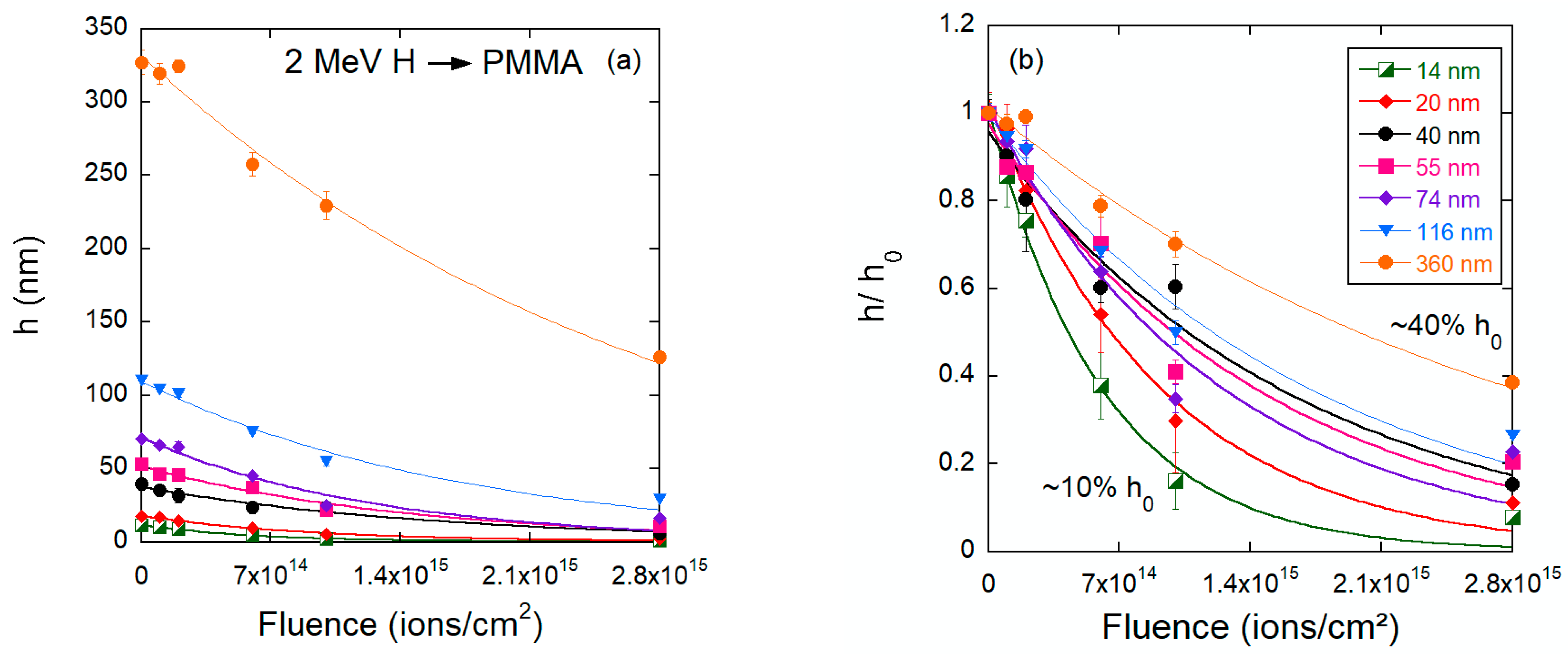
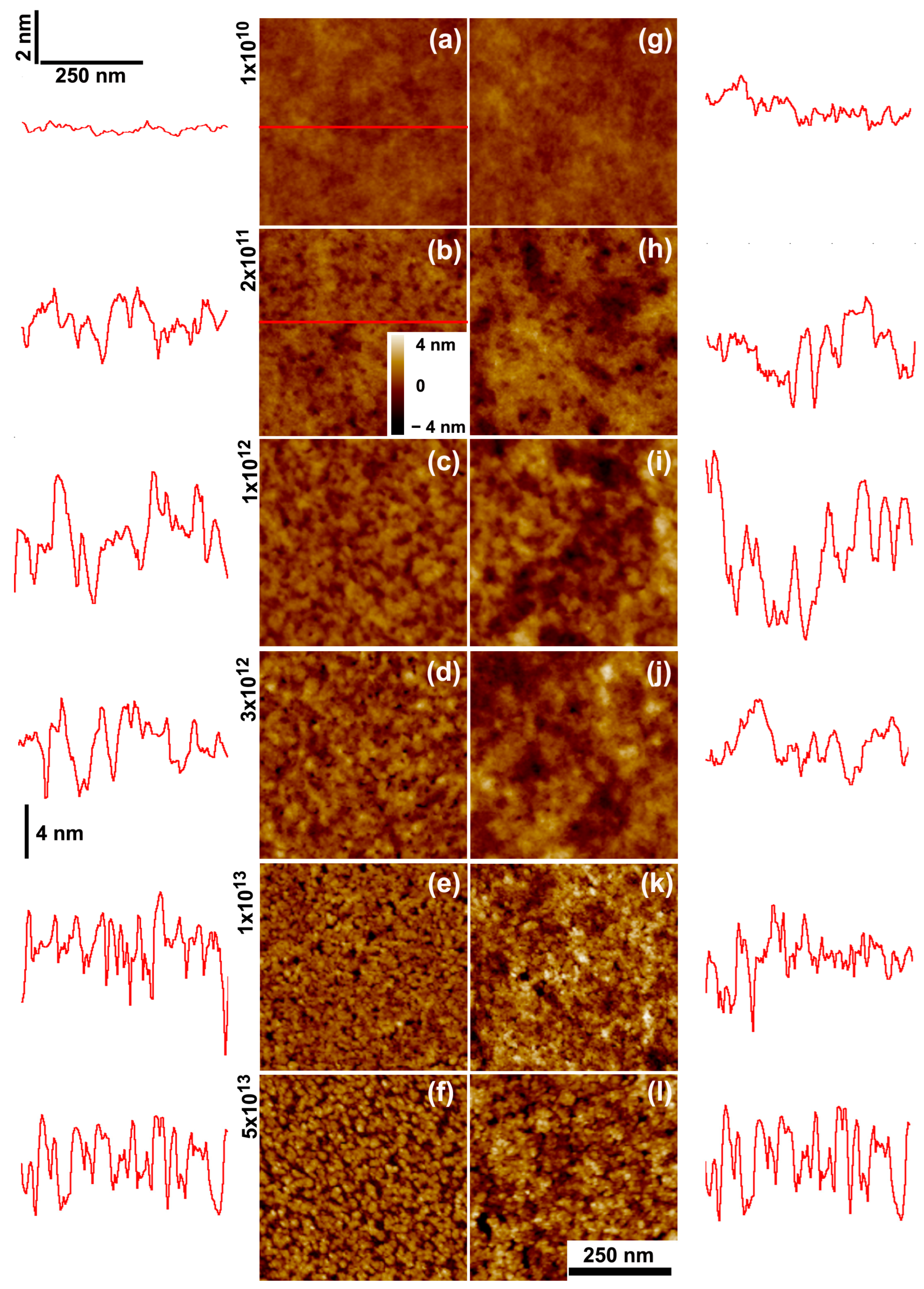
3.1. PMMA Thin Films
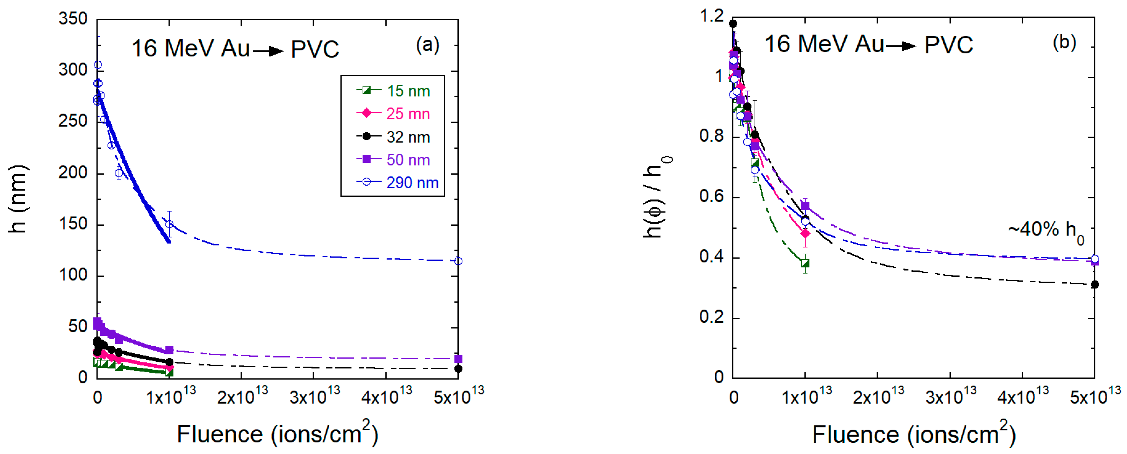
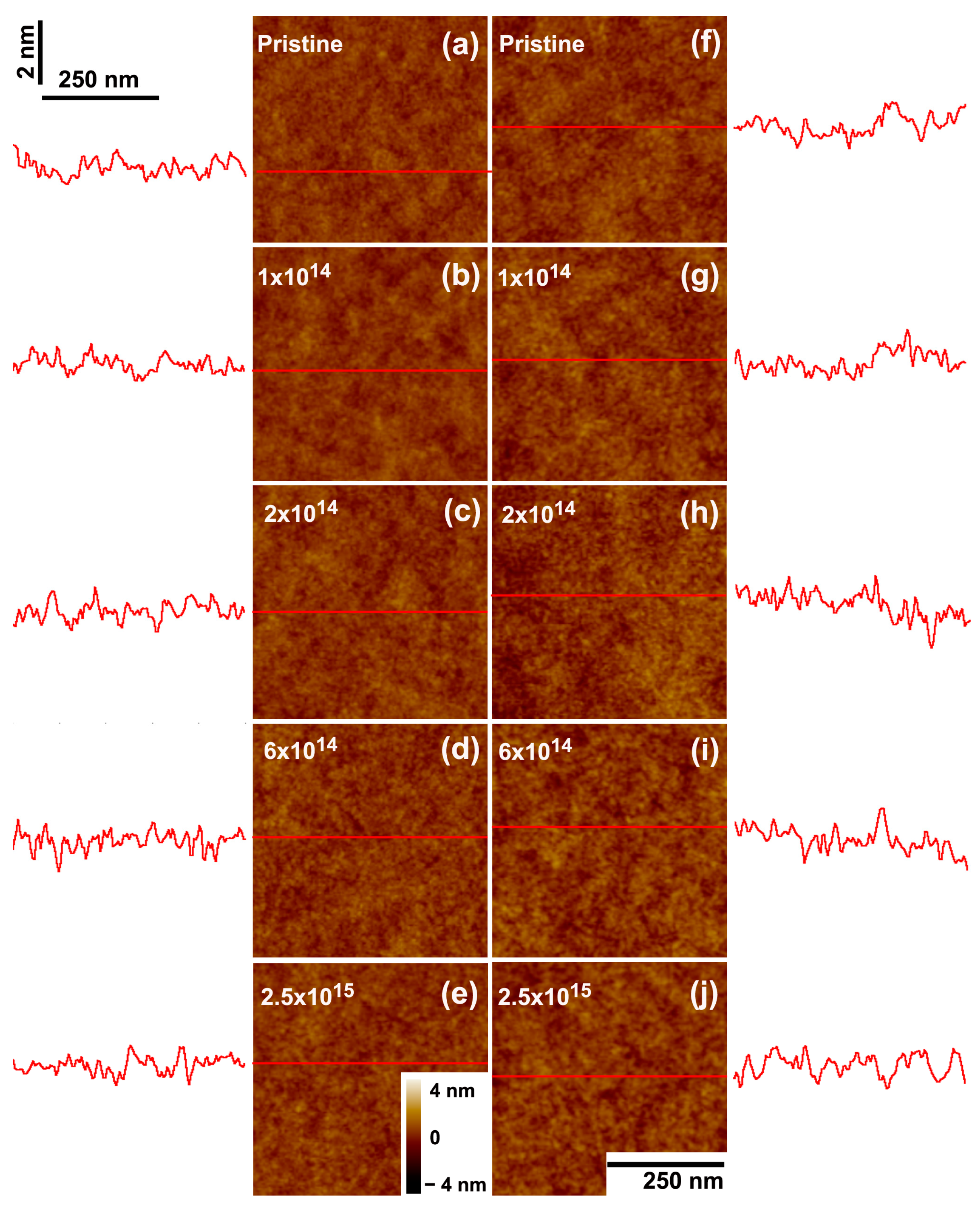
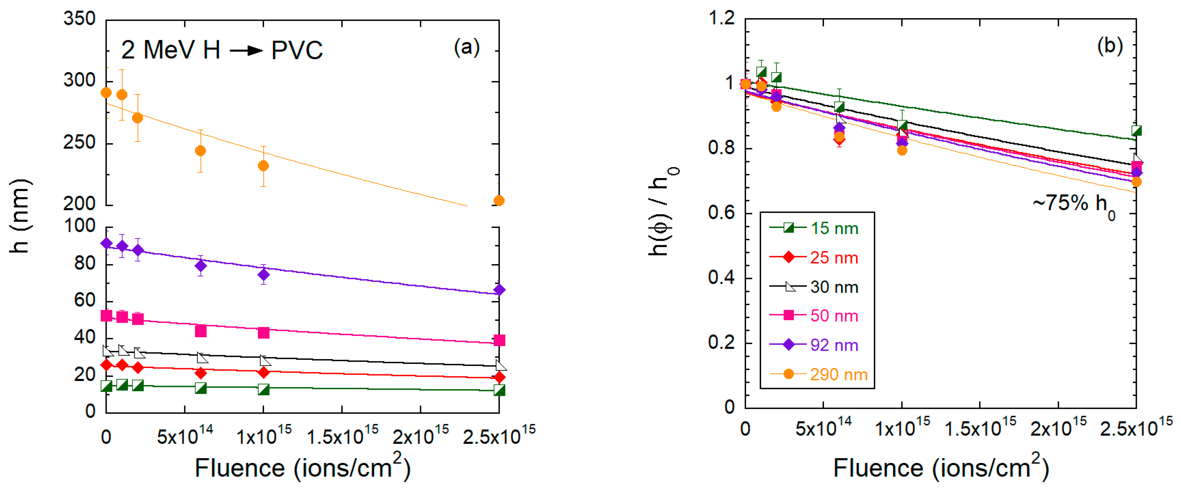
3.2. PVC Thin Films
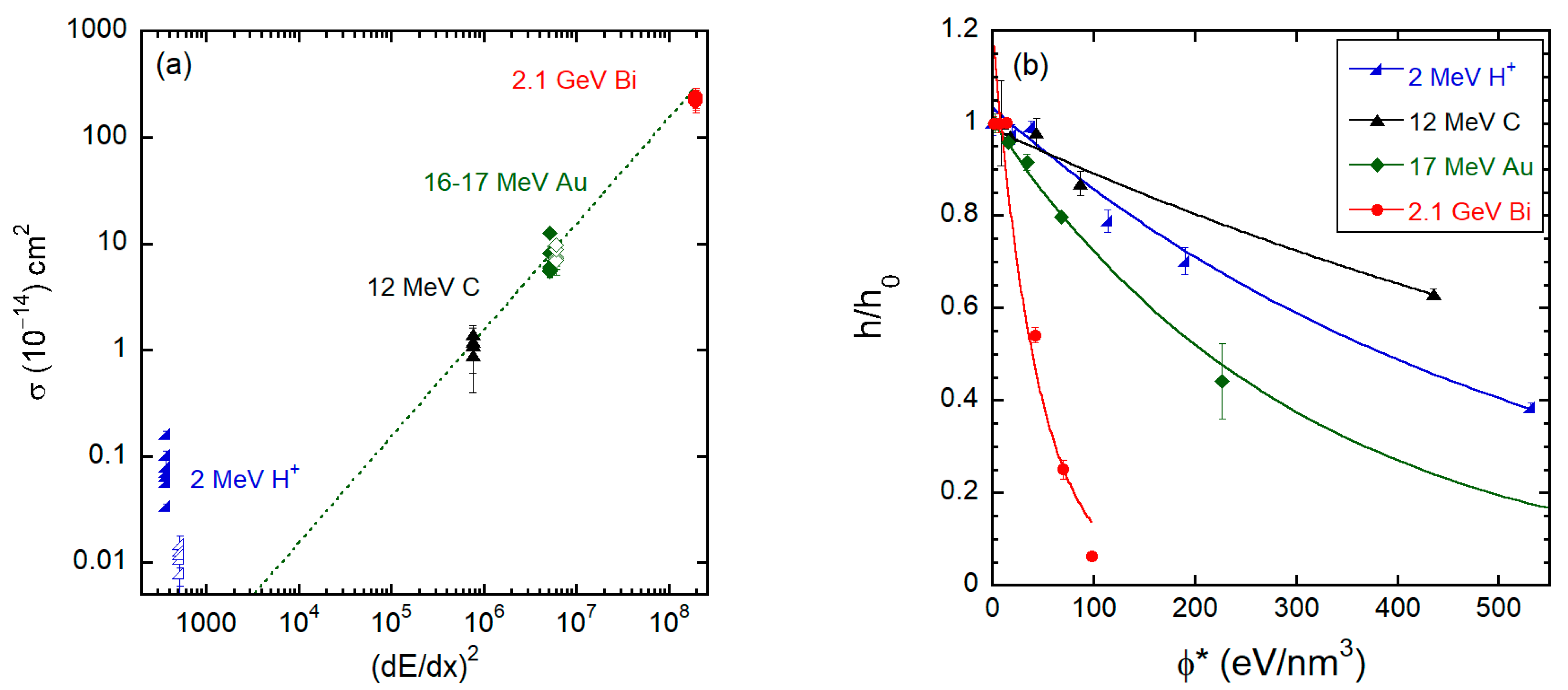
4. Discussion
5. Conclusions
Author Contributions
Funding
Institutional Review Board Statement
Data Availability Statement
Acknowledgments
Conflicts of Interest
References
- Schrempel, F.; Kim, Y.S.; Witthuhn, W. Deep ion beam lithography in PMMA: Irradiation effects. Appl. Surf. Sci. 2002, 189, 102–112. [Google Scholar] [CrossRef]
- Schrempel, F.; Witthuhn, W. Deep light ion lithography in PMMA—A parameter study. Nucl. Instrum. Methods Phys. Res. B 1997, 132, 430–438. [Google Scholar] [CrossRef]
- Ruck, D.M.; Schulz, J.; Deusch, N. Ion irradiation induced chemical changes of polymers used for optical applications. Nucl. Instrum. Methods Phys. Res. B 1997, 131, 149–158. [Google Scholar] [CrossRef]
- Lee, E.H. Ion-beam modification of polymeric materials—Fundamental principles and applications. Nucl. Instrum. Methods Phys. Res. B 1999, 151, 29–41. [Google Scholar] [CrossRef]
- Sum, T.C.; Bettiol, A.A.; Florea, C.; Watt, E. Proton-beam writing of poly-methylmethacrylate buried channel waveguides. J. Light. Technol. 2006, 24, 3803–3809. [Google Scholar] [CrossRef]
- Szilasi, S.Z.; Kokavecz, J.; Huszank, R.; Rajta, I. Compaction of poly(dimethylsiloxane) (PDMS) due to proton beam irradiation. Appl. Surf. Sci. 2011, 257, 4612–4615. [Google Scholar] [CrossRef]
- Yu, J.; Tao, X.; Tam, H.; Demokan, M.S. Modulation of refractive index and thickness of poly(methyl methacrylate) thin films with UV irradiation and heat treatment. Appl. Surf. Sci. 2005, 252, 1283–1292. [Google Scholar] [CrossRef]
- Ruck, D.M. Ion induced modification of polymers at energies between 100 keV and 1 GeV applied for optical waveguides and improved metal adhesion. Nucl. Instrum. Methods Phys. Res. B 2000, 166, 602–609. [Google Scholar] [CrossRef]
- Hong, W.; Woo, H.J.; Choi, H.W.; Kim, Y.S.; Kim, G.D. Optical property modification of PMMA by ion-beam implantation. Appl. Surf. Sci. 2001, 169, 428–432. [Google Scholar] [CrossRef]
- Wochnowski, C.; Metev, S.; Sepold, G. UV-laser-assisted modification of the optical properties of polymethylmethacrylate. Appl. Surf. Sci. 2000, 154, 706–711. [Google Scholar] [CrossRef]
- Sum, T.C.; Bettiol, A.A.; van Kan, J.A.; Watt, F.; Pun, E.Y.B.; Tung, K.K. Proton beam writing of low-loss polymer optical waveguides. Appl. Phys. Lett. 2003, 83, 1707–1709. [Google Scholar] [CrossRef]
- Licciardello, A.; Fragalà, M.E.; Compagnini, G.; Puglisi, O. Cross section of ion polymer interaction used to individuate single track regime. Nucl. Instrum. Methods Phys. Res. B 1997, 122, 589–593. [Google Scholar] [CrossRef]
- Rück, D.M.; Brunner, S.; Frank, W.; Kulisch, J.; Franke, H. Optical waveguides in polymeric material by ion implantation. Surf. Coat. Technol. 1992, 51, 318–323. [Google Scholar] [CrossRef]
- Rickards, J.; Zironi, E.P. Chlorine loss from polyvinyl chloride under proton bombardment. Nucl. Instrum. Methods Phys. Res. B 1991, 56–57, 687–689. [Google Scholar] [CrossRef]
- Cota, L.; Adem, E.; Yacamán, M.J. Interaction of an electron beam with a polymer surface: Study of polyvinyl chloride (PVC) using auger electron spectroscopy. Appl. Surf. Sci. 1986, 27, 106–113. [Google Scholar] [CrossRef]
- Adem, E.; Avalos-Borja, M.; Rickards, J.; Trejo-Luna, R. Microcrystals formed in proton bombarded poly(vinyl chloride) films. Radiat. Phys. Chem. 1996, 48, 727–730. [Google Scholar] [CrossRef]
- Chakraborty, R.N.; Srivastava, A.K.; Singh, B.K.; Pathak, R.; Chaturvedi, U.K.; Nigam, A.K. Effect of HCl vapours due to PVC, on PVDF samples during 250 keV H+ ion implantation. Nucl. Instrum. Methods Phys. Res. B 1991, 62, 239–241. [Google Scholar] [CrossRef]
- Davenas, J.; Tran, V.H.; Boiteux, G. Ion beam induced conversion of PVC into a conducting polyene. In Proceedings of the International Conference on Science and Technology of Synthetic Metals, Seoul, Republic of Korea, 24–29 July 1994; p. 310. [Google Scholar]
- Venkatesan, T.; Forrest, S.R.; Kaplan, M.L.; Murray, C.A.; Schmidt, P.H.; Wilkens, B.J. Ion-beam-induced conductivity in polymer films. J. Appl. Phys. 1983, 54, 3150–3153. [Google Scholar] [CrossRef]
- Thomaz, R.; Louette, P.; Hoff, G.; Muller, S.; Pireaux, J.J.; Trautmann, C.; Papaléo, R.M. Bond-Breaking Efficiency of High-Energy Ions in Ultrathin Polymer Films. Phys. Rev. Lett. 2018, 121, 066101. [Google Scholar] [CrossRef] [PubMed]
- Rickards, J.; Trejo-Luna, R.; Andrade, E. PVC film behavior under proton bombardment. Radiat. Phys. Chem. 1995, 45, 629–636. [Google Scholar] [CrossRef]
- Davenas, J.; Thevenard, P.; Boiteux, G.; Fallavier, M.; Lu, X.L. Hydrogenated carbon layers produced by ion beam irradiation of PMMA and polystyrene films. Nucl. Instrum. Methods Phys. Res. B 1990, 46, 317–323. [Google Scholar] [CrossRef]
- Zaporojtchenko, V.; Zekonyte, J.; Erichsen, J.; Faupel, F. Etching rate and structural modification of polymer films during low energy ion irradiation. Nucl. Instrum. Methods Phys. Res. B 2003, 208, 155–160. [Google Scholar] [CrossRef]
- Zekonyte, J.; Zaporojtchenko, V.; Faupel, F. Investigation of the drastic change in the sputter rate of polymers at low ion fluence. Nucl. Instrum. Methods Phys. Res. B 2005, 236, 241–248. [Google Scholar] [CrossRef]
- Ziegler, J.F.; Ziegler, M.D.; Biersack, J.P. SRIM—The stopping and range of ions in matter (2010). Nucl. Instrum. Methods Phys. Res. B 2010, 268, 1818–1823. [Google Scholar] [CrossRef]
- Papaléo, R.M.; Thomaz, R.; Gutierres, L.I.; de Menezes, V.M.; Severin, D.; Trautmann, C.; Tramontina, D.; Bringa, E.M.; Grande, P.L. Confinement Effects of Ion Tracks in Ultrathin Polymer Films. Phys. Rev. Lett. 2015, 114, 118302. [Google Scholar] [CrossRef] [PubMed]
- Choi, H.W.; Woo, H.J.; Hong, W.; Kim, J.K.; Lee, S.K.; Eum, C.H. Structural modification of poly(methyl methacrylate) by proton irradiation. Appl. Surf. Sci. 2001, 169, 433–437. [Google Scholar] [CrossRef]
- Thomaz, R.; Gutierres, L.I.; Morais, J.; Louette, P.; Severin, D.; Trautmann, C.; Pireaux, J.J.; Papaléo, R.M. Oxygen loss induced by swift heavy ions of low and high dE/dx in PMMA thin films. Nucl. Instrum. Methods Phys. Res. B 2015, 365, 578–582. [Google Scholar] [CrossRef]
- Bringa, E.M.; Johnson, R.E.; Papaleo, R.M. Crater formation by single ions in the electronic stopping regime: Comparison of molecular dynamics simulations with experiments on organic films. Phys. Rev. B 2002, 65, 094113. [Google Scholar] [CrossRef]
- Sum, T.C.; Bettiol, A.A.; Seng, H.L.; Rajta, I.; van Kan, J.A.; Watt, F. Proton beam writing of passive waveguides in PMMA. Nucl. Instrum. Methods Phys. Res. B 2003, 210, 266–271. [Google Scholar] [CrossRef]
- Choi, J.O.; Moore, J.A.; Corelli, J.C.; Silverman, J.P.; Bakhru, H. Degradation of poly(methylmethacrylate) by deep ultraviolet, x-ray, electron beam, and proton beam irradiations. J. Vac. Sci. Technol. B 1988, 6, 2286. [Google Scholar] [CrossRef]
- Kaczmarek, H.; Chaberska, H. The influence of UV- irradiation and support type on surface properties of poly(methyl methacrylate) thin films. Appl. Surf. Sci. 2006, 252, 8185–8192. [Google Scholar] [CrossRef]
- Ventura, A.; Ngono-Ravache, Y.; Marie, H.; Levavasseur-Marie, D.; Legay, R.; Dauvois, V.; Chenal, T.; Visseaux, M.; Balanzat, E. Hydrogen Emission and Macromolecular Radiation-Induced Defects in Polyethylene Irradiated under an Inert Atmosphere: The Role of Energy Transfers toward trans-Vinylene Unsaturations. J. Phys. Chem. B 2016, 120, 10367–10380. [Google Scholar] [CrossRef]
- Ferry, M.; Ngono, Y. Energy transfer in polymers submitted to ionizing radiation: A review. Radiat. Phys. Chem. 2021, 180, 109320. [Google Scholar] [CrossRef]


| Ion | Polymer | (dE/dx)e [eV/nm] | (dE/dx)n [eV/nm] | Rp [µm] | (ions/cm2) | (eV/nm3) |
|---|---|---|---|---|---|---|
| 2 MeV H+ | PVC | 22.8 | 0.015 | 53.3 | 1014 to 2.8 × 10¹⁵ | 23 to 640 |
| 2 MeV H+ | PMMA | 19.2 | 0.013 | 64.2 | 1014 to 2.5 × 10¹⁵ | 19 to 480 |
| 12 MeV C | PMMA | 871 | 0.79 | 13.7 | 1012 to 5 × 10¹³ | 9 to 435 |
| 16 MeV Au | PVC | 2468 | 691 | 5.23 | 1010 to 5 × 10¹³ | 0.2 to 1230 |
| 17 MeV Au | PMMA | 2270 | 561 | 6.07 | 1011 to 5 × 10¹³ | 2.3 to 1130 |
| 2.2 GeV Bi | PMMA | 14,010 | 13.9 | 159 | 1010 to 7 × 10¹¹ | 1.4 to 98 |
| 2.1 GeV Bi | 17 MeV Au | 12 MeV C | 2 MeV H+ | ||||
|---|---|---|---|---|---|---|---|
| (nm) | (10−12) [cm2] | (nm) | (10−14) [cm2] | (nm) | (10−14) [cm2] | (nm) | (10−16) [cm2] |
| 190 | 2.3 0.5 | 800 | 6.0 0.8 | 250 | 0.9 | 360 | 3.4 0.2 |
| 100 | 2.2 0.4 | 400 | 5.5 0.7 | 120 | 1.1 | 116 | 5.7 0.5 |
| 50 | 2.4 0.5 | 200 | 8.2 1.3 | 60 | 1.2 | 74 | 8.0 1.5 |
| 22 | 2.2 0.5 | 90 | 5.8 | 45 | 1.4 0.3 | 55 | 7.1 0.7 |
| 13 | 2.3 1.0 | 40 | 5.6 0.7 | 15 | 1.1 0.3 | 40 | 6.6 0.8 |
| - | - | 25 | 12.5 0.3 | - | - | 20 | 10.4 0.8 |
| - | - | - | - | - | - | 14 | 16.2 1.1 |
| 16 MeV Au | 2 MeV H+ | ||
|---|---|---|---|
| (nm) | (10−14) [cm2] | (nm) | (10−16) [cm2] |
| 290 | 7.5 1.8 | 290 | 1.5 0.3 |
| 50 | 7.2 1.0 | 92 | 1.3 |
| 32 | 6.9 1.8 | 50 | 1.2 0.3 |
| 25 | 8.8 0.9 | 30 | 1.1 0.2 |
| 15 | 9.7 1.1 | 25 | 1.2 0.6 |
| 15 | 0.8 0.3 | ||
Disclaimer/Publisher’s Note: The statements, opinions and data contained in all publications are solely those of the individual author(s) and contributor(s) and not of MDPI and/or the editor(s). MDPI and/or the editor(s) disclaim responsibility for any injury to people or property resulting from any ideas, methods, instructions or products referred to in the content. |
© 2023 by the authors. Licensee MDPI, Basel, Switzerland. This article is an open access article distributed under the terms and conditions of the Creative Commons Attribution (CC BY) license (https://creativecommons.org/licenses/by/4.0/).
Share and Cite
Thomaz, R.; Ngono-Ravache, Y.; Severin, D.; Trautmann, C.; Papaléo, R.M. Thinning of Poly(methyl methacrylate) and Poly(vinyl chloride) Thin Films Induced by High-Energy Ions of Different Stopping Powers. Polymers 2023, 15, 4471. https://doi.org/10.3390/polym15234471
Thomaz R, Ngono-Ravache Y, Severin D, Trautmann C, Papaléo RM. Thinning of Poly(methyl methacrylate) and Poly(vinyl chloride) Thin Films Induced by High-Energy Ions of Different Stopping Powers. Polymers. 2023; 15(23):4471. https://doi.org/10.3390/polym15234471
Chicago/Turabian StyleThomaz, Raquel, Yvette Ngono-Ravache, Daniel Severin, Christina Trautmann, and Ricardo M. Papaléo. 2023. "Thinning of Poly(methyl methacrylate) and Poly(vinyl chloride) Thin Films Induced by High-Energy Ions of Different Stopping Powers" Polymers 15, no. 23: 4471. https://doi.org/10.3390/polym15234471
APA StyleThomaz, R., Ngono-Ravache, Y., Severin, D., Trautmann, C., & Papaléo, R. M. (2023). Thinning of Poly(methyl methacrylate) and Poly(vinyl chloride) Thin Films Induced by High-Energy Ions of Different Stopping Powers. Polymers, 15(23), 4471. https://doi.org/10.3390/polym15234471