Review

Recent Advances in Flexible Piezoresistive Arrays: Materials, Design, and Applications

1
School of Integrated Circuit, Tsinghua University, Beijing 100084, China
2
Beijing National Research Center for Information Science and Technology (BNRist), Tsinghua University, Beijing 100084, China
3
Center for Flexible Electronics Technology, Tsinghua University, Beijing 100084, China
*
Authors to whom correspondence should be addressed.
These authors contributed equally to this work.
Polymers 2023, 15(12), 2699; https://doi.org/10.3390/polym15122699
Submission received: 18 May 2023 / Revised: 6 June 2023 / Accepted: 7 June 2023 / Published: 16 June 2023

Abstract

:
Spatial distribution perception has become an important trend for flexible pressure sensors, which endows wearable health devices, bionic robots, and human–machine interactive interfaces (HMI) with more precise tactile perception capabilities. Flexible pressure sensor arrays can monitor and extract abundant health information to assist in medical detection and diagnosis. Bionic robots and HMI with higher tactile perception abilities will maximize the freedom of human hands. Flexible arrays based on piezoresistive mechanisms have been extensively researched due to the high performance of pressure-sensing properties and simple readout principles. This review summarizes multiple considerations in the design of flexible piezoresistive arrays and recent advances in their development. First, frequently used piezoresistive materials and microstructures are introduced in which various strategies to improve sensor performance are presented. Second, pressure sensor arrays with spatial distribution perception capability are discussed emphatically. Crosstalk is a particular concern for sensor arrays, where mechanical and electrical sources of crosstalk issues and the corresponding solutions are highlighted. Third, several processing methods are also introduced, classified as printing, field-assisted and laser-assisted fabrication. Next, the representative application works of flexible piezoresistive arrays are provided, including human-interactive systems, healthcare devices, and some other scenarios. Finally, outlooks on the development of piezoresistive arrays are given.

1. Introduction

Pressure sensing is indispensable in a wide range of scenarios, e.g., physiological signal detection, environmental signal monitoring, etc. The rigid single-point sensor, such as load cells, have been maturely applied with high accuracy and stability for decades, integrated with dedicated designs. However, their large volume limits their spatial arrangement and installation. With the development of micro/nanomaterials and design strategies, endowing pressure sensors with flexibility and high spatial resolution properties have been hot research topics over the years, which not only are essentials in frontier scientific and technological fields (e.g., robotic tactile perception and prosthesis [1,2], human-interactive interfaces [3,4], wearable healthcare devices [5,6], etc.) but also have the potential as an alternative and complement to traditional single-point sensors. Flexibility enables easy and fine attachment on curved surfaces and less discomfort for biological measurement. The arrayed structure provides spatial pressure distribution, thus being able to extract abundant information. There are multiple mechanisms for flexible pressure sensing arrays that convert pressure into different electrical quantities, including piezoresistive [7,8], capacitive [9,10], piezoelectric [11,12], triboelectric [13,14], etc. Among them, piezoelectric and triboelectric sensors demonstrate high sensitivity to dynamic pressure; however, they have more complicated electronic designs and suffer from inaccuracy when measuring static pressure. For measurements including both static and dynamic pressure, capacitive sensors and piezoresistive sensors are mostly preferred. Although capacitive sensors can achieve high sensitivity and stability, they are susceptible to parasitic capacitance and noise. In comparison, piezoresistive sensors have the advantages of easy material preparation, simple readout circuits, low-cost, and anti-electrical interference capacity in measurements.
In recent years, many studies on flexible piezoresistive sensors have been published, with new materials and structures developed to improve sensor performance. For the design and manufacture of flexible arrays, it is not just a matter of spatially arranging measuring points. It is necessary to comprehensively consider the problems that may be encountered, especially the crosstalk problem after arraying, which will lead to the mutual influence of signals between measuring points, causing the actual spatial resolution to be lower than the spacing of the array elements. Furthermore, many manufacturing methods in laboratory studies are based on manual methods, which limits their mass production, so more automation and mature equipment processes need to be introduced to promote the application of piezoresistive arrays.
Aiming to summarize and provide comprehensive ideas for developing the flexible piezoresistive array, this review is presented. The content of this review ranges from piezoresistive materials and microstructures, array design and fabrication, to applications and outlooks. Section 2 focuses on piezoresistive materials and microstructure design. After introducing the performance metrics of pressure sensors, design strategies for performance improvement are discussed in detail. Section 3 focuses on piezoresistive array design and fabrication. According to the resistance readout strategy, i.e., whether active components are integrated with the material, piezoresistive sensor arrays are divided into passive and active arrays. Different structure designs and measuring methods that are capable of providing spatial pressure information are reviewed. There are two main structural forms: one is to arrange multiple independent measurement unit materials and use each piece of material as a measurement point; the other is to make arrayed electrodes on a whole piece of sensitive material and make the electrode intersection point as a measuring point. In addition to the above two forms, other methods, such as visible output and electrical impedance tomography, are also briefly introduced. The crosstalk problem is crucial for the accuracy of spatial measurement. Sources of crosstalk are discussed, including both mechanical and electrical crosstalk. Corresponding suppression approaches include ideas from structure design to readout circuit design. Several fabrication strategies that are promising for mass production are also summarized, consisting of printing, field-assisted processing, and laser-assisted processing. The pressure distribution measured by the sensor device can further provide different information and functions in different application fields. In Section 4, the discussion further focuses on the information that can be extracted from the signals and how they can be used for actual applications, including human-interactive systems, healthcare, and other scenarios. Finally, some outlooks for the development of piezoresistive arrays are provided in Section 5.

2. Piezoresistive Materials and Microstructures

2.1. Performance Metrics of Pressure Sensors

The evaluation of pressure sensors requires a series of performance metrics, including sensitivity, working range, linearity, hysteresis, response time, relaxation time, and spatial resolution [15]. These indicators are important for understanding the physical properties of the sensor and the sensor selection for specific scene requirements.
The sensitivity of the piezoresistive pressure sensor is defined as the slope of the relative change in resistance or current versus pressure. The quantitative description of sensitivity is as follows, having the unit kPa−1 or Pa−1.
S = δ ( R R 0 R 0 ) δ P   or   S = δ ( I I 0 I 0 ) δ P
In general, the sensitivity of many pressure sensors decreases with pressure, and the resistive response saturates beyond the working range; thus, maintaining high sensitivity and linearity over a wide pressure range is an important issue.
Hysteresis influences measurement inaccuracy, manifested as the variation between the loading curve and the unloading curve. The quantitative indicator of hysteresis is defined as
| A u n l o a d i n g A l o a d i n g A l o a d i n g | × 100 %   or   | Δ H m a x y F S | × 100 %
where   A u n l o a d i n g and   A l o a d i n g are the areas under the unloading and loading curve [16,17], Δ H m a x is the maximum difference between the loading and unloading curve at the same pressure, and is the full-scale output [15,18,19]. The intrinsic cause of the hysteresis phenomenon includes viscoelasticity of the material, adhesion between the conductive material and substrate, etc. Additionally, most piezoresistive materials based on polymer composite materials have relatively high hysteresis. This is due to the inability of its internal conductive network to fully recover after rearranging under stress [20]. In addition to developing low hysteresis materials, circuitry [21] and algorithms [22] can be applied to compensate for the hysteresis.
Response time and relaxation time (also known as recovery time) are crucial factors for dynamic measurement scenarios. They are used to quantitatively describe the delay of resistance change to pressure change when loading and unloading. Mechanical viscoelasticity is the main cause of the delay [15,23].
For the sensor array, the spatial distribution of measurement points can be characterized by spatial resolution, which is represented in the form of N × N [24], the spatial period of the arrangement (center-to-center distance between adjacent pixels) [25], or the number of measuring points per unit area (in dots per inch or pixels per inch) [26]. A detailed discussion about array design and spatial resolution is presented in Section 3.1.2.

2.2. Piezoresistive Materials and Microstructure Design

Piezoresistive sensors convert pressure into a change in resistance. The resistance can be measured by either sandwiched between the positive and negative electrodes or placed on coplanar electrodes, dominated by either vertical or lateral resistance, respectively. The resistance can be considered as the combination of bulk resistance and contact resistance [27,28]. Bulk resistance is related to material properties, including geometry and internal electrical property. Contact resistance is related to the contact area and interface between the material and the electrodes. To enable sensors with better performance, various materials and sensing structures have been extensively studied.
In terms of piezoresistive materials, besides metal strain gauges and semiconductor devices [7], polymer composite materials have been a focus in the literature [15,29], which shows great prospects in large areas and flexible sensor devices. Polymer composite materials are usually composed of plastic matrix and conductive components. For polymer composites consisting of conductive fillers and insulating substrates, bulk resistance is related to both its geometry and the conductive pathways inside the material, explained by the percolation theory and the tunneling effect [30,31]. The percolation theory analyzes the pressure-induced percolation pathways formed by conductive components, and the tunneling effect refers to the tunneling of charge carriers without contact between particles [7]. Common choices for elastic bases are polymers, e.g., polydimethylsiloxane (PDMS) [32,33], polyurethane (PU) [34], and thermoplastic polyurethane (TPU) [35,36]. Hydrogels [37] are preferred for biocompatible requirements. Conductive components usually include (1) carbon-based materials, e.g., carbon black (CB) [35,38], carbon nanotubes (CNTs) [39,40], graphene [41,42], hybrid carbon fillers [43], etc.; (2) metal materials, e.g., metal nanowires [34,44] and metal particles [26]; (3) others include MXene [45,46], conductive polymers, e.g., polypyrrole (PPy) [16,47], polyaniline (PANI) [48], poly(3,4-ethylene dioxythiophene) (PEDOT) [49], etc. For the electrode material connecting each measurement point of the array, metal materials are usually selected, e.g., Au-based serpentine connections [50] and spay-coated Ag nanowire electrode strips [26]. Adjusting the ratio and concentration of substrates and conductive fillers will lead to different sensor characteristics. Shi et al. reported a pressure sensor with extremely low loading (<1.5 wt.%) of urchin-like hollow carbon spheres in PDMS fabricated by the spin-coating method. The sensor relied on the Fowler–Nordheim tunneling effect, which enabled a large tunneling distance and resulted in an ultrahigh sensitivity of 260.3 kPa−1 at 1 Pa. The minimal amount of filler material also endowed the sensor with desirable properties such as high transparency, high elasticity, biocompatibility, and ease of fabrication. Furthermore, the hollow structure contributed to the resistance to temperature variations [51]. By adjusting the ratio of ink components (which consists of conductive carbon nanotubes, insulating silica nanoparticles, and silicone elastomer polymer), Tang et al. proposed a soft and porous composite pressure sensor fabricated by 3D printing technology which can be tuned between negative and positive piezoresistive effect. At a lower CNTs content, a positive piezoresistive pressure sensor with a sensitivity of 0.096 kPa−1 across a 0~175 kPa pressure range can be produced with good linearity [52].
In addition to the selection and proportion of materials, the performance of sensors can be further improved by designing three-dimensional microstructures on the surface. The microstructures enhance the material’s compressibility and stress concentration in terms of mechanical properties and facilitate changing the contact area of the conductive interface, thereby improving the sensor’s pressure-sensing performance. In terms of specific surface morphology, both regular and irregular microstructures can be applied. Regular surface structures include microdome [53], micropyramid [54], micropillar arrays [55], conical frustum-like surface structures [56], etc., improving the sensitivity by increasing the contact area under pressure. These microstructures can be fabricated by casting or coating onto templates. The templates can be silica molds prepared by photolithography [57], laser engraved mold [58], etc. Additional surface morphology can also be added to the 3D structure for further improvement. For example, Yao et al. developed a piezoresistive sensor with cracked metallic film coated on the micropyramidal elastomer, which exhibited a sensitivity of more than 107 Ω kPa−1 and a low hysteresis of 2.99 ± 1.37% over 0~20 kPa. To create the cracked morphology, they deposited a thin Pt film on PDMS with a micropyramid surface structure and compressed the material. The key to creating regular and annular is by using a soft low-tack adhesive during compression [59]. According to Li et al., the sharp microstructure can be combined with a short electrode channel length to enhance the sensitivity of the piezoresistive pressure sensor. Based on this, they fabricated a sensor with a sharp micropyramid structure and short-channel coplanar Au electrodes (with a channel length of 300 μm and channel width of 1 mm), achieving a sensitivity of 1907.2 kPa−1 in the 0~100 Pa range and 461.5 kPa−1 in the 100~1000 Pa range, as well as a detection limit of 0.075 Pa and a fast response time of 50 μs [53]. To further improve the sensor performance, irregular surface structures attract interest from researchers, including wrinkles [60], plant-inspired structures using natural biomaterial templates (e.g., leaves [46]), and human skin-inspired structures using randomly distributed spinosum templates (e.g., abrasive paper [42]). Additionally, Zhao et al. reported a self-formed microstructure for a piezoresistive film with a surface roughness of about 8~10 μm, which is much smaller than the controllable microstructures (typically 15~100 μm). The piezoresistive film (PRF) was synthesized by mixing multi-walled carbon nanotubes (MWCNTs) with thermoplastic polyurethane (TPU) elastomer at low temperatures [36]. These irregular surface structures generally have higher performance but are not as good as regular structures in terms of controllability, uniformity, and mass production capacity. Further, a multilayer structure can be designed by stacking two layers of microstructure face-to-face, resulting in an interlocked structure. Examples of multilayer structures include both regularly arrayed microstructures [8] and irregular microstructures stacked face-to-face [42], corresponding to the categories of surface morphologies mentioned above.
The internal porous structure is another way to improve sensitivity and working range, owing to its lower modulus and higher compressibility. Preparation strategies include freeze-drying [35], salt or sugar template [61], etc. The pores close when applied with pressure, and the conductive surfaces on the pores contact each other to form conductive paths. Conductive components can be additionally coated to enhance performance. For example, Park et al. fabricated low hysteresis porous piezoresistive material with conductive MWCNTs particles coated at the inner surface of the PDMS pores. They explored both the mechanical and piezoresistive hysteresis of the material with values less than 21.7% and 6.8%, respectively [17]. The pores can have uniform arrangement and size, which enhances the sensor-to-sensor consistency compared to structures with random sizes. Oh et al. presented a piezoresistive sensor with uniform porosity, achieving a coefficient of variation of 2.43%. The microfluidic emulsion droplet self-assembly technique was used to fabricate the porous PDMS elastomer, which exhibited uniformly sized pores arranged in a highly ordered, close-packed manner. They also addressed the problem of bonding strength between elastic substrates and conductive materials by chemically grafting conductive polymer (PPy) on the surface of porous elastomer (PDMS) to establish stronger covalent bonds than physical adhesion, achieving a low hysteresis of 2% [16]. Hierarchical pores can also be applied. Inspired by bamboo, Dai et al. developed a hierarchical pore structure in conductive carbon nanofibers (CNFs)/PDMS foam materials to address the conflict between sensor sensitivity and mechanical reliability in porous structures [62]. The hierarchical pore structures, which consist of large-scale pores of several hundred micrometers, hollow structures of several micrometers, and micro/nanoscale irregular pores on the hollow skeleton, respond to tiny pressures by forming additional conductive paths and exhibit high sensitivity of ~0.6 kPa−1 at 0~1 kPa. The synergy of porous structure and surface microstructure has also been explored. The synergistic effects of the surface microstructure and the porous structure can enhance the contact area and the number of conductive pathways under applied pressure. For example, Li et al. fabricated a piezoresistive material with high porosity and elliptical surface microstructure by using a mixture of PDMS and MWCNTs, stacking two layers to form an interlock structure. The material exhibited a sensitivity of 10.805 kPa−1 in the 1~1000 Pa range and 2.015 kPa−1 in the 1 k~100 kPa range [63].
Figure 1 provides a summary of the material and structure of flexible piezoresistive pressure sensors.

3. Piezoresistive Array Design and Fabrication

3.1. Design

3.1.1. Passive and Active Arrays

At the analog front end, the pressure-modulated resistance array is sequentially scanned and converted to a voltage signal by readout circuitry for further analog-digital conversion. According to the readout method, matrix sensor arrays can be classified into passive and active-matrix arrays [64]. In passive arrays, electrodes are laid directly on the piezoresistive material, while in active arrays, active components (e.g., transistors) are tightly integrated with each pixel element. Active arrays have advantages in signal transduction and integration, but passive arrays are easier to fabricate.
For passive-matrix array construction, electrodes are laid directly on the piezoresistive material. The positive and negative ends can be individually led out for each pixel. For larger array density, a row-column structure is preferable due to the reduced number of wires. Resistors in the same row and column share the same wire. Row lines and column lines are selected sequentially to complete a scan of the whole pressure distribution map (Figure 2A). Signal reading and conditioning are carried out in the external circuit design. A voltage divider, negative-feedback amplifier structure, and Wheatstone bridge are three principles for resistor-voltage conversion. Operational amplifiers can be applied to decrease the output impedance, thus reducing the loading effect [6]. Note that for the row-column mode in the passive matrix, electrical crosstalk may exist inside the array, leading to inaccurate measurement of the resistance. Solutions to this issue will be discussed later in Section 3.1.3. However, they usually involve more operational amplifiers in the circuit design, increasing the hardware volume when higher pixel density is applied. Figure 2B,C presents examples of the passive matrix construction and scanning electronics of commercial products (Tekscan Inc., Norwood, Boston, MA, USA). For the active-matrix array construction, each pixel is integrated with a transistor during fabrication. The pressure-sensitive resistor is connected to a transistor in series. Thin film transistors (TFTs) are common choices for flexible sensors with active matrixes (Figure 2D) [5]. A similar row-column selection method is applied. As shown in Figure 2E [65], the rows are connected to the gates, the columns are connected to the drains, and the sources are connected to the ground resistors. When a pixel transistor is turned on and selected, current flows through the resistor to the ground, generating an output voltage. The electrical crosstalk in the active arrays is reduced compared to the passive arrays. However, the parameters of the transistor, e.g., the on–off state current, affect the allowed range of the sensor resistance.

3.1.2. Structure Designs and Measuring Mechanisms

Spatial resolution is the primary performance metric for evaluating a pressure distribution detection array. There are several structures to measure spatial pressure distribution, and the definition of spatial resolution varies according to the array structure. One direct way is to arrange discrete material elements and corresponding electrodes on substrates. The resolution is commonly reported as the number/density of pixel materials, informs of 3 × 3 [48,52,66], 4 × 4 [8,46,63,67,68], 5 × 5 [62], 6 × 6 [45], and 8 × 8 [25]. An example is shown in Figure 3A [62]. However, the uniformity of pixel property and the gaps between pixels need to be considered [16,69]. For some scenarios, such as decease diagnostic, it is preferable to place individual pressure sensing elements at several feature points (e.g., arches and joints) and interpret the information through further algorithms without a neat row-column array [6]. Another way is to cover the electrodes of the array with a continuous piece of piezoresistive materials to form the array [26,36], which is capable of achieving much higher spatial resolution. Their resolution is often reported as the density of readout points, that is, the density of electrode intersections in passive arrays and the density of transistors in active arrays. For this configuration, the spatial resolution is limited by both the sensing material and the electrodes. For example, Shi et al. developed a pressure sensor based on Fowler–Nordheim tunneling effect by spin-coating urchin-like hollow carbon spheres in polydimethylsiloxane (PDMS) with concentration far below the percolation threshold. The material forms a vertical conduction path under pressure while being horizontally insulated, thereby reducing transverse interference. Theoretically, the sensing density can be 2,718,557 per cm2; however, limited by electrode size, a 64 × 64 passive matrix was fabricated in a 32 × 32 mm area by photolithography, reaching a sensing density of 400 cm−2. The thin-film pressure sensor exhibits a high sensitivity of 260.3 kPa−1, high transparency, and reduced temperature interference (Figure 3B) [51].
Improving resolution while maintaining other good performances is of great importance. As mentioned previously, microstructures commonly involve an increase in sensitivity by introducing variations in the contact area. The size of the microstructure influences pixel density, considering uniformity and flatness. Regular structures (e.g., micropyramids) typically fall in the range of 15~100 μm. Irregular structures based on special molds, such as plants, exhibit better performance but are not suitable for large-scale production; thus, the array demonstrations in these essays are usually individual elements arranged in individual forms. Recently, Zhao et al. developed a large-scale piezoresistive sensor with a high spatial resolution of 0.9 mm (28.2 ppi) by applying a kind of MWCNTs/TPU material with a self-formed surface structure on the scale of 8~10 μm. The microstructure was flat enough for the 0.9 mm pixel size and had a high sensitivity of ~385 kPa. The material was integrated into a 64 × 64 active matrix using CNT TFTs, covering a 4-inch area (Figure 3C) [36]. Researchers also focus on other features, such as air permeability which is required for wearable applications. Pei et al. fabricated a high-resolution array with a porous structure by 3D printing. Silicone ink was extruded by gas to form a porous structure, and graphene was attached to the surface as the piezoresistive material. The sensor had a linear response in the range of 0~12 kPa and a sensitivity of 4 Pa−1. The pitch distance between each sensing unit is 1 mm, equivalent to a resolution of 100 cm−2 (Figure 3D) [70]. Besides higher resolution, multiple resolution, an important sensing characteristic of human skin, was also researched. Mimicking real tactile sensing of human fingers, Kim et al. developed a multiple-resolution piezoresistive sensor by arranging pitch-varying electrodes on a single piece of piezoresistive material. Using aligned Ni/PDMS material, the resolution of their sensor can be adjusted up to 100 dpi with a pitch distance from 0.25 mm to 1 mm (Figure 3E) [26]. In addition to focusing on sensor structure, appropriate processing algorithms will greatly improve the sensing limit under the same hardware conditions [71].
Besides fabricating pixel structures by either assembling discrete material elements or arranging electrodes, there are also pixel-less methods that do not employ patterned pixels on physical structures. One is a light-omitting sensor device with visible output. Lee et al. proposed a two-layer structure consisting of a pressure-sensing film lying on an electroluminescent film capable of displaying high-resolution images corresponding to the pressure distribution. The top film was coated with a kind of cathode and cellulose/nanowire nanohybrid network for pressure sensing, which controls the current flowing through the quantum-dot light-emitting diode on the bottom film, thus influencing the image display. The spatial resolution was over 1000 dpi (evaluated by loading the micro-bumps array). The sensor had a sensitivity of over 5000 kPa−1 and a response time of less than 1 ms. The displayed image was captured by high-resolution cameras in real-time, and the pressure data can be resolved by pre-calibrated image data, which avoided local data acquisition and processing electronics (Figure 3F) [72]. Another is the electrical impedance tomography (EIT) method. It is a technique that can reconstruct the conductivity of the internal area only through electrodes at the boundary. Current is injected into the conductive film, and the voltage is analyzed to reconstruct the impedance distribution [73,74]. An example is shown in Figure 3G [75]. The quality of the result depends largely on the reconstruction algorithm. The EIT method simplifies the internal wiring of the sensing material, thus making it much easier for manufacturing. However, it suffers from poor spatial resolution and low temporal frequency [76].
Figure 3. Structure designs and measuring mechanisms: (A) Example of arranging discrete material elements with 1.0 × 1.0 cm2 pixel size. Reproduced with permission from [62]. Copyright 2021, Elsevier. (B) Quantum effect-based flexible and transparent pressure sensors with a sensing density of 400 cm−2. Reproduced with permission from [51]. Copyright 2020, Springer Nature. (C) A large-scale piezoresistive sensor with a high spatial resolution of 0.9 mm (28.2 ppi) by applying MWCNTs/TPU material with a self-formed surface structure. Reproduced with permission from [36]. Copyright 2022, American Chemical Society. (D) Air permeable pressure sensor array with a resolution of 100 cm−2. Reproduced with permission from [70]. Copyright 2021, Elsevier. (E) A multiple-resolution piezoresistive sensor having a pitch distance from 0.25 mm to 1 mm (up to 100 dpi). Reproduced with permission from [26]. Copyright 2022, American Chemical Society. (F) Light-omitting sensor device with visible output. Reproduced with permission from [72]. Copyright 2020, Springer Nature. (G) Electrical impedance tomography (EIT) method. Reproduced with permission from [76]. Copyright 2020, IEEE.
Polymers 15 02699 g003
In summary, a generic strategy is to attach sensing elements separately to substrates, providing flexible choices for sensor displacement. For pixel-based structures, most previous works stuck at millimeter range resolution with a resolution of no higher than 100 dpi in the literature. This is probably limited by the distance between the conductive path or microstructure size of the material and the fabrication ability of flexible electronics. Pixel-less methods ease the requirement of locally arrayed electronics but involve additional devices or complex algorithm analysis.

3.1.3. Crosstalk and Suppression

It is worth noting that the spatial resolution of the pressure detection array is not only determined by the array structure. All arrays face the challenge of crosstalk. The coupling between the array elements may introduce errors in the pressure measurement of each point, known as crosstalk interference. Thus, for the evaluation of the sensor array, it is necessary to determine maximum resolution under the condition that interference among pixels falls below a certain level [26] and to reduce crosstalk to achieve higher measurement accuracy.
Since both the mechanical and electrical response of each sensing pixel may be influenced by other pixels, the sources of crosstalk issues can be categorized into mechanical crosstalk and electrical crosstalk [25]. Mechanical crosstalk is derived from deformation coupling. A force applied to one pixel would generate deformation of the adjacent pixels, resulting in the resistance change in the unloaded pixels. This is a noteworthy problem for the common sensor structure that covers a whole piece of piezoresistive material on arrayed electrodes [77]. Arranging discrete sensing elements is a direct solution [33], but the elastic supporting layer may still be a cause. To evaluate this issue, Li et al. studied three interconnection methods: serpentine, straight line, and unpatterned piece. They found that serpentine interconnects could best suppress crosstalk between adjacent pixels (Figure 4A) [25]. Electrical crosstalk was caused by unintended conductive pathways or current leakage, resulting in an inaccurate readout of the resistance. The electrical crosstalk paths have two sources. One is the lateral conductive path inside the material at different measuring points, and the other is the crosstalk loop of the external resistance reading circuit of the material. A detailed introduction and countermeasures are presented in the following paragraphs.
For the first condition, an isolated piezoresistive pixel structure can be applied [50,78]. Coplanar electrodes, such as comb structures, can also suppress crosstalk [25,33]. Apart from attaching individual sensing elements, researchers also find some solutions by designing special geometry structures. Park et al. introduced a grooved structure between parallel electrodes through the molding process, which increased the leakage resistance between adjacent electrodes, thus effectively attenuating the crosstalk interference (Figure 4B) [17]. Kyubin Bae et al. further developed a mesh-structured anisotropic material to reduce lateral conduction sensor array using the dip-coating method. The CNT/PDMS composite was uniformly patterned in the holes and isolated by the mesh layer, eliminating the electrical crosstalk effect and mechanically connecting the sensing elements (Figure 4C) [79]. From the perspective of developing new material, Kim et al. presented an anisotropic material to reduce lateral conduction. They prepared Ni/PDMS mixture and applied a magnetic field to align the nickel particles in the field direction, forming filamentous conduction paths. They discovered that after alignment, the composite had less densely connected conduction paths in the lateral direction. There was virtually no crosstalk at pitches beyond 0.25 mm, achieving tunable resolutions up to 100 dpi (Figure 4D) [26].
For the second condition, array indexing is commonly applied for reading out large sensor arrays, requiring only m + n electrodes. However, since each sensing element is not insulated, this row-column selection method would introduce unintended loops. For example, as shown in Figure 4E [80], in order to read the resistance of R22, the driving voltage was applied at the second row, and the generated voltage was read out at the terminal of the second column. This can lead to unintended currents flowing through the path, shown by the dashed line, which causes inaccuracy of the result. One way to solve the problem is to insert control devices, such as transistors, into the array. Tanaka et al. [81] introduced transistors to choose the sensitive elements and realized a 128 × 128 resistive bolometer array with a scanning rate of 30 Hz. Diode can also be used to control the elements. By placing each element in series with the diode, the parasitic parallel current was suppressed by the single guiding pass of the diode. A high readout rate can be achieved; however, the measurement accuracy is deeply affected by the parameter of the inserting devices, which are susceptible to multiple environmental factors. In addition, the complex construction adds to the complexity and cost of manufacturing. Another way is to build an external circuit to gate the sensing element and short the unselected elements to attenuate the influence of the unintended loops. To eliminate the crosstalk, different measurement methods were applied, such as the voltage feedback methods (VFM) and the zero potential methods (ZPM). The application of VFM was introduced by Tise [82], who realized a 16 × 16 piezoresistive sensor array with a scanning rate of 10 Hz. As shown in Figure 4F [83], the output voltage is feedback to column wires and row wires through an operational amplifier. The voltage drop of nonscanned elements was very small. The idea of ZPM is illustrated in Figure 4G [84]; the output of each column is connected in series with an operational amplifier whose purpose is to set the voltage Vref at the tracks of all columns. Since the voltage of all rows that do not contribute to the output is also set to Vref, all of the unintended loops are short-circuited. Both VFM and ZPM have the advantages of high accuracy, fast readout rate, and low interconnection complexity; however, they lead to an increase in the circuit volume. The algorithmic correction method determines the sensor resistance by establishing and solving the resistance matrix equations of the sensor array, avoiding dedicated hardware design. Shu et al. realized a 10 × 10 tactile resistive sensor array with a scanning rate of 30 Hz and a measurement accuracy of 0.61 ± 0.41% [85]. Algorithm correction can greatly reduce the complexity and production difficulty of hardware circuits, but in large arrays, the computational complexity rises sharply, and the accuracy is significantly affected by calibration and analog-digital conversion accuracy.
In summary, crosstalk derives from both mechanical and electrical aspects. The suppression can focus on novel materials [26], geometry structure design [25,79], external circuit design [60,62], or backend algorithmic compensation [85].
Figure 4. Crosstalk and suppression: (A) Mechanical crosstalk. Reproduced with permission from [25]. Copyright 2022, John Wiley and Sons. (B) Grooved structure for electrical crosstalk reduction. Reproduced with permission from [17]. Copyright 2019, Elsevier. (C) Mesh structure for electrical crosstalk reduction. Reproduced with permission from [79]. Copyright 2021, American Chemical Society. (D) Anisotropic material for electrical crosstalk reduction. Reproduced with permission from [26]. Copyright 2022, American Chemical Society. (E) Mechanisms of electrical crosstalk caused by unintended circuit loops; (F) schematic of the voltage feedback methods; (G) schematic of the zero potential methods.
Polymers 15 02699 g004

3.2. Fabrication Strategies
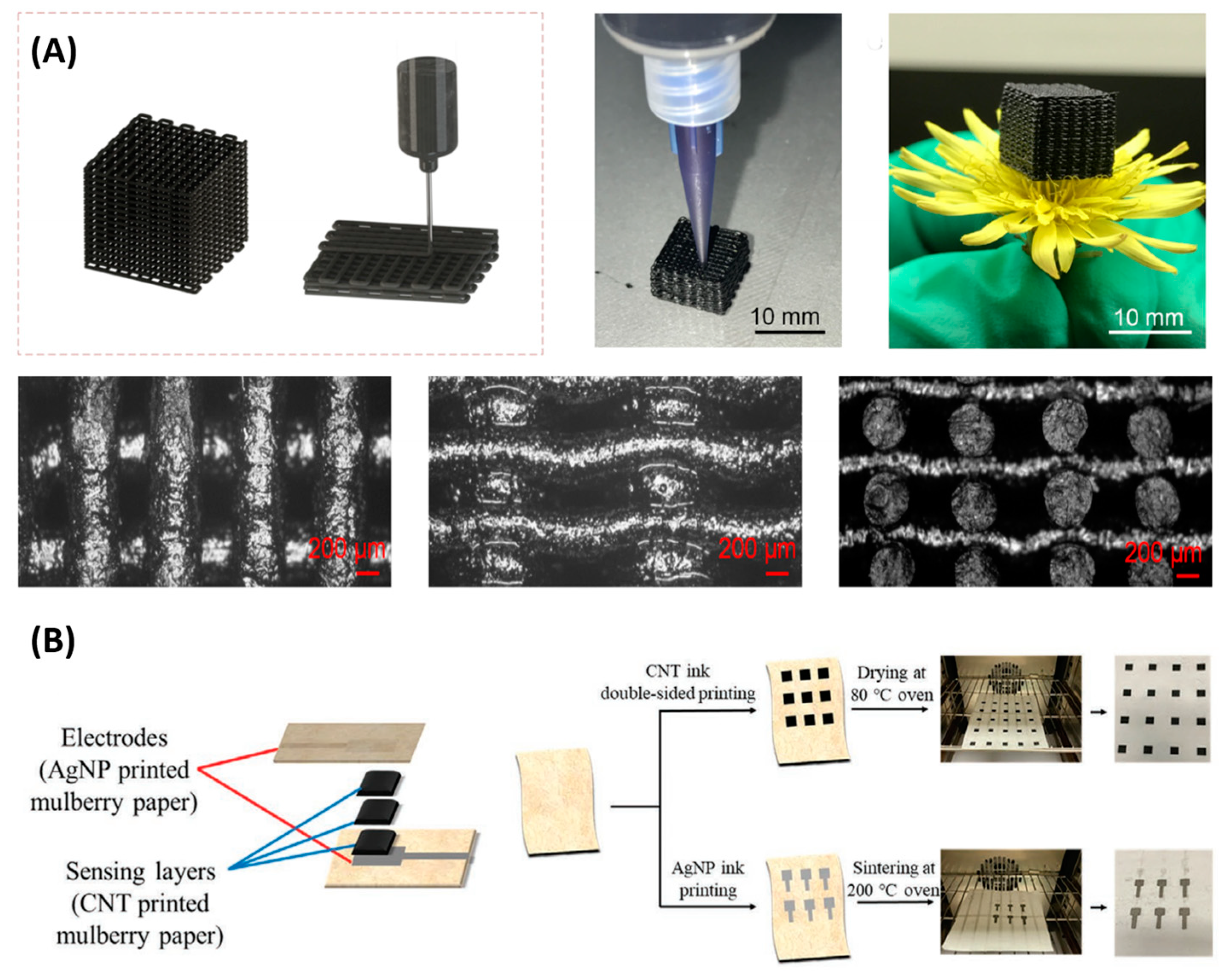
3.2.1. Printing

Roll-to-roll printing, screen printing, and inkjet printing are common printing methods for piezoresistive sensors. Roll-to-roll printing and screen printing are only suitable for 2D patterns, while inkjet printing is more versatile and maskless.
In inkjet printing, proper ink is prepared and directly printed on the receiver, forming a 2D or 3D structure. Inkjet 3D printing technology is also called direct ink writing, which is a layer-by-layer printing technique based on the pressure-driven deposition of ink through a nozzle [86,87]. Compared with other additive manufacturing technology, ink writing offers more diversity in the choice of materials. There is an ongoing appearance of novel materials for direct ink writing, e.g., polymers, metal, composites, etc. A review is presented in [87]. Inkjet printing is an attractive fabrication technique for flexible and thin film devices at a low cost. Both the sensing material and electronics can be fabricated by inkjet printing. For piezoresistive material, carbon-based nanomaterials such as CNTs are often added to the polymer to form composite ink with good electrical properties. For example, Tang et al. reported a soft and porous piezoresistive composite by 3D printing (Figure 5A). The ink was formed by dispersing CNTs and silica nanoparticles in a silicone elastomer solution [52]. Using 2D inkjet printing, Lee et al. developed an all-paper pressure sensor [88], as in Figure 5B. The carbon nanotubes were diluted in water, and printed on both sides of the stacked mulberry paper as sensing elements, followed by the drying process. Silver nanoparticles were printed as electrodes. The sensor exhibits a sensitivity exceeding 1 kPa−1 over a wide pressure range of 0.05~900 kPa.
Electronic components can also be fabricated by inkjet printing. Besides printed electrodes [88], printed thin film transistor (TFT) technology has been making progress in materials and methodology [89]. TFTs are promising for the integration of active pressure sensing arrays with low crosstalk and high flexibility. Using inkjet printing, Baek et al. fabricated 10 × 10 TFT arrays with various resolutions (up to 10.6 pixels per inch), achieving high uniformity (less than 10% relative standard deviation) and 100% yield. The electrodes are inkjet-printed using Ag nanoparticle ink, and perylene was deposited as the gate dielectric layer. Hydrophobic Teflon was printed as a bank line, and organic semiconductor ink was printed to fill the bank area. The TFT array was further integrated with piezoresistive sheets in a one-transistor-one-resistor structure, forming a wearable pressure sensor matrix [5].

3.2.2. Field-Assisted Processing

For solution-based fabrication, simple dip-coating or casting cannot guarantee a controlled positioning and alignment of the nanostructure and fillers inside the material. Electric fields and magnetic fields can be involved in the fabrication process for better manipulation.
There are multiple manufacturing technologies based on the electric field, including electrospinning, electroplating (aka., electrodeposition), electrospraying, etc. Among them, electrospinning is a mature and fast method for nanofiber production and alignment, which can be applied to produce flexible piezoresistive materials, as shown in Figure 6A,B. During electrospinning, high voltage was applied to the syringe, forming a Taylor cone. The charged threads were drawn from the syringe towards the grounded collector by the electric force, thus producing the nanofiber [90]. Conventional electrospinning is mostly used to generate 2D thin film mesh structure. For example, Li et al. fabricated a flexible piezoresistive sensor based on thermoplastic-urethane (TPU) decorated with carboxyl MWCNTs (c-MWCNTs), forming an electrospun fibrous network (~0.15 mm thickness) with good conductivity. The material has a sensitivity of 2 kPa−1, in the 10 kPa pressure range, and a hysteresis below 6% [39]. Electrospinning for 3D porous structures has also attracted attention. Han et al. applied electrospinning and thermal carbonization to fabricate a 3D porous carbon nanofiber network as a piezoresistive sensor in a simple and low-cost way [91] (Figure 6A). They prepared a precursor solution composed of polyacrylonitrile, dimethylformamide, and AlCl3. After electrospinning, the floc was preoxidized and then carbonized into the final porous carbon nanofiber networks. The material had a sensitivity of 1.41 kPa−1, stable resilience, and high compressibility. Kweon et al. fabricated PVDF-HFP/PEDOT nanofibers by 3D electrospinning and vapor deposition polymerization [49] (Figure 6B). The material had a sensitivity of 13.5 kPa−1 and a thickness of ~1 mm. It was further integrated into a 16 × 10 array in an 8 cm × 6 cm area for spatiotemporal pressure mapping.
The magnetic field can also assist in the alignment of fillers in composite solutions, as shown in Figure 6C,D. Composite piezoresistive materials with good properties can be achieved after magnetic field treatment. The advantage of the magnetic field is that it is cheap and easy to generate, e.g., just by permanent magnets. However, limited materials have a response to it, e.g., nickel, iron, carbon nanotubes, etc. For example, Kim et al. applied a magnetic field to align the nickel particles filled in the PDMS matrix prior to the curing process, forming an anisotropic percolation path that reduced the crosstalk. A piezoresistive film sensor with a spatial resolution of up to 100 dpi was fabricated with the material [26] (Figure 6C). Wang et al. applied a magnetic field to align the direction of magnetic rGO@nickel nanowires in the EcoFlex matrix during curing, resulting in a low percolation threshold of 0.27% and transmittance of 71.8%. The microdome microstructure was further involved by a hot embossing template. The sensor exhibits a sensitivity of 1302.1 kPa−1 [92] (Figure 6D).
Figure 6. (A) An example of electric field-assisted processing from [91]. (B) An example of electric field-assisted processing from [49]. (C) An example of magnetic field-assisted processing from [26]. Reproduced with permission from [26]. Copyright 2022, American Chemical Society. (D) An Example of magnetic field-assisted processing from [92]. Reproduced with permission from [92]. Copyright 2019, American Chemical Society.
Polymers 15 02699 g006

3.2.3. Laser-Assisted Processing

Laser is widely applied in today’s manufacturing. With different material properties and light parameters, the laser can induce different effects in the material, e.g., heating, ablation, carbonization, polymerization, etc.
Carbonaceous piezoresistive material can be generated from a polymeric precursor by laser irradiation. A typical example is laser-induced graphene (LIG), aka., laser-scribed graphene (LSG) [93,94]. One of the most popular precursors is polyimide, and the laser can be, e.g., infrared (IR) laser [95] or ultraviolet (UV) laser [25]. The property of the induced graphene material depends on the laser parameters, and its morphology is characterized by a porous pattern. The geometry of the sensor can be shaped by laser manufacturing. Laser cutting and Laser engraving are mature fabrication strategies. Laser cutting uses a high-power laser to cut through the material to form various shapes [25,50]. Laser engraving partially removes the material, fabricating controllable surface microstructure as templates [58]. Conventional silicon-based lithography and etching can also be applied to produce molds with precise morphologies; however, the devices are more expensive [57,96]. The following is representative of recent work using lasers for material fabrication and geometry. Li et al. used a UV laser to fabricate a serpentine piezoresistive array in two steps (Figure 7). In the first step, polyimide film was partially converted to isolated 3D porous graphene pixels by low-power UV laser (2.1~3.8 W). In the second step, higher laser power (6.8 W) was applied to cut the substrate layer by ablation to form the serpentine connection. Finally, an 8 × 8 array was created with a pixel size of 0.4 mm and a pixel distance of 0.3 mm [25].

4. Applications

4.1. Human-Interactive System

Human–computer interaction (HCI) is central to realizing efficient collaboration between humans and the digital world, and the data acquisition part of HCI inevitably relies heavily on pressure input [97]. Traditional input devices are less conformable and portable, e.g., keyboard, gamepad, and mouse. With the increasing requirements for acquisition accuracy, portability, and seamless interaction, flexible piezoresistive sensor arrays have more advantages in monitoring human movement, providing more possibilities for a new generation of human–computer interaction. In this section, we will introduce touchpads and tactile gloves, covering both control input devices and interactive systems.
Electronic skin patches and multipixel touchpads based on flexible sensor arrays are becoming a mainstream trend in HCI research [98]. They have the advantages of high sensitivity, compact size, good stability, and a relatively simple manufacturing process. Here, we introduce tactile keyboards and smart touchpads. To build a tactile keyboard, Pyo et al. introduced a tactile sensor comprising stacked carbon nanotubes and Ni-fabrics (Figure 8A) [99]. Flexible electronics based on multifunctional fabrics have attracted great interest for their light weight, flexibility, and easy fabrication [100]. The hierarchical structure of the fabric increases the contact area and distributes the stress to each layer of the fabric, improving sensitivity and linearity. The sensor presents a sensitivity of 26.13 kPa−1 over a pressure range of 0.2~982 kPa. The sensors were used to build a full-size all-fabric keyboard which included 29 tactile sensor cells corresponding to all 26 letter keys, a comma, a dot, and a space bar (Figure 8A). The sensor array consisted of 14 electrical lines constructed by the row-column selection wiring method. Smart touchpads can also be applied for more complex input recognition, such as handwritten digits and characters. Using a tactile sensor with 64 × 64 pixels, Zhao et al. collected 3099 images of handwritten digits, realizing a classification accuracy of 98.8% for testing. More complex Chinese characters were also collected. They selected 9 Chinese characters and collected a dataset of 900 images (100 for each). Different percentages of the handwritten data set were added to the computer-generated training set (12,150 images), and the recognition accuracy reached 97.3% (Figure 8B) [36].
Smart tactile gloves have become one of the most concerning branches of human–computer interaction. With human hands performing most of the tasks in everyday work, projecting hand movements and using them to control robots or virtual objects has become key to achieving immersive experiences in work, play, and learning. Currently, the relatively mature technology in smart gloves is the use of inertial measurement units (IMU) to measure hand movement. This kind of glove offers excellent accuracy and repeatability of angular motion tracking of fingers owing to the advanced MEMS technology [101]. However, purely IMU-based gloves lack applied force monitoring, especially when looking for information about touch. Therefore, piezoresistive material-based sensors have become an important supplement for smart glove sensing. By assembling flexible piezoresistive arrays, pressure distribution patterns during object grasping and manipulation can be studied, revealing how humans interact with the environment. Sinha et al. attached piezoresistive arrays on fingertips to form a smart glove that had 45 sensing points (3 × 3 array on each of the five fingers) to collect pressure information. Deep learning was used to identify sharp and blunt objects and the direction of the pressure with a classification accuracy of 95.9% and 97.8%, respectively [77] (Figure 9A). Charalambides et al. developed a glove capable of detecting both normal and shear forces, as shown in (Figure 9B) [102]. Each node of the sensor consisted of pillar and pad structures using CNT and PDMS. Different loading forces caused different contact statuses between the pillar and pad, which caused different contact resistances. Developing wearable smart gloves and ensuring their functionality require sensors to be robust to common forms of human hand movement, including large deformations and exposure to complex environments. Gao et al. reported a microfluidic tactile diaphragm pressure sensor based on embedded Galinstan microchannels (Figure 9C) [103]. Four sets of pressure sensors, including two tangential and two radial sensors, were connected end-to-end to form an equivalent Wheatstone bridge, providing highly sensitive output and temperature self-compensation. The proposed tactile sensor had a sensitivity of 0.0835 kPa−1 and a limit of detection of 100 Pa with sub-50 Pa resolution. Smart glove based on this sensor was capable of providing dynamic responses toward a variety of hand motions such as holding, gripping, grasping, squeezing, lifting, moving, or touching objects. Aiming to learn the full-hand tactile information of human grasping, Sundaram et al. fabricated a tactile glove with 548 sensing points covering the full hand. The glove was fabricated by attaching piezoresistive film (commercial conductive polymer, 3M Velostat) on the knitted glove, forming a passive matrix by arranging orthogonal electrodes. Using this tactile glove, they studied spatial and temporal tactile information when manipulating 26 objects and recorded a large-scale dataset with 135,000 frames. By training a deep convolutional neural network, typical tactile patterns of grasping motions were analyzed; object identification and weighing are demonstrated [4] (Figure 9D).
Further, combining tactile perception with remote feedback can be used to build remote sensing systems. The system usually includes a sensor at the remote end, a communication device for haptic data feedback, and an actuator as stimuli at the user end. For example, in Figure 9E, researchers developed a tactile interface consisting of the tactile glove, a linear-actuator-based tactile display, and two microcontroller units (MCUs) for data processing and wireless Bluetooth communication. The tactile information sensed by user A was measured by the wearable tactile glove, while simultaneously, the actuator-based tactile display provided tactile information to user B [99]. The construction can also be built into a teleoperation system [104,105], which is the user-side control of a robot in a remote scene to perform tasks, such as the manipulation of objects, which has great potential for various applications, e.g., telerobotic surgery and virtual reality. The tactile feedback is crucial for the planning of the movement and controlling of applied force.
Since arrayed sensors increase spatial information, more information about the contact can be explored. For the extraction of information from a large amount of pressure data, the rapid development of machine learning provides an effective way [106]. By utilizing appropriate learning models for specific sensing applications, more comprehensive information can be extracted for sensors that are simply designed, such as motion sequences, touch forces, and slides [107,108]. Based on training, the output patterns of grasping or touching behaviors of different objects, gestures and object recognition can be realized instead of simple motion detection at the primary level [109,110]. This will further build a more intelligent human-interactive system. In addition, machine learning algorithms can be carried out not only by computers after collecting the data but also in artificial-intelligent hardware for near-sensor computing. Memristor has been widely studied for building neuromorphic devices. A prototype implementation of the memristor-based compute-in-memory chip with a tactile sensor array is demonstrated in [36].
Figure 9. Glove-based human–machine interfaces: (A) Tactile glove with piezoresistive arrays on fingertips. Reproduced with permission from [77]. Copyright 2022, John Wiley and Sons. (B) Tactile glove capable of detecting both normal and shear forces. Reproduced with permission from [102]. Copyright 2016, John Wiley and Sons. (C) A microfluidic tactile diaphragm pressure sensor-based tactile glove capable of providing dynamic responses toward a variety of hand motions. Reproduced with permission from [103]. Copyright 2017, John Wiley and Sons. (D) Tactile glove for learning the full-hand tactile information of human grasping. Reproduced with permission from [4]. Copyright 2019, Springer Nature. (E) A tactile interface consists of the tactile glove, a linear-actuator-based tactile display, and two microcontroller units (MCUs) for data processing and wireless Bluetooth communication. Reproduced with permission from [99]. Copyright 2019, John Wiley and Sons.
Polymers 15 02699 g009

4.2. Healthcare

Pressure sensors can be applied in hospitals, where large datasets are easy to collect, thus, are promising for the application of machine learning algorithms to help automatic diagnosis. Plantar and pulse measurements are two main applications of the pressure sensor array in the medical field. Additionally, artificial skin based on sensor arrays is also often used in prosthetics to reconstruct the skin’s sensing response to the vital characteristic of external stimuli.
The measurement of plantar pressure distribution has a wide range of applications, including disease diagnosis, rehabilitation, athletic analysis, etc. For plantar pressure distribution measurement, typical requirements of the performance include (1) pressure range: over 1000 kPa in waking analysis, 1900 kPa in daily activities, and 3000 kPa in some extreme situations; (2) pressure resolution less than 10 kPa is widely accepted for insole, sometimes below 1 kPa (e.g., gait abnormality in diabetes); (3) bandwidth for dynamic pressure: 100 Hz for walking and 200 Hz for running and jumping; (4) a general element size of 5 mm is recommended by [111]. Considering the arrangement of sensor elements, there are two strategies. One is to measure the pressure distribution across the whole plantar area, and the other is placing sensing elements at several feature points. Several mature commercial products have been developed with the former strategy, e.g., the F-scan system by the Tekscan company (Figure 10A). Although these products provide sufficient information and are versatile, they have high costs, and the high density may be redundant. Related to this issue, many research works focus on developing new high-performance materials and arranging them at feature positions to demonstrate their usability for actual plantar measurement. Gait patterns are further extracted from the pressure distribution and analyzed by algorithms (e.g., machine learning) for diagnosis. For example, Xiao et al. fabricated polyvinylchloride/carbon black microgrid films for wearable applications. The sensor has a sensitivity of 4.71 kPa−1 in the working range of up to 15 kPa and a response time of 5 ms. An insole pressure sensing array with 24 units was realized. Three kinds of feet (normal foot, high arch foot, and flatfoot) and three walking gait phases (heel striking, standing, and pushing-off) can be identified [112] (Figure 10B). Monitoring plantar pressure is also helpful for patients with neural diseases that cause peripheral neuropathy or abnormal gait, e.g., diabetes [113], Parkinson’s disease [114,115], etc.
Wrist pulse signals can detect multiple health information, e.g., heart rate, blood pressure, vascular function, etc. Wearable pressure sensors for wrist pulse detection are widely studied. Since the pulse is weak and short impulse signal, new materials developed for pulse monitoring target high sensitivity and fast response. Noting that higher sensitivity may amplify both the target signal and the noise, it is also necessary to take signal-noise ratio (SNR) into evaluation when optimizing the sensor sensitivity (e.g., adjusting the filler proportion). Considering the stability and reliability of pulse monitoring, sensors with moderate sensitivity instead of ultrahigh sensitivity, are preferable [116]. Previous sensors are mostly individual sensor measurements, e.g., across the artery or specific positions according to traditional Chinese medicine [19]. Although exhibiting high performance, the optimal sensor position needs to be carefully determined due to the thin diameter of the radial artery. Compared with a single sensor, arrayed pressure sensors can better locate the arterial line and obtain a higher-quality signal for the assessment. Huang et al. proposed a linearly arranged 8 × 1 piezoresistive array for blood pulse monitoring above a radial artery. For each element, the length-width ratio is above eight and aligned along the artery direction for higher sensitivity. The sensor was fabricated by combining two layers of CNT/PDMS composites with interlock microdomes, exhibiting a sensitivity of −6.08 kPa−1 (Figure 10C) [117]. A 2D matrix has also been proposed. Baek et al. generated a spatial-temporal map of the pulse by integrating customizable thin film transistor arrays with piezoresistive film. It had a pressure sensitivity of 16.8 kPa−1 in the range of less than 1 kPa, 1.25 kPa−1 in the range of more than 2 kPa, and low power consumption of 10 nW. To monitor the cardiac condition, they observed the signals of each pixel in a 5 × 5 matrix to locate the artery line and extracted the augmentation index, which was an indicator of arterial stiffness (Figure 10D) [5].
Artificial skin constructed from piezoresistive sensor arrays can mimic many of the mechanical properties of human skin and realize a skin-like sensation, which provides several key advantages in helping amputees adapt to the use of prostheses and avoid injury [118].For example, providing sensory feedback from the prosthesis can make users more inclined to feel that the prosthesis is part of the body, promoting a sense of ownership [119]; stimulating the residual sensory pathways with sensory information can reduce phantom limb pain of up to 80% amputees [120]; providing tactile feedback can also make the operation of the prosthesis more natural and easier for patients [121,122]. Ferreira et al. developed a polymer-based piezoresistive sensor array that can assess the pressure distribution at the Interface of prosthetic alveolar in real-time. The sensor arrays enabled practitioners to better evaluate the matching degree of the socket and improve the performances of prosthetic alignment and training with a comfortable feeling for the patients (Figure 10E) [123]. Tactile feedback is important for the functional improvement of the prosthesis, Kim et al. [124] developed an artificial afferent nerve based on multiple piezoresistive sensors, realizing the connection to biological efferent nerves and demonstrating the information flow to actuate the tibial extensor muscle in the leg (Figure 10F). Osborn et al. [125] proposed a multi-layered, sensorized synthetic skin for prosthesis applications, which can provide a full map of tactile information feedback for the limb.
Figure 10. Healthcare applications: (A) F-scan system for plantar pressure measurement by the Tekscan company. (B) Plantar application of piezoresistive array to identify three kinds of feet (normal foot, high arch foot, and flatfoot) and three walking gait phases (heel striking, standing, and pushing-off). Reproduced with permission from [112]. Copyright 2019, IOP Publishing. (C) A linearly arranged 8 × 1 piezoresistive array for blood pulse monitoring above a radial artery. Reproduced with permission from [117]. Copyright 2018, Elsevier. (D) A 5 × 5 matrix for generating a spatial-temporal map of the pulse by integrating customizable thin film transistor arrays with piezoresistive film. Reproduced with permission from [5]. Copyright 2022, American Chemical Society. (E) Piezoresistive polymer-based sensors for assessing pressure distribution at the prosthetic interface. Reproduced with permission from [123]. Copyright 2017, IEEE. (F) An artificial afferent nerve based on multiple piezoresistive sensors. Reproduced with permission from [124]. Copyright 2018, Science.
Polymers 15 02699 g010

4.3. Others

The measurement of pressure distribution also has applications in underwater conditions, for example, in the marine environment. Marine biologging has been studied. By attaching sensors to marine animals, their behaviors and marine environment can be explored [126]. Bulky and rigid sensors may influence animal behavior; thus, a conformable and lightweight sensor is required. Moreover, the arrayed sensor can provide more detailed water conditions. Flexible pressure sensor arrays are promising for marine biologging. Nassar et al. proposed a fully conformable multi-sensing “marine skin” with a resistive type temperature sensor array and capacitive type pressure sensor array, which is 55 mm × 55 mm × 0.3 mm in size and weight less than 2.4 g (Figure 11A) [127]. Similar to the thin-film and flexible properties and better tolerance to humidity, piezoresistive sensor arrays could be promising for marine biologging. Besides biology and ecology, flow monitoring can also be applied to marine vehicles. In the water environment, the interaction between the hull and the water will affect the travel and maneuvering of the ship. Inspired by fish, real-time monitoring and feedback of the pressure distribution along the lateral line can assist marine vehicles in traveling better. Dusek et al. developed a four-by-one piezoresistive array in an 80 cm × 20 cm area for the pressure monitoring of unmanned marine vehicles with low-cost and waterproof (Figure 11B). They used carbon black-PDMS foam as the sensing material, with filler concentration near the percolation threshold. For underwater characterization, the sensor was attached to an automatic control platform which generated oscillation to create dynamic pressure. The signal was amplified and filtered by a 112.88 Hz low pass filter. Experiments showed that the sensor had a dynamic range of 50~500 Pa and a pressure resolution of 5 Pa [128].

5. Conclusions and Outlooks

In conclusion, this review comprehensively summarizes the considerations for developing flexible piezoresistive array devices, from the material and microstructure for performance enhancement to the array design and fabrication strategies, providing recent advances. The significance and application methods of flexible piezoresistive array devices to practical scenarios are also reviewed, providing ideas for more integrated sensing systems. Some typical and promising examples of piezoresistive array configurations in recent years and their performances are presented in Table 1. Array structures are classified into two categories. One is arranging discrete piezoresistive material elements in space, with each material element as a sensing pixel. The other is applying a continuous piece of piezoresistive material, with the intersection of electrodes as a sensing pixel. The material, microstructure, and corresponding performances of these typical researches are listed.
Future efforts can focus on the following aspects. First, improving the performance of flexible piezoresistive material is a constant issue, especially the unignorable problem of hysteresis that influences the accuracy of dynamic measurement; however, the amount of research work is limited. Future works should focus more on theories about hysteresis and develop adaptable materials with lower hysteresis. Second, polymer composites that are commonly used in flexible piezoresistive arrays exhibit poor selectivity under environmental interference, especially temperature [130,131]. The intrinsic reason is that the thermal expansion coefficient of the polymer matrix is usually higher than that of the filler, which leads to a mismatch in the thermal expansion between the two materials, causing internal variation when temperature changes. This is a vital problem for practical applications where pressure sensors may be required all year round or in extreme conditions. Third, although many high-performance new materials have only been made into single-point devices in research, they have the potential to be developed into high-performance array sensors through structural design methods mentioned in Section 3.1.2, which can further endow them with more versatility. Fourth, although the property of flexibility allows the sensors to be attached on a curved surface, pre-stress and pre-strain caused by the attachment surface may lead to the drift of resistance and degradation of electronic components (e.g., transistors). Fifth, the improvement of spatial resolution is constrained by crosstalk issues. While increasing the array density, attentions need to be paid to whether more significant crosstalk is introduced between adjacent pixels. Sixth, although materials with novel microstructure designs exhibit higher performance, uniformity and controllability are essential considerations for large-area and mass production. In terms of fabrication, efforts are still needed from laboratory production to industrial manufacturing, where the emphasis is on cost and time efficiency. Finally, in terms of application, most researches focus on robotics and wearable healthcare scenarios; however, pressure sensor arrays can assist in multiple scenarios where single-point pressure sensors are required. Despite the lack of precision and maturity, the relative spatial distribution can help extract new and complementary information.

Author Contributions

Conceptualization, H.L., Y.Y. and T.R.; methodology, S.X., Z.X., D.L., T.C. and X.L.; software, S.X., Z.X. and X.L.; validation, X.L., D.L. and T.C.; resources, S.X., Z.X. and D.L.; writing—original draft preparation, S.X. and Z.X.; writing—review and editing, H.L., D.L., X.L., T.C. and T.R.; visualization, S.X.; supervision, T.R.; project administration, H.L., Y.Y. and T.R.; funding acquisition, H.L., Y.Y. and T.R. All authors have read and agreed to the published version of the manuscript.

Funding

This work was supported by the National Key R&D Program (2022YFB3204100, 2021YFC3002200, 2020YFA0709800), the National Natural Science Foundation (U20A20168, 51861145202, 61874065) of China, Center for Flexible Electronics Technology of Tsinghua University, and a grant from the Guoqiang Institute, Tsinghua University.

Institutional Review Board Statement

Not applicable.

Informed Consent Statement

Not applicable.

Data Availability Statement

Not applicable.

Conflicts of Interest

The authors declare no conflict of interest.

References

  1. Oh, H.; Yi, G.-C.; Yip, M.; Dayeh, S.A. Scalable Tactile Sensor Arrays on Flexible Substrates with High Spatiotemporal Resolution Enabling Slip and Grip for Closed-Loop Robotics. Sci. Adv. 2020, 6, eabd7795. [Google Scholar] [CrossRef]
  2. Qu, X.; Liu, Z.; Tan, P.; Wang, C.; Liu, Y.; Feng, H.; Luo, D.; Li, Z.; Wang, Z.L. Artificial Tactile Perception Smart Finger for Material Identification Based on Triboelectric Sensing. Sci. Adv. 2022, 8, eabq2521. [Google Scholar] [CrossRef] [PubMed]
  3. Yin, R.; Wang, D.; Zhao, S.; Lou, Z.; Shen, G. Wearable Sensors-Enabled Human–Machine Interaction Systems: From Design to Application. Adv. Funct. Mater. 2021, 31, 2008936. [Google Scholar] [CrossRef]
  4. Sundaram, S.; Kellnhofer, P.; Li, Y.; Zhu, J.-Y.; Torralba, A.; Matusik, W. Learning the Signatures of the Human Grasp Using a Scalable Tactile Glove. Nature 2019, 569, 698–702. [Google Scholar] [CrossRef]
  5. Baek, S.; Lee, Y.; Baek, J.; Kwon, J.; Kim, S.; Lee, S.; Strunk, K.-P.; Stehlin, S.; Melzer, C.; Park, S.-M.; et al. Spatiotemporal Measurement of Arterial Pulse Waves Enabled by Wearable Active-Matrix Pressure Sensor Arrays. ACS Nano 2022, 16, 368–377. [Google Scholar] [CrossRef]
  6. Chen, J.; Dai, Y.; Grimaldi, N.S.; Lin, J.; Hu, B.; Wu, Y.; Gao, S. Plantar Pressure-Based Insole Gait Monitoring Techniques for Diseases Monitoring and Analysis: A Review. Adv. Mater. Technol. 2022, 7, 2100566. [Google Scholar] [CrossRef]
  7. Fiorillo, A.S.; Critello, C.D.; Pullano, S.A. Theory, Technology and Applications of Piezoresistive Sensors: A Review. Sens. Actuators A Phys. 2018, 281, 156–175. [Google Scholar] [CrossRef]
  8. Li, G.; Chen, D.; Li, C.; Liu, W.; Liu, H. Engineered Microstructure Derived Hierarchical Deformation of Flexible Pressure Sensor Induces a Supersensitive Piezoresistive Property in Broad Pressure Range. Adv. Sci. 2020, 7, 2000154. [Google Scholar] [CrossRef]
  9. Mishra, R.B.; El-Atab, N.; Hussain, A.M.; Hussain, M.M. Recent Progress on Flexible Capacitive Pressure Sensors: From Design and Materials to Applications. Adv. Mater. Technol. 2021, 6, 2001023. [Google Scholar] [CrossRef]
  10. Pyo, S.; Choi, J.; Kim, J. Flexible, Transparent, Sensitive, and Crosstalk-Free Capacitive Tactile Sensor Array Based on Graphene Electrodes and Air Dielectric. Adv. Electron. Mater. 2018, 4, 1700427. [Google Scholar] [CrossRef]
  11. Lin, W.; Wang, B.; Peng, G.; Shan, Y.; Hu, H.; Yang, Z. Skin-Inspired Piezoelectric Tactile Sensor Array with Crosstalk-Free Row + Column Electrodes for Spatiotemporally Distinguishing Diverse Stimuli. Adv. Sci. 2021, 8, 2002817. [Google Scholar] [CrossRef] [PubMed]
  12. Wang, J.; Jiang, J.; Zhang, C.; Sun, M.; Han, S.; Zhang, R.; Liang, N.; Sun, D.; Liu, H. Energy-Efficient, Fully Flexible, High-Performance Tactile Sensor Based on Piezotronic Effect: Piezoelectric Signal Amplified with Organic Field-Effect Transistors. Nano Energy 2020, 76, 105050. [Google Scholar] [CrossRef]
  13. Tao, J.; Bao, R.; Wang, X.; Peng, Y.; Li, J.; Fu, S.; Pan, C.; Wang, Z.L. Self-Powered Tactile Sensor Array Systems Based on the Triboelectric Effect. Adv. Funct. Mater. 2019, 29, 1806379. [Google Scholar] [CrossRef]
  14. He, J.; Xie, Z.; Yao, K.; Li, D.; Liu, Y.; Gao, Z.; Lu, W.; Chang, L.; Yu, X. Trampoline Inspired Stretchable Triboelectric Nanogenerators as Tactile Sensors for Epidermal Electronics. Nano Energy 2021, 81, 105590. [Google Scholar] [CrossRef]
  15. Huang, Y.; Fan, X.; Chen, S.; Zhao, N. Emerging Technologies of Flexible Pressure Sensors: Materials, Modeling, Devices, and Manufacturing. Adv. Funct. Mater. 2019, 29, 1808509. [Google Scholar] [CrossRef]
  16. Oh, J.; Kim, J.; Kim, Y.; Choi, H.B.; Yang, J.C.; Lee, S.; Pyatykh, M.; Kim, J.; Sim, J.Y.; Park, S. Highly Uniform and Low Hysteresis Piezoresistive Pressure Sensors Based on Chemical Grafting of Polypyrrole on Elastomer Template with Uniform Pore Size. Small 2019, 15, 1901744. [Google Scholar] [CrossRef]
  17. Park, K.; Kim, S.; Lee, H.; Park, I.; Kim, J. Low-Hysteresis and Low-Interference Soft Tactile Sensor Using a Conductive Coated Porous Elastomer and a Structure for Interference Reduction. Sens. Actuators A Phys. 2019, 295, 541–550. [Google Scholar] [CrossRef]
  18. Chang, S.; Li, J.; He, Y.; Liu, H.; Cheng, B. A High-Sensitivity and Low-Hysteresis Flexible Pressure Sensor Based on Carbonized Cotton Fabric. Sens. Actuators A Phys. 2019, 294, 45–53. [Google Scholar] [CrossRef]
  19. Chen, J.; Zhang, J.; Hu, J.; Luo, N.; Sun, F.; Venkatesan, H.; Zhao, N.; Zhang, Y. Ultrafast-Response/Recovery Flexible Piezoresistive Sensors with DNA-Like Double Helix Yarns for Epidermal Pulse Monitoring. Adv. Mater. 2022, 34, 2104313. [Google Scholar] [CrossRef]
  20. Klimm, W.; Kwok, K. Mechanism of Resistance Relaxation and Hysteresis in Viscoelastic Piezoresistive Polymer Nanocomposites. Int. J. Mech. Mater. Des. 2022, 18, 769–783. [Google Scholar] [CrossRef]
  21. Paredes-Madrid, L.; Fonseca, J.; Matute, A.; Gutiérrez Velásquez, E.; Palacio, C. Self-Compensated Driving Circuit for Reducing Drift and Hysteresis in Force Sensing Resistors. Electronics 2018, 7, 146. [Google Scholar] [CrossRef] [Green Version]
  22. Oliveri, A.; Maselli, M.; Lodi, M.; Storace, M.; Cianchetti, M. Model-Based Compensation of Rate-Dependent Hysteresis in a Piezoresistive Strain Sensor. IEEE Trans. Ind. Electron. 2019, 66, 8205–8213. [Google Scholar] [CrossRef]
  23. Pyo, S.; Lee, J.; Bae, K.; Sim, S.; Kim, J. Recent Progress in Flexible Tactile Sensors for Human-Interactive Systems: From Sensors to Advanced Applications. Adv. Mater. 2021, 33, 2005902. [Google Scholar] [CrossRef]
  24. Li, L.; Fu, X.; Chen, S.; Uzun, S.; Levitt, A.S.; Shuck, C.E.; Han, W.; Gogotsi, Y. Hydrophobic and Stable MXene–Polymer Pressure Sensors for Wearable Electronics. ACS Appl. Mater. Interfaces 2020, 12, 15362–15369. [Google Scholar] [CrossRef]
  25. Li, Y.; Long, J.; Chen, Y.; Huang, Y.; Zhao, N. Crosstalk-Free, High-Resolution Pressure Sensor Arrays Enabled by High-Throughput Laser Manufacturing. Adv. Mater. 2022, 34, 2200517. [Google Scholar] [CrossRef] [PubMed]
  26. Kim, H.; Choi, S.; Lee, B.; Seo, J.; Lee, S.; Yoon, J.; Hong, Y. Nonpatterned Soft Piezoresistive Films with Filamentous Conduction Paths for Mimicking Multiple-Resolution Receptors of Human Skin. ACS Appl. Mater. Interfaces 2022, 14, 55088–55097. [Google Scholar] [CrossRef]
  27. He, J.; Zhang, Y.; Zhou, R.; Meng, L.; Chen, T.; Mai, W.; Pan, C. Recent Advances of Wearable and Flexible Piezoresistivity Pressure Sensor Devices and Its Future Prospects. J. Mater. 2020, 6, 86–101. [Google Scholar] [CrossRef]
  28. Pierre Claver, U.; Zhao, G. Recent Progress in Flexible Pressure Sensors Based Electronic Skin. Adv. Eng. Mater. 2021, 23, 2001187. [Google Scholar] [CrossRef]
  29. He, F.; You, X.; Wang, W.; Bai, T.; Xue, G.; Ye, M. Recent Progress in Flexible Microstructural Pressure Sensors toward Human–Machine Interaction and Healthcare Applications. Small Methods 2021, 5, 2001041. [Google Scholar] [CrossRef]
  30. Bauhofer, W.; Kovacs, J.Z. A Review and Analysis of Electrical Percolation in Carbon Nanotube Polymer Composites. Compos. Sci. Technol. 2009, 69, 1486–1498. [Google Scholar] [CrossRef]
  31. Haghgoo, M.; Hassanzadeh-Aghdam, M.K.; Ansari, R. A Comprehensive Evaluation of Piezoresistive Response and Percolation Behavior of Multiscale Polymer-Based Nanocomposites. Compos. Part A Appl. Sci. Manuf. 2020, 130, 105735. [Google Scholar] [CrossRef]
  32. Long, Z.; Liu, X.; Xu, J.; Huang, Y.; Wang, Z. High-Sensitivity Flexible Piezoresistive Pressure Sensor Using PDMS/MWNTS Nanocomposite Membrane Reinforced with Isopropanol for Pulse Detection. Sensors 2022, 22, 4765. [Google Scholar] [CrossRef]
  33. Wang, L.; Peng, H.; Wang, X.; Chen, X.; Yang, C.; Yang, B.; Liu, J. PDMS/MWCNT-Based Tactile Sensor Array with Coplanar Electrodes for Crosstalk Suppression. Microsyst. Nanoeng. 2016, 2, 16065. [Google Scholar] [CrossRef] [Green Version]
  34. Zhang, S.; Liu, H.; Yang, S.; Shi, X.; Zhang, D.; Shan, C.; Mi, L.; Liu, C.; Shen, C.; Guo, Z. Ultrasensitive and Highly Compressible Piezoresistive Sensor Based on Polyurethane Sponge Coated with a Cracked Cellulose Nanofibril/Silver Nanowire Layer. ACS Appl. Mater. Interfaces 2019, 11, 10922–10932. [Google Scholar] [CrossRef]
  35. Zhai, Y.; Yu, Y.; Zhou, K.; Yun, Z.; Huang, W.; Liu, H.; Xia, Q.; Dai, K.; Zheng, G.; Liu, C.; et al. Flexible and Wearable Carbon Black/Thermoplastic Polyurethane Foam with a Pinnate-Veined Aligned Porous Structure for Multifunctional Piezoresistive Sensors. Chem. Eng. J. 2020, 382, 122985. [Google Scholar] [CrossRef]
  36. Zhao, Z.; Tang, J.; Yuan, J.; Li, Y.; Dai, Y.; Yao, J.; Zhang, Q.; Ding, S.; Li, T.; Zhang, R.; et al. Large-Scale Integrated Flexible Tactile Sensor Array for Sensitive Smart Robotic Touch. ACS Nano 2022, 16, 16784–16795. [Google Scholar] [CrossRef] [PubMed]
  37. Han, X.; Lv, Z.; Ran, F.; Dai, L.; Li, C.; Si, C. Green and Stable Piezoresistive Pressure Sensor Based on Lignin-Silver Hybrid Nanoparticles/Polyvinyl Alcohol Hydrogel. Int. J. Biol. Macromol. 2021, 176, 78–86. [Google Scholar] [CrossRef] [PubMed]
  38. Duan, L.; Spoerk, M.; Wieme, T.; Cornillie, P.; Xia, H.; Zhang, J.; Cardon, L.; D’hooge, D.R. Designing Formulation Variables of Extrusion-Based Manufacturing of Carbon Black Conductive Polymer Composites for Piezoresistive Sensing. Compos. Sci. Technol. 2019, 171, 78–85. [Google Scholar] [CrossRef]
  39. Li, S.; Li, R.; González, O.G.; Chen, T.; Xiao, X. Highly Sensitive and Flexible Piezoresistive Sensor Based on c-MWCNTs Decorated TPU Electrospun Fibrous Network for Human Motion Detection. Compos. Sci. Technol. 2021, 203, 108617. [Google Scholar] [CrossRef]
  40. Dai, H.; Thostenson, E.T. Large-Area Carbon Nanotube-Based Flexible Composites for Ultra-Wide Range Pressure Sensing and Spatial Pressure Mapping. ACS Appl. Mater. Interfaces 2019, 11, 48370–48380. [Google Scholar] [CrossRef]
  41. Chen, K.-Y.; Xu, Y.-T.; Zhao, Y.; Li, J.-K.; Wang, X.-P.; Qu, L.-T. Recent Progress in Graphene-Based Wearable Piezoresistive Sensors: From 1D to 3D Device Geometries. Nano Mater. Sci. 2022. [Google Scholar] [CrossRef]
  42. Pang, Y.; Zhang, K.; Yang, Z.; Jiang, S.; Ju, Z.; Li, Y.; Wang, X.; Wang, D.; Jian, M.; Zhang, Y.; et al. Epidermis Microstructure Inspired Graphene Pressure Sensor with Random Distributed Spinosum for High Sensitivity and Large Linearity. ACS Nano 2018, 12, 2346–2354. [Google Scholar] [CrossRef] [PubMed]
  43. Ke, K.; Yue, L.; Shao, H.; Yang, M.-B.; Yang, W.; Manas-Zloczower, I. Boosting Electrical and Piezoresistive Properties of Polymer Nanocomposites via Hybrid Carbon Fillers: A Review. Carbon 2021, 173, 1020–1040. [Google Scholar] [CrossRef]
  44. Zhu, B.; Ling, Y.; Yap, L.W.; Yang, M.; Lin, F.; Gong, S.; Wang, Y.; An, T.; Zhao, Y.; Cheng, W. Hierarchically Structured Vertical Gold Nanowire Array-Based Wearable Pressure Sensors for Wireless Health Monitoring. ACS Appl. Mater. Interfaces 2019, 11, 29014–29021. [Google Scholar] [CrossRef]
  45. Chen, B.; Zhang, L.; Li, H.; Lai, X.; Zeng, X. Skin-Inspired Flexible and High-Performance MXene@polydimethylsiloxane Piezoresistive Pressure Sensor for Human Motion Detection. J. Colloid Interface Sci. 2022, 617, 478–488. [Google Scholar] [CrossRef] [PubMed]
  46. Yan, J.; Ma, Y.; Jia, G.; Zhao, S.; Yue, Y.; Cheng, F.; Zhang, C.; Cao, M.; Xiong, Y.; Shen, P.; et al. Bionic MXene Based Hybrid Film Design for an Ultrasensitive Piezoresistive Pressure Sensor. Chem. Eng. J. 2022, 431, 133458. [Google Scholar] [CrossRef]
  47. Qin, Z.; Lv, Y.; Fang, X.; Zhao, B.; Niu, F.; Min, L.; Pan, K. Ultralight Polypyrrole Crosslinked Nanofiber Aerogel for Highly Sensitive Piezoresistive Sensor. Chem. Eng. J. 2022, 427, 131650. [Google Scholar] [CrossRef]
  48. Li, L.; Bao, X.; Meng, J.; Zhang, C.; Liu, T. Sponge-Hosting Polyaniline Array Microstructures for Piezoresistive Sensors with a Wide Detection Range and High Sensitivity. ACS Appl. Mater. Interfaces 2022, 14, 30228–30235. [Google Scholar] [CrossRef] [PubMed]
  49. Kweon, O.Y.; Lee, S.J.; Oh, J.H. Wearable High-Performance Pressure Sensors Based on Three-Dimensional Electrospun Conductive Nanofibers. NPG Asia Mater. 2018, 10, 540–551. [Google Scholar] [CrossRef] [Green Version]
  50. Han, M.; Chen, L.; Aras, K.; Liang, C.; Chen, X.; Zhao, H.; Li, K.; Faye, N.R.; Sun, B.; Kim, J.-H.; et al. Catheter-Integrated Soft Multilayer Electronic Arrays for Multiplexed Sensing and Actuation during Cardiac Surgery. Nat. Biomed. Eng. 2020, 4, 997–1009. [Google Scholar] [CrossRef]
  51. Shi, L.; Li, Z.; Chen, M.; Qin, Y.; Jiang, Y.; Wu, L. Quantum Effect-Based Flexible and Transparent Pressure Sensors with Ultrahigh Sensitivity and Sensing Density. Nat. Commun. 2020, 11, 3529. [Google Scholar] [CrossRef] [PubMed]
  52. Tang, Z.; Jia, S.; Zhou, C.; Li, B. 3D Printing of Highly Sensitive and Large-Measurement-Range Flexible Pressure Sensors with a Positive Piezoresistive Effect. ACS Appl. Mater. Interfaces 2020, 12, 28669–28680. [Google Scholar] [CrossRef] [PubMed]
  53. Gao, Y.; Lu, C.; Guohui, Y.; Sha, J.; Tan, J.; Xuan, F. Laser Micro-Structured Pressure Sensor with Modulated Sensitivity for Electronic Skins. Nanotechnology 2019, 30, 325502. [Google Scholar] [CrossRef] [PubMed]
  54. Li, H.; Wu, K.; Xu, Z.; Wang, Z.; Meng, Y.; Li, L. Ultrahigh-Sensitivity Piezoresistive Pressure Sensors for Detection of Tiny Pressure. ACS Appl. Mater. Interfaces 2018, 10, 20826–20834. [Google Scholar] [CrossRef] [PubMed]
  55. Park, J.; Kim, J.; Hong, J.; Lee, H.; Lee, Y.; Cho, S.; Kim, S.-W.; Kim, J.J.; Kim, S.Y.; Ko, H. Tailoring Force Sensitivity and Selectivity by Microstructure Engineering of Multidirectional Electronic Skins. NPG Asia Mater. 2018, 10, 163–176. [Google Scholar] [CrossRef] [Green Version]
  56. Chen, M.; Li, K.; Cheng, G.; He, K.; Li, W.; Zhang, D.; Li, W.; Feng, Y.; Wei, L.; Li, W.; et al. Touchpoint-Tailored Ultrasensitive Piezoresistive Pressure Sensors with a Broad Dynamic Response Range and Low Detection Limit. ACS Appl. Mater. Interfaces 2019, 11, 2551–2558. [Google Scholar] [CrossRef]
  57. Niu, H.; Zhang, H.; Yue, W.; Gao, S.; Kan, H.; Zhang, C.; Zhang, C.; Pang, J.; Lou, Z.; Wang, L.; et al. Micro-Nano Processing of Active Layers in Flexible Tactile Sensors via Template Methods: A Review. Small 2021, 17, 2100804. [Google Scholar] [CrossRef]
  58. dos Santos, A.; Pinela, N.; Alves, P.; Santos, R.; Fortunato, E.; Martins, R.; Águas, H.; Igreja, R. Piezoresistive E-Skin Sensors Produced with Laser Engraved Molds. Adv. Electron. Mater. 2018, 4, 1800182. [Google Scholar] [CrossRef]
  59. Yao, H.; Yang, W.; Cheng, W.; Tan, Y.J.; See, H.H.; Li, S.; Ali, H.P.A.; Lim, B.Z.H.; Liu, Z.; Tee, B.C.K. Near–Hysteresis-Free Soft Tactile Electronic Skins for Wearables and Reliable Machine Learning. Proc. Natl. Acad. Sci. USA 2020, 117, 25352–25359. [Google Scholar] [CrossRef]
  60. Du, D.; Ma, X.; An, W.; Yu, S. Flexible Piezoresistive Pressure Sensor Based on Wrinkled Layers with Fast Response for Wearable Applications. Measurement 2022, 201, 111645. [Google Scholar] [CrossRef]
  61. Charara, M.; Luo, W.; Saha, M.C.; Liu, Y. Investigation of Lightweight and Flexible Carbon Nanofiber/Poly Dimethylsiloxane Nanocomposite Sponge for Piezoresistive Sensor Application. Adv. Eng. Mater. 2019, 21, 1801068. [Google Scholar] [CrossRef]
  62. Dai, S.-W.; Gu, Y.-L.; Zhao, L.; Zhang, W.; Gao, C.-H.; Wu, Y.-X.; Shen, S.-C.; Zhang, C.; Kong, T.-T.; Li, Y.-T.; et al. Bamboo-Inspired Mechanically Flexible and Electrically Conductive Polydimethylsiloxane Foam Materials with Designed Hierarchical Pore Structures for Ultra-Sensitive and Reliable Piezoresistive Pressure Sensor. Compos. Part B. Eng. 2021, 225, 109243. [Google Scholar] [CrossRef]
  63. Li, W.; Jin, X.; Han, X.; Li, Y.; Wang, W.; Lin, T.; Zhu, Z. Synergy of Porous Structure and Microstructure in Piezoresistive Material for High-Performance and Flexible Pressure Sensors. ACS Appl. Mater. Interfaces 2021, 13, 19211–19220. [Google Scholar] [CrossRef] [PubMed]
  64. Yang, W.; Hon, M.; Yao, H.; Tee, B.C.K. An Atlas for Large-Area Electronic Skins: From Materials to Systems Design, 1st ed.; Cambridge University Press: Cambridge, UK, 2020; ISBN 978-1-108-78239-5. [Google Scholar]
  65. Takei, K.; Takahashi, T.; Ho, J.C.; Ko, H.; Gillies, A.G.; Leu, P.W.; Fearing, R.S.; Javey, A. Nanowire Active-Matrix Circuitry for Low-Voltage Macroscale Artificial Skin. Nature Mater. 2010, 9, 821–826. [Google Scholar] [CrossRef] [PubMed]
  66. Shi, J.; Wang, L.; Dai, Z.; Zhao, L.; Du, M.; Li, H.; Fang, Y. Multiscale Hierarchical Design of a Flexible Piezoresistive Pressure Sensor with High Sensitivity and Wide Linearity Range. Small 2018, 14, 1800819. [Google Scholar] [CrossRef] [PubMed]
  67. Li, X.; Li, X.; Liu, T.; Lu, Y.; Shang, C.; Ding, X.; Zhang, J.; Feng, Y.; Xu, F.-J. Wearable, Washable, and Highly Sensitive Piezoresistive Pressure Sensor Based on a 3D Sponge Network for Real-Time Monitoring Human Body Activities. ACS Appl. Mater. Interfaces 2021, 13, 46848–46857. [Google Scholar] [CrossRef]
  68. Liu, W.C.; Watt, A.A.R. Solvodynamically Printed Silver Nanowire/Ethylene-Co-Vinyl Acetate Composite Films as Sensitive Piezoresistive Pressure Sensors. ACS Appl. Nano Mater. 2021, 4, 7905–7916. [Google Scholar] [CrossRef]
  69. Kim, J.-S.; So, Y.; Lee, S.; Pang, C.; Park, W.; Chun, S. Uniform Pressure Responses for Nanomaterials-Based Biological on-Skin Flexible Pressure Sensor Array. Carbon 2021, 181, 169–176. [Google Scholar] [CrossRef]
  70. Pei, Z.; Zhang, Q.; Li, Q.; Ji, C.; Liu, Y.; Yang, K.; Zhuo, K.; Zhang, W.; Sang, S. A Fully 3D Printed Electronic Skin with Bionic High Resolution and Air Permeable Porous Structure. J. Colloid Interface Sci. 2021, 602, 452–458. [Google Scholar] [CrossRef]
  71. Fan, B.; Chen, S.; Gao, J.; Guo, X. Accurate Recognition of Lightweight Objects with Low Resolution Pressure Sensor Array. IEEE Sens. J. 2020, 20, 3280–3284. [Google Scholar] [CrossRef]
  72. Lee, B.; Oh, J.-Y.; Cho, H.; Joo, C.W.; Yoon, H.; Jeong, S.; Oh, E.; Byun, J.; Kim, H.; Lee, S.; et al. Ultraflexible and Transparent Electroluminescent Skin for Real-Time and Super-Resolution Imaging of Pressure Distribution. Nat. Commun. 2020, 11, 663. [Google Scholar] [CrossRef] [Green Version]
  73. Silvera-Tawil, D.; Rye, D.; Soleimani, M.; Velonaki, M. Electrical Impedance Tomography for Artificial Sensitive Robotic Skin: A Review. IEEE Sens. J. 2015, 15, 2001–2016. [Google Scholar] [CrossRef] [Green Version]
  74. Lee, H.; Kwon, D.; Cho, H.; Park, I.; Kim, J. Soft Nanocomposite Based Multi-Point, Multi-Directional Strain Mapping Sensor Using Anisotropic Electrical Impedance Tomography. Sci. Rep. 2017, 7, 39837. [Google Scholar] [CrossRef] [PubMed] [Green Version]
  75. Jeong, Y.J.; Kim, Y.E.; Kim, K.J.; Woo, E.J.; Oh, T.I. Multilayered Fabric Pressure Sensor for Real-Time Piezo-Impedance Imaging of Pressure Distribution. IEEE Trans. Instrum. Meas. 2020, 69, 565–572. [Google Scholar] [CrossRef]
  76. Liu, K.; Wu, Y.; Wang, S.; Wang, H.; Chen, H.; Chen, B.; Yao, J. Artificial Sensitive Skin for Robotics Based on Electrical Impedance Tomography. Adv. Intell. Syst. 2020, 2, 1900161. [Google Scholar] [CrossRef] [Green Version]
  77. Sinha, A.K.; Goh, G.L.; Yeong, W.Y.; Cai, Y. Ultra-Low-Cost, Crosstalk-Free, Fast-Responding, Wide-Sensing-Range Tactile Fingertip Sensor for Smart Gloves. Adv. Mater. Interfaces 2022, 9, 2200621. [Google Scholar] [CrossRef]
  78. Yin, Y.M.; Li, H.Y.; Xu, J.; Zhang, C.; Liang, F.; Li, X.; Jiang, Y.; Cao, J.W.; Feng, H.F.; Mao, J.N.; et al. Facile Fabrication of Flexible Pressure Sensor with Programmable Lattice Structure. ACS Appl. Mater. Interfaces 2021, 13, 10388–10396. [Google Scholar] [CrossRef]
  79. Bae, K.; Jeong, J.; Choi, J.; Pyo, S.; Kim, J. Large-Area, Crosstalk-Free, Flexible Tactile Sensor Matrix Pixelated by Mesh Layers. ACS Appl. Mater. Interfaces 2021, 13, 12259–12267. [Google Scholar] [CrossRef]
  80. Kim, J.-S.; Kwon, D.-Y.; Choi, B.-D. High-Accuracy, Compact Scanning Method and Circuit for Resistive Sensor Arrays. Sensors 2016, 16, 155. [Google Scholar] [CrossRef] [Green Version]
  81. Tanaka, A.; Matsumoto, S.; Tsukamoto, N.; Itoh, S.; Chiba, K.; Endoh, T.; Nakazato, A.; Okuyama, K.; Kumazawa, Y.; Hijikawa, M.; et al. Infrared Focal Plane Array Incorporating Silicon IC Process Compatible Bolometer. IEEE Trans. Electron. Devices 1996, 43, 1844–1850. [Google Scholar] [CrossRef]
  82. Tise, B. A Compact High Resolution Piezoresistive Digital Tactile Sensor. In Proceedings of the 1988 IEEE International Conference on Robotics and Automation, Philadelphia, PA, USA, 24–29 April 1988. [Google Scholar]
  83. Wu, J.; Wang, L.; Li, J. General Voltage Feedback Circuit Model in the Two-Dimensional Networked Resistive Sensor Array. J. Sens. 2015, 2015, 913828. [Google Scholar] [CrossRef] [Green Version]
  84. Vidal-Verdú, F.; Oballe-Peinado, Ó.; Sánchez-Durán, J.A.; Castellanos-Ramos, J.; Navas-González, R. Three Realizations and Comparison of Hardware for Piezoresistive Tactile Sensors. Sensors 2011, 11, 3249–3266. [Google Scholar] [CrossRef] [PubMed] [Green Version]
  85. Shu, L.; Tao, X.; Feng, D.D. A New Approach for Readout of Resistive Sensor Arrays for Wearable Electronic Applications. IEEE Sens. J. 2015, 15, 442–452. [Google Scholar] [CrossRef]
  86. Shah, M.A.; Lee, D.-G.; Lee, B.-Y.; Hur, S. Classifications and Applications of Inkjet Printing Technology: A Review. IEEE Access 2021, 9, 140079–140102. [Google Scholar] [CrossRef]
  87. Saadi, M.A.S.R.; Maguire, A.; Pottackal, N.T.; Thakur, M.S.H.; Ikram, M.M.; Hart, A.J.; Ajayan, P.M.; Rahman, M.M. Direct Ink Writing: A 3D Printing Technology for Diverse Materials. Adv. Mater. 2022, 34, 2108855. [Google Scholar] [CrossRef]
  88. Lee, T.; Kang, Y.; Kim, K.; Sim, S.; Bae, K.; Kwak, Y.; Park, W.; Kim, M.; Kim, J. All Paper-Based, Multilayered, Inkjet-Printed Tactile Sensor in Wide Pressure Detection Range with High Sensitivity. Adv. Mater. Technol. 2022, 7, 2100428. [Google Scholar] [CrossRef]
  89. Chung, S.; Cho, K.; Lee, T. Recent Progress in Inkjet-Printed Thin-Film Transistors. Adv. Sci. 2019, 6, 1801445. [Google Scholar] [CrossRef]
  90. Theron, A.; Zussman, E.; Yarin, A.L. Electrostatic Field-Assisted Alignment of Electrospun Nanofibres. Nanotechnology 2001, 12, 384–390. [Google Scholar] [CrossRef]
  91. Han, Z.; Cheng, Z.; Chen, Y.; Li, B.; Liang, Z.; Li, H.; Ma, Y.; Feng, X. Fabrication of Highly Pressure-Sensitive, Hydrophobic, and Flexible 3D Carbon Nanofiber Networks by Electrospinning for Human Physiological Signal Monitoring. Nanoscale 2019, 11, 5942–5950. [Google Scholar] [CrossRef] [Green Version]
  92. Wang, S.; Chen, G.; Niu, S.; Chen, K.; Gan, T.; Wang, Z.; Wang, H.; Du, P.; Leung, C.W.; Qu, S. Magnetic-Assisted Transparent and Flexible Percolative Composite for Highly Sensitive Piezoresistive Sensor via Hot Embossing Technology. ACS Appl. Mater. Interfaces 2019, 11, 48331–48340. [Google Scholar] [CrossRef]
  93. Vivaldi, F.M.; Dallinger, A.; Bonini, A.; Poma, N.; Sembranti, L.; Biagini, D.; Salvo, P.; Greco, F.; Di Francesco, F. Three-Dimensional (3D) Laser-Induced Graphene: Structure, Properties, and Application to Chemical Sensing. ACS Appl. Mater. Interfaces 2021, 13, 30245–30260. [Google Scholar] [CrossRef]
  94. Wang, F.; Wang, K.; Zheng, B.; Dong, X.; Mei, X.; Lv, J.; Duan, W.; Wang, W. Laser-Induced Graphene: Preparation, Functionalization and Applications. Mater. Technol. 2018, 33, 340–356. [Google Scholar] [CrossRef]
  95. Luo, S.; Hoang, P.T.; Liu, T. Direct Laser Writing for Creating Porous Graphitic Structures and Their Use for Flexible and Highly Sensitive Sensor and Sensor Arrays. Carbon 2016, 96, 522–531. [Google Scholar] [CrossRef]
  96. Bae, G.Y.; Pak, S.W.; Kim, D.; Lee, G.; Kim, D.H.; Chung, Y.; Cho, K. Linearly and Highly Pressure-Sensitive Electronic Skin Based on a Bioinspired Hierarchical Structural Array. Adv. Mater. 2016, 28, 5300–5306. [Google Scholar] [CrossRef] [PubMed]
  97. Zhu, M.; He, T.; Lee, C. Technologies toward next Generation Human Machine Interfaces: From Machine Learning Enhanced Tactile Sensing to Neuromorphic Sensory Systems. Appl. Phys. Rev. 2020, 7, 031305. [Google Scholar] [CrossRef]
  98. Guo, Y.; Guo, Z.; Zhong, M.; Wan, P.; Zhang, W.; Zhang, L. A Flexible Wearable Pressure Sensor with Bioinspired Microcrack and Interlocking for Full-Range Human-Machine Interfacing. Small 2018, 14, 1803018. [Google Scholar] [CrossRef]
  99. Pyo, S.; Lee, J.; Kim, W.; Jo, E.; Kim, J. Multi-Layered, Hierarchical Fabric-Based Tactile Sensors with High Sensitivity and Linearity in Ultrawide Pressure Range. Adv. Funct. Mater. 2019, 29, 1902484. [Google Scholar] [CrossRef]
  100. Heo, J.S.; Eom, J.; Kim, Y.-H.; Park, S.K. Recent Progress of Textile-Based Wearable Electronics: A Comprehensive Review of Materials, Devices, and Applications. Small 2018, 14, 1703034. [Google Scholar] [CrossRef] [PubMed]
  101. O’Flynn, B.; Torres, J.; Connolly, J.; Condell, J.; Curran, K.; Gardiner, P. Novel Smart Sensor Glove for Arthritis Rehabiliation. In Proceedings of the 2013 IEEE International Conference on Body Sensor Networks, Cambridge, MA, USA, 6–9 May 2013; pp. 1–6. [Google Scholar]
  102. Charalambides, A.; Bergbreiter, S. Rapid Manufacturing of Mechanoreceptive Skins for Slip Detection in Robotic Grasping. Adv. Mater. Technol. 2017, 2, 1600188. [Google Scholar] [CrossRef]
  103. Gao, Y.; Ota, H.; Schaler, E.W.; Chen, K.; Zhao, A.; Gao, W.; Fahad, H.M.; Leng, Y.; Zheng, A.; Xiong, F.; et al. Wearable Microfluidic Diaphragm Pressure Sensor for Health and Tactile Touch Monitoring. Adv. Mater. 2017, 29, 1701985. [Google Scholar] [CrossRef] [PubMed] [Green Version]
  104. Pacchierotti, C.; Sinclair, S.; Solazzi, M.; Frisoli, A.; Hayward, V.; Prattichizzo, D. Wearable Haptic Systems for the Fingertip and the Hand: Taxonomy, Review, and Perspectives. IEEE Trans. Haptics 2017, 10, 580–600. [Google Scholar] [CrossRef] [PubMed] [Green Version]
  105. Bartolozzi, C.; Natale, L.; Nori, F.; Metta, G. Robots with a Sense of Touch. Nat. Mater. 2016, 15, 921–925. [Google Scholar] [CrossRef] [PubMed]
  106. Zhao, G.; Yang, J.; Chen, J.; Zhu, G.; Jiang, Z.; Liu, X.; Niu, G.; Wang, Z.L.; Zhang, B. Keystroke Dynamics Identification Based on Triboelectric Nanogenerator for Intelligent Keyboard Using Deep Learning Method. Adv. Mater. Technol. 2019, 4, 1800167. [Google Scholar] [CrossRef] [Green Version]
  107. Thuruthel, T.G.; Shih, B.; Laschi, C.; Tolley, M.T. Soft Robot Perception Using Embedded Soft Sensors and Recurrent Neural Networks. Sci. Robot. 2019, 4, eaav1488. [Google Scholar] [CrossRef] [PubMed]
  108. Shih, B.; Shah, D.; Li, J.; Thuruthel, T.G.; Park, Y.-L.; Iida, F.; Bao, Z.; Kramer-Bottiglio, R.; Tolley, M.T. Electronic Skins and Machine Learning for Intelligent Soft Robots. Sci. Robot. 2020, 5, eaaz9239. [Google Scholar] [CrossRef]
  109. Wen, F.; Zhang, Z.; He, T.; Lee, C. AI Enabled Sign Language Recognition and VR Space Bidirectional Communication Using Triboelectric Smart Glove. Nat. Commun. 2021, 12, 5378. [Google Scholar] [CrossRef]
  110. Zhu, M.; Sun, Z.; Zhang, Z.; Shi, Q.; He, T.; Liu, H.; Chen, T.; Lee, C. Haptic-Feedback Smart Glove as a Creative Human-Machine Interface (HMI) for Virtual/Augmented Reality Applications. Sci. Adv. 2020, 6, eaaz8693. [Google Scholar] [CrossRef]
  111. Urry, S. Plantar Pressure-Measurement Sensors. Meas. Sci. Technol. 1999, 10, R16–R32. [Google Scholar] [CrossRef]
  112. Xiao, Y.; Jiang, S.; Liu, P.; Xue, Z.; Zhu, Y.; Yu, J.; Qiu, J.; Zhang, W. Highly Sensitive and Stable Printed Pressure Sensor with Microstructured Grid Arrays. Smart Mater. Struct. 2019, 28, 105027. [Google Scholar] [CrossRef]
  113. Lazzarini, P.A.; Crews, R.T.; van Netten, J.J.; Bus, S.A.; Fernando, M.E.; Chadwick, P.J.; Najafi, B. Measuring Plantar Tissue Stress in People with Diabetic Peripheral Neuropathy: A Critical Concept in Diabetic Foot Management. J. Diabetes Sci. Technol. 2019, 13, 869–880. [Google Scholar] [CrossRef]
  114. Alkhatib, R.; Diab, M.; Moslem, B.; Corbier, C.; Badaoui, M.E. Gait-Ground Reaction Force Sensors Selection Based on ROC Curve Evaluation. J. Comput. Commun. 2015, 3, 13–19. [Google Scholar] [CrossRef] [Green Version]
  115. Shalin, G.; Pardoel, S.; Nantel, J.; Lemaire, E.D.; Kofman, J. Prediction of Freezing of Gait in Parkinson’s Disease from Foot Plantar-Pressure Arrays Using a Convolutional Neural Network. In Proceedings of the 2020 42nd Annual International Conference of the IEEE Engineering in Medicine & Biology Society (EMBC), Montreal, QC, Canada, 20–24 July 2020; pp. 244–247. [Google Scholar]
  116. Luo, N.; Dai, W.; Li, C.; Zhou, Z.; Lu, L.; Poon, C.C.Y.; Chen, S.-C.; Zhang, Y.; Zhao, N. Pulse-6-Flexible Piezoresistive Sensor Patch Enabling Ultralow Power Cuffless Blood Pressure Measurement. Adv. Funct. Mater. 2016, 26, 1178–1187. [Google Scholar] [CrossRef]
  117. Huang, K.-H.; Chang, C.-M.; Lee, F.-W.; Wang, T.-D.; Yang, Y.-J. Highly-Sensitive Linear Tactile Array for Continuously Monitoring Blood Pulse Waves. Sens. Actuators A Phys. 2018, 280, 261–270. [Google Scholar] [CrossRef]
  118. Chortos, A.; Liu, J.; Bao, Z. Pursuing Prosthetic Electronic Skin. Nat. Mater. 2016, 15, 937–950. [Google Scholar] [CrossRef] [PubMed]
  119. Marasco, P.D.; Kim, K.; Colgate, J.E.; Peshkin, M.A.; Kuiken, T.A. Robotic Touch Shifts Perception of Embodiment to a Prosthesis in Targeted Reinnervation Amputees. Brain 2011, 134, 747–758. [Google Scholar] [CrossRef] [Green Version]
  120. Flor, H.; Denke, C.; Schaefer, M.; Grüsser, S. Effect of Sensory Discrimination Training on Cortical Reorganisation and Phantom Limb Pain. Lancet 2001, 357, 1763–1764. [Google Scholar] [CrossRef]
  121. Antfolk, C.; D’Alonzo, M.; Rosén, B.; Lundborg, G.; Sebelius, F.; Cipriani, C. Sensory Feedback in Upper Limb Prosthetics. Expert Rev. Med. Devices 2013, 10, 45–54. [Google Scholar] [CrossRef]
  122. Saal, H.P.; Bensmaia, S.J. Biomimetic Approaches to Bionic Touch through a Peripheral Nerve Interface. Neuropsychologia 2015, 79, 344–353. [Google Scholar] [CrossRef] [Green Version]
  123. Ferreira, A.; Correia, V.; Mendes, E.; Lopes, C.; Vaz, J.F.V.; Lanceros-Mendez, S. Piezoresistive Polymer-Based Materials for Real-Time Assessment of the Stump/Socket Interface Pressure in Lower Limb Amputees. IEEE Sens. J. 2017, 17, 2182–2190. [Google Scholar] [CrossRef]
  124. Kim, Y.; Chortos, A.; Xu, W.; Liu, Y.; Oh, J.Y.; Son, D.; Kang, J.; Foudeh, A.M.; Zhu, C.; Lee, Y.; et al. A Bioinspired Flexible Organic Artificial Afferent Nerve. Science 2018, 360, 998–1003. [Google Scholar] [CrossRef] [Green Version]
  125. Osborn, L.; Nguyen, H.; Betthauser, J.; Kaliki, R.; Thakor, N. Biologically Inspired Multi-Layered Synthetic Skin for Tactile Feedback in Prosthetic Limbs. In Proceedings of the 2016 38th Annual International Conference of the IEEE Engineering in Medicine and Biology Society (EMBC), Orlando, FL, USA, 16–20 August 2016; pp. 4622–4625. [Google Scholar]
  126. Chung, H.; Lee, J.; Lee, W.Y. A Review: Marine Bio-Logging of Animal Behaviour and Ocean Environments. Ocean Sci. J. 2021, 56, 117–131. [Google Scholar] [CrossRef]
  127. Nassar, J.M.; Khan, S.M.; Velling, S.J.; Diaz-Gaxiola, A.; Shaikh, S.F.; Geraldi, N.R.; Torres Sevilla, G.A.; Duarte, C.M.; Hussain, M.M. O-3-Compliant Lightweight Non-Invasive Standalone “Marine Skin” Tagging System. npj Flex. Electron. 2018, 2, 13. [Google Scholar] [CrossRef] [Green Version]
  128. Dusek, J.E.; Triantafyllou, M.S.; Lang, J.H. Piezoresistive Foam Sensor Arrays for Marine Applications. Sens. Actuators A Phys. 2016, 248, 173–183. [Google Scholar] [CrossRef]
  129. Li, W.-D.; Pu, J.-H.; Zhao, X.; Jia, J.; Ke, K.; Bao, R.-Y.; Liu, Z.-Y.; Yang, M.-B.; Yang, W. Scalable Fabrication of Flexible Piezoresistive Pressure Sensors Based on Occluded Microstructures for Subtle Pressure and Force Waveform Detection. J. Mater. Chem. C 2020, 8, 16774–16783. [Google Scholar] [CrossRef]
  130. Wang, L.; Huang, X.; Wang, D.; Zhang, W.; Gao, S.; Luo, J.; Guo, Z.; Xue, H.; Gao, J. Lotus Leaf Inspired Superhydrophobic Rubber Composites for Temperature Stable Piezoresistive Sensors with Ultrahigh Compressibility and Linear Working Range. Chem. Eng. J. 2021, 405, 127025. [Google Scholar] [CrossRef]
  131. Chen, H.; Ginzburg, V.V.; Yang, J.; Yang, Y.; Liu, W.; Huang, Y.; Du, L.; Chen, B. Thermal Conductivity of Polymer-Based Composites: Fundamentals and Applications. Prog. Polym. Sci. 2016, 59, 41–85. [Google Scholar] [CrossRef]
Figure 1. Piezoresistive materials and microstructure design. In terms of substrates, common choices of materials are polymers [34] (Copyright 2019, American Chemical Society). Others include hydrogel [37] (Copyright 2021, Elsevier). In terms of fillers, examples of carbon-based materials include “CNTs” [40] (Copyright 2019, American Chemical Society); “Graphene” [42] (Copyright 2018, American Chemical Society); examples of metal-based materials include “Au nanowires (AuNWs)” [44] (Copyright 2019, American Chemical Society) and “Ni Particles” [26] (Copyright 2022, American Chemical Society); other materials include “PPy” [47] (Copyright 2022, Elsevier) and “MXene” [46] (Copyright 2022, Elsevier). In terms of electrodes, metal materials are usually selected, for example, Au-based serpentine connections [50] (Copyright 2020, Springer Nature) and spay-coated Ag nanowire electrode strips [26] (Copyright 2022, American Chemical Society). Microstructures are designed to improve performance, including surface structure, multilayer structure, and porous structure. Examples of surface structures include arrayed microdome, micropillar, micropyramid [55] (Open Access), and self-formed irregular structures [36] (Copyright 2022, American Chemical Society). Examples of multilayer structures include regularly arrayed interlocked microstructures [8] (Open Access) and stacked irregular structures [42] (Copyright 2018, American Chemical Society). Examples of porous structures include uniform pores [16] (Copyright 2019, John Wiley and Sons) and hierarchical pores [62] (Copyright 2021, Elsevier).
Polymers 15 02699 g001
Figure 2. Passive and active matrix construction: (A) Example of the passive matrix. Reproduced with permission from [4]. Copyright 2019, Springer Nature. (B) Example of passive array construction in a commercial product (Tekscan). (C) Example of passive array scanning electronics in a commercial product (Tekscan). (D) Example of TFT-based active-matrix construction. Reproduced with permission from [5]. Copyright 2022, American Chemical Society. (E) Example of readout approach of the active matrix. Reproduced with permission from [65]. Copyright 2010, Springer Nature.
Polymers 15 02699 g002
Figure 5. (A) Example of 3D printing and the microscope images of the structure . Reproduced with permission from [52]. Copyright 2022, American Chemical Society. (B) Example of 2D printing. Reproduced with permission from [88]. Copyright 2021, John Wiley and Sons.
Polymers 15 02699 g005
Figure 7. An example of laser processing for piezoresistive sensor fabrication. (a) Fabrication process. (b) Top view of the active layer. (c) Scanning electron microscopy (SEM) image of the active layer. (d) Picture of the material array. (e) Picture of an encapsulated pressure sensor array. Reproduced with permission from [25]. Copyright 2022, John Wiley and Sons.
Polymers 15 02699 g007
Figure 8. (A) Tactile keyboard. Reproduced with permission from [99]. Copyright 2019, John Wiley and Sons. (B) Smart touchpads for handwritten digits and character recognition. Reproduced with permission from [36]. Copyright 2022, American Chemical Society.
Polymers 15 02699 g008
Figure 11. Other applications: (A) marine biologging [128]; (B) flow monitoring. Reproduced with permission from [129]. Copyright 2016, Elsevier.
Polymers 15 02699 g011
Table 1. A summary of typical and promising examples of piezoresistive arrays.
Array StructureSpatial ResolutionMaterialMicrostructureSensitivity and Working RangeResponse Time/Relaxation Time (ms)Ref.
Discrete material elements3 × 3 array, pixel size: 3 × 3 mm2, center-to-center distance: 4.5 mmgraphene ink on patterned PDMSlotus leaf,
two layers stacked face to face
1.2 kPa−1 (pressure range 0~25 kPa)/[66]
4 × 4 array in 6 cm × 6 cm areacarbon nanostructure on patterned PDMSanisotropic wavy microstructures,
two layers stacked face to face
1.214 kPa−1 (pressure range: 0~100 Pa)
0.301 kPa−1 (pressure range: 0.1~1 kPa)
266/766[129]
5 × 5 array, pixel size: 1.0 × 1.0 cm2carbon nanofibers/PDMShierarchical pore structures0.60 kPa−1 (pressure range: 0~1 kPa)
0.08 kPa−1 (pressure range: 1~6 kPa)
0.01 kPa−1 (pressure range: 6~20 kPa)
30/25[62]
6 × 6 arrayMXene on patterned PDMSsandpaper, two layers stacked face to face2.6 kPa−1 (pressure range: 0~30 kPa)40/40[45]
8 × 8 array, pixel size: 0.4 mm, center-to-center distance: 0.7 mmlaser-induced graphene foam/1.37 kPa−1 (pressure range: 80 kPa)20/~30[25]
10 × 10 array in
7 cm × 7 cm area
MXene@
P(VDF-TrFE)
/817.4 kPa−1 (pressure range: 0.072~0.74 kPa)
2213.68 kPa−1(pressure range: 0.74~3.083 kPa)
16/16[24]
Continuous piece6.6, 8.1, 10.6 ppirGO/PVDFinterlocked microdomes16.8 kPa−1 (pressure range < 1 kPa)
1.25 kPa−1 (pressure range > 2 kPa)
<200[5]
64 × 64, 28.2 ppiMWCNTs/TPUself-formed surface structure10 kPa−1 (pressure range 15~1400 kPa)5/3[36]
up to 100 dpialigned Ni/PDMS/0.72 kPa−1 at 357 kPa
working range of up to 373 kPa
~12/~20[26]
400 cm−2hollow carbon spheres/PDMS/260.3 kPa−1 at 1 Pa
>1 kPa−1 (pressure range: 1~800 Pa)
>0.1 kPa−1 (pressure range: 800~10,000 Pa)
60/30[51]
Disclaimer/Publisher’s Note: The statements, opinions and data contained in all publications are solely those of the individual author(s) and contributor(s) and not of MDPI and/or the editor(s). MDPI and/or the editor(s) disclaim responsibility for any injury to people or property resulting from any ideas, methods, instructions or products referred to in the content.

