
Degradation and Lifetime Prediction of Epoxy Composite Insulation Materials under High Relative Humidity

 , , ,
, , , 
Abstract
1. Introduction
2. Materials and Methods
2.1. Materials
2.2. Synthesis of Epoxy Composites
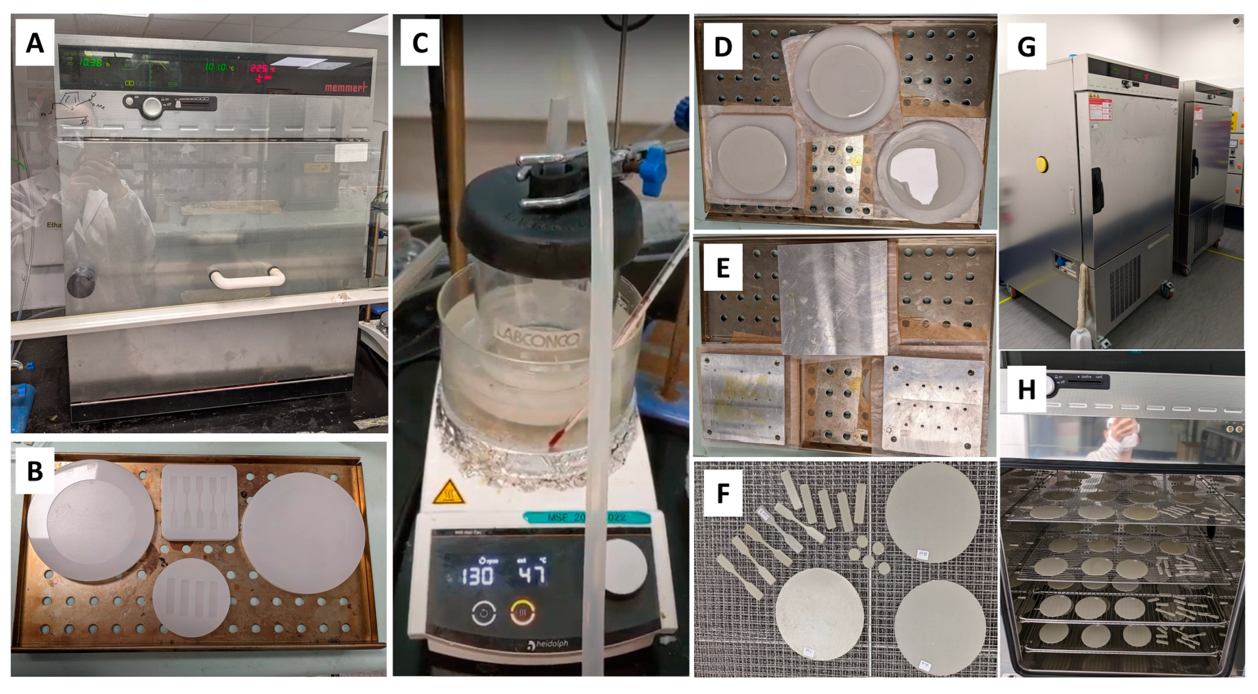
2.3. Accelerated Aging Experiment
2.4. Material Characterizations
2.4.1. Tensile Test
2.4.2. FTIR
2.4.3. DMA
2.4.4. TMA
2.4.5. Laser Flash
2.4.6. TGA
2.4.7. Contact Angle
2.4.8. FESEM-EDS
2.4.9. Mass Change
3. Results and Discussion
3.1. Summary of Material Properties Change with Aging
3.2. Tensile Strength
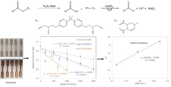
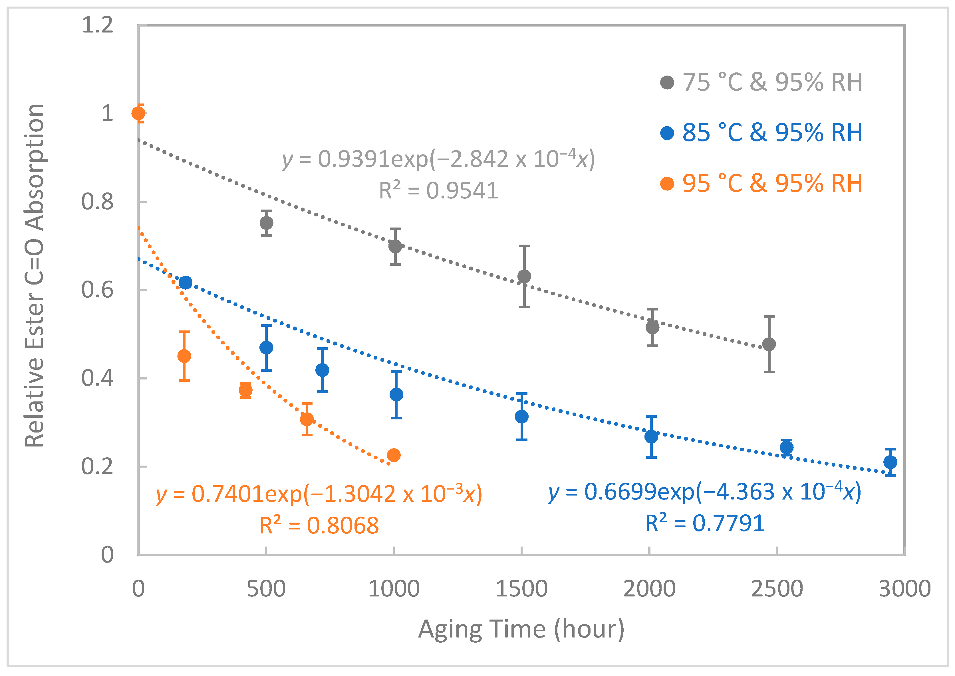
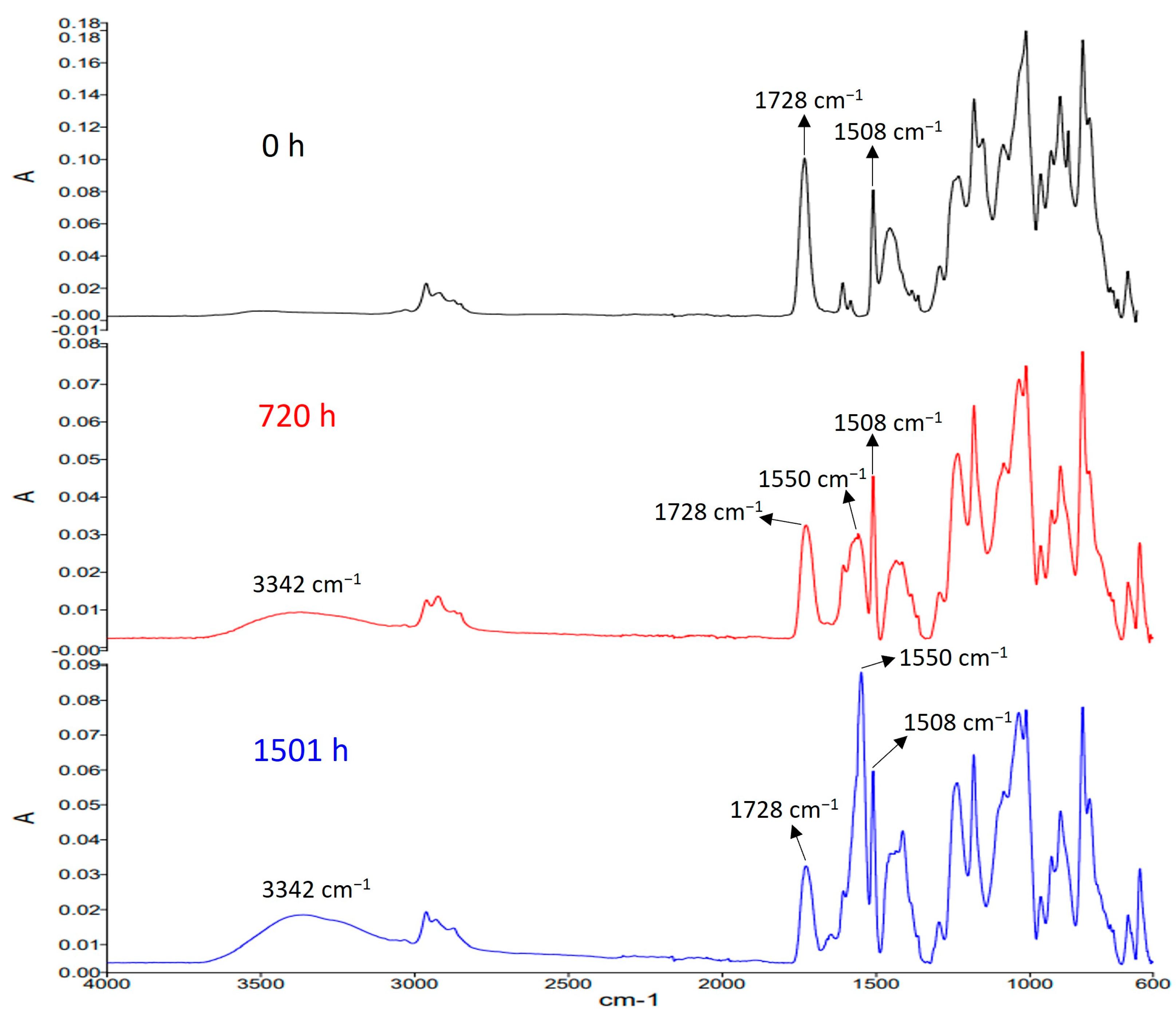
3.3. Ester C=O Absorption
3.4. Hydrophobicity
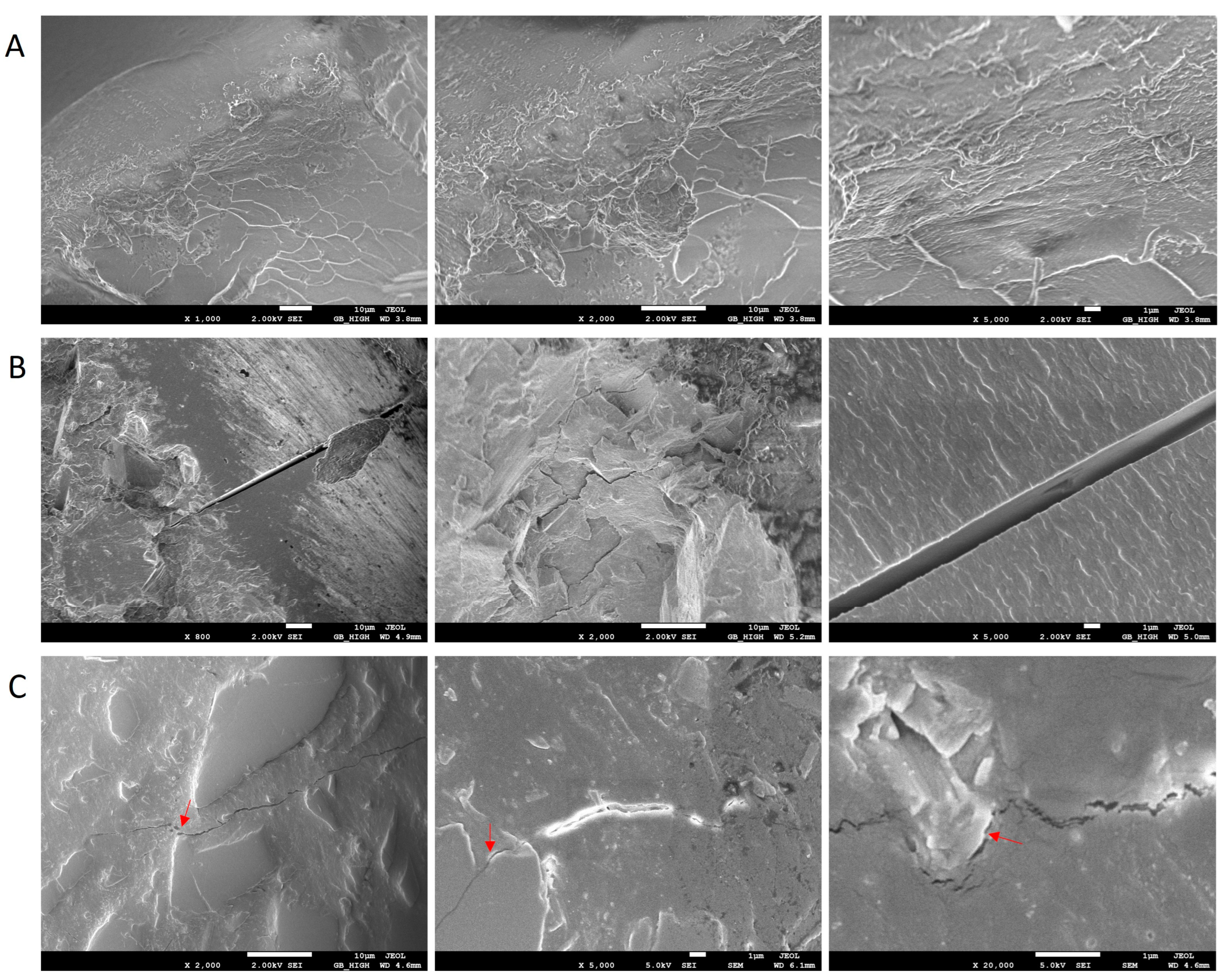
3.5. FESEM Analysis
3.6. Mass Change
3.7. Degradation Mechanism
4. Conclusions
Supplementary Materials
Author Contributions
Funding
Institutional Review Board Statement
Data Availability Statement
Conflicts of Interest
References
- Huang, X.; Jiang, P.; Tanaka, T. A Review of Dielectric Polymer Composites with High Thermal Conductivity. IEEE Electr. Insul. Mag. 2011, 27, 8–16. [Google Scholar] [CrossRef]
- Zhao, Y.; He, Y.; Yang, K.; Wang, X.; Bai, J.; Du, B. Improving the Surface Insulating Performance of Epoxy Resin/Al2O3 Composite Materials by Extending Chain of Liquid Epoxy Resin with Me-THPA. High Volt. 2020, 5, 472–481. [Google Scholar] [CrossRef]
- Zhang, L.; Deng, H.; Fu, Q. Recent Progress on Thermal Conductive and Electrical Insulating Polymer Composites. Compos. Commun. 2018, 8, 74–82. [Google Scholar] [CrossRef]
- Zhang, X.; Wu, Y.; Chen, X.; Wen, H.; Xiao, S. Theoretical Study on Decomposition Mechanism of Insulating Epoxy Resin Cured by Anhydride. Polymers 2017, 9, 341. [Google Scholar] [CrossRef]
- Wang, Y.; Zeng, Z.; Huang, Z.; Shang, J. Preparation and Characteristics of Silicone-Modified Aging-Resistant Epoxy Resin Insulation Material. J. Mater. Sci. 2022, 57, 3295–3308. [Google Scholar] [CrossRef]
- Lupo, G.; Tucci, V.; Femia, N.; Egiziano, L.; Saiello, S. On the Monitoring of the Degradation of Outdoor Organic Insulation. In Proceedings of the [1991] Proceedings of the 3rd International Conference on Properties and Applications of Dielectric Materials, Tokyo, Japan, 8–12 July 1991; IEEE: Piscataway, NJ, USA, 1991; pp. 703–706. [Google Scholar]
- Ullah, R.; Akbar, M. Effect of AC Stressed Aging on Partial Discharge, Thermal and Tensile Performance of Silicone Rubber-Based Composites. Compos. Commun. 2021, 24, 100634. [Google Scholar] [CrossRef]
- Qiao, X.; Ming, Y.; Xu, K.; Yi, N.; Sundararajan, R. Aging of Polymeric Insulators under Various Conditions and Environments: Another Look. Energies 2022, 15, 8809. [Google Scholar] [CrossRef]
- Liang, X.; Bao, W.; Gao, Y. Decay-like Fracture Mechanism of Silicone Rubber Composite Insulator. IEEE Trans. Dielectr. Electr. Insul. 2018, 25, 110–119. [Google Scholar] [CrossRef]
- Li, T.; Zhou, K.; Yang, D.; Tao, W.; Chen, Z. The Aging Mechanisms of Chalking Service-Aged Silicone Rubber Insulators. In Proceedings of the ICHVE 2016—2016 IEEE International Conference on High Voltage Engineering and Application, Chengdu, China, 19–22 September 2016; Institute of Electrical and Electronics Engineers Inc.: Piscataway, NJ, USA, 2016. [Google Scholar]
- Zhou, Y.; Gesang, Q.; Zhang, L.; Tian, J.; Chen, J.; Cui, X. Macromolecular Voltage Stabilizer for Enhanced Initiation Characteristics of Electrical Tree in Silicone Rubber. IEEE Trans. Dielectr. Electr. Insul. 2022, 29, 111–118. [Google Scholar] [CrossRef]
- Gustavsson, T.G.; Gubanski, S.M.; Hillborg, H.; Karlsson, S.; Gedde, U.W. Aging of Silicone Rubber under Ac or Dc Voltages in a Coastal Environment. IEEE Trans. Dielectr. Electr. Insul. 2001, 8, 1029–1039. [Google Scholar] [CrossRef]
- Rowland, S.M.; Robertson, J.; Xiong, Y.; Day, R.J. Electrical and Material Characterization of Field-Aged 400 KV Silicone Rubber Composite Insulators. IEEE Trans. Dielectr. Electr. Insul. 2010, 17, 375–383. [Google Scholar] [CrossRef]
- Ahmadi-Joneidi, I.; Shayegani-Akmal, A.A.; Mohseni, H. Lifetime Prediction of 20 KV Field-Aged Silicone Rubber Insulators via Condition Assessment. IEEE Trans. Dielectr. Electr. Insul. 2017, 24, 3612–3621. [Google Scholar] [CrossRef]
- Moghadam, M.K.; Morshedian, J.; Ehsani, M.; Bahrami, M.; Saddadi, H. Lifetime Prediction of HV Silicone Rubber Insulators Based on Mechanical Tests after Thermal Ageing. IEEE Trans. Dielectr. Electr. Insul. 2013, 20, 711–716. [Google Scholar] [CrossRef]
- Marungsri, B.; Shinokubo, H.; Matsuoka, R.; Kumagai, S. Effect of Specimen Configuration on Deterioration of Silicone Rubber for Polymer Insulators in Salt Fog Ageing Test. IEEE Trans. Dielectr. Electr. Insul. 2006, 13, 129–138. [Google Scholar] [CrossRef]
- Yang, Y.; Wang, K.; Yu, Y.; Li, J.; Zhang, S.; Li, G.; Xiang, X.; Wu, G. Effect of Mineral Oil on Electrical Properties of HTV Silicone Rubber under Thermal and AC Corona Aging. In Proceedings of the Annual Report—Conference on Electrical Insulation and Dielectric Phenomena, CEIDP 2019, Richland, WA, USA, 20–23 October 2019; pp. 624–627. [Google Scholar] [CrossRef]
- Wu, C.; Dissado, L.A.; Gao, Y.; Wang, Q.; Liu, Y.; Cao, Y.; Liang, X. Dielectric Response—A Nondestructive Approach to Probing the Micro-interface of Aluminium Hydroxide Filled Silicone Rubber Composites for Outdoor Insulation. High Volt. 2023, 8, 1–9. [Google Scholar] [CrossRef]
- Wang, Y.; Zeng, Z.; Gao, M.; Huang, Z. Hygrothermal Aging Characteristics of Silicone-Modified Aging-Resistant Epoxy Resin Insulating Material. Polymers 2021, 13, 2145. [Google Scholar] [CrossRef]
- Vouyovitch, L.; Alberola, N.; Flandin, L.; Beroual, A.; Bessède, J.-L. Dielectric Breakdown of Epoxy-Based Composites: Relative Influence of Physical and Chemical Aging. IEEE Trans. Dielectr. Electr. Insul. 2006, 13, 282–292. [Google Scholar] [CrossRef]
- Shin, K.-B.; Kim, C.-G.; Hong, C.-S. Correlation of Accelerated Aging Test to Natural Aging Test on Graphite-Epoxy Composite Materials. J. Reinf. Plast. 2003, 22, 849–861. [Google Scholar] [CrossRef]
- Liu, C.; Chen, Y.; Yao, K.; Hao, Y.; Wang, S.; Wang, Z.; Gong, R.; Du, C. Combined Electrical and Thermal Aging of Alumina Filled Epoxy Solid Insulators for GIS. In Proceedings of the 2019 IEEE International Conference on Environment and Electrical Engineering, Genova, Italy, 11–14 June 2019. [Google Scholar]
- Boucher, V.; Rain, P.; Teissedre, G.; Schlupp, P. Mechanical and Dielectric Properties of Glass-Mica-Epoxy Composites along Accelerated Thermo-Oxidative Aging. In Proceedings of the 2007 IEEE International Conference on Solid Dielectrics, Winchester, UK, 8–13 July 2007; IEEE: Piscataway, NJ, USA, 2007; pp. 162–165. [Google Scholar]
- Suo, C.; Qin, Y.; Li, Z. Effect of Thermal Aging on DC Conductivity of NANO-CB/XLPE Insulating Composites. In Proceedings of the 2018 IEEE International Conference on High Voltage Engineering and Application (ICHVE), Athens, Greece, 10–13 September 2018; IEEE: Piscataway, NJ, USA, 2018; pp. 1–4. [Google Scholar]
- ASTM D638-14; Standard Test Method for Tensile Properties of Plastics. ASTM: West Conshohocken, PA, USA, 2014.
- ASTM D229-19; Standard Test Methods for Rigid Sheet and Plate Materials Used for Electrical Insulation. ASTM: West Conshohocken, PA, USA, 2019.
- BS ISO 20368:2017; Plastics-Epoxy Resins-Determination of Degree of Crosslinking of Crosslinked Epoxy Resins by Fourier Transform Infrared (FTIR) Spectroscopy. ISO: Geneva, Switzerland, 2017.
- ASTM D7028-07; 2015 Standard Test Method for Glass Transition Temperature (DMA Tg) of Polymer Matrix Composites by Dynamic Mechanical Analysis (DMA). ASTM: West Conshohocken, PA, USA, 2015.
- ISO 6721-11:2019; BSI Standards Publication Plastics-Determination of Dynamic Mechanical Properties. ISO: Geneva, Switzerland, 2019.
- ASTM E831; Standard Test Method for Linear Thermal Expansion of Solid Materials by Thermomechanical Analysis. ASTM: West Conshohocken, PA, USA, 2019.
- ISO 11357-8:2021; Plastics–Differential Scanning Calorimetry (DSC) Part 8: Determination of Thermal Conductivity. ISO: Geneva, Switzerland, 2021.
- ISO 22007-1:2017; Plastics-Determination of Thermal Conductivity and Thermal Diffusivity Part 1: General Principles. ISO: Geneva, Switzerland, 2017.
- ISO 22007-4:2017; Plastics-Determination of Thermal Conductivity and Thermal Diffusivity Part 4: Laser Flash Method. ISO: Geneva, Switzerland, 2017.
- ASTM E1269-11; Standard Test Method for Determining Specific Heat Capacity by Differential Scanning Calorimetry. ASTM: West Conshohocken, PA, USA, 2018.
- ISO 11357-4; Plastics–Differential Scanning Calorimetry (DSC) Part 4: Determination of Specific Heat Capacity. ISO: Geneva, Switzerland, 2014.
- ASTM E1461-13; Standard Test Method for Thermal Diffusivity by the Flash Method. ASTM: West Conshohocken, PA, USA, 2013.
- ASTM E2550-17; Standard Test Method for Thermal Stability by Thermogravimetry. ASTM: West Conshohocken, PA, USA, 2017.
- IEC 62073:2016; Guidance on the Measurement of Hydrophobicity of Insulator Surfaces. IEC: Geneva, Switzerland, 2016.
- ASTM C1723-16; Standard Guide for Examination of Hardened Concrete Using Scanning Electron Microscopy. ASTM: West Conshohocken, PA, USA, 2016.
- BS EN 60243-1:2013; Electric Strength of Insulating Materials-Test Methods Part 1: Tests at Power Frequencies. BSI: London, UK, 2013.
- IEC 62631-3-1; Dielectric and Resistive Properties of Solid Insulating Materials Part 3-1: Determination of Resistive Properties (DC Methods)—Volume Resistance and Volume Resistivity—General Method. IEC: Geneva, Switzerland, 2023.
- IEC 62631-3-2; Dielectric and Resistive Properties of Solid Insulating Materials Part 3-2: Determination of Resistive Properties (DC Methods)—Surface Resistance and Surface Resistivity. IEC: Geneva, Switzerland, 2015.
- IEC 62631-3-4:2019; Dielectric and Resistive Properties of Solid Insulating Materials Part 3-4: Determination of Resistive Properties (DC Methods)—Volume Resistance and Volume Resistivity at Elevated Temperatures. IEC: Geneva, Switzerland, 2019.
- BS EN IEC 62631-2-1:2018; Dielectric and Resistive Properties of Solid Insulating Materials. BSI: London, UK, 2018.
- IEC 60505:2011; Evaluation and Qualification of Electrical Insulation Systems. IEC: Geneva, Switzerland, 2011.
- Ghabezi, P.; Harrison, N.M. Indentation Characterization of Glass/Epoxy and Carbon/Epoxy Composite Samples Aged in Artificial Salt Water at Elevated Temperature. Polym. Test 2022, 110, 107588. [Google Scholar] [CrossRef]
- Liu, X.; Su, Q.; Zhu, J.; Song, X. The Aging Behavior and Life Prediction of CFRP Rods under a Hygrothermal Environment. Polymers 2023, 15, 2490. [Google Scholar] [CrossRef]
- ISO 3673-2:2012; Plastics-Epoxy Resins Part 2: Preparation of Test Specimens and Determination of Properties of Crosslinked Epoxy Resins. ISO: Geneva, Switzerland, 2012.
- Wang, Y.; Meng, Z.; Zhu, W.; Wan, B.; Han, B.; Cai, G.; Yin, X.; Bai, Y. Hygrothermal Aging Behavior and Aging Mechanism of Carbon Nanofibers/Epoxy Composites. Constr. Build. Mater 2021, 294, 123538. [Google Scholar] [CrossRef]
- Choi, S.; Yang, J.; Kim, Y.; Nam, J.; Kim, K.; Shim, S.E. Microwave-Accelerated Synthesis of Silica Nanoparticle-Coated Graphite Nanoplatelets and Properties of Their Epoxy Composites. Compos. Sci. Technol. 2014, 103, 8–15. [Google Scholar] [CrossRef]
- Zhang, W.; Fina, A.; Ferraro, G.; Yang, R. FTIR and GCMS Analysis of Epoxy Resin Decomposition Products Feeding the Flame during UL 94 Standard Flammability Test. Application to the Understanding of the Blowing-out Effect in Epoxy/Polyhedral Silsesquioxane Formulations. J. Anal. Appl. Pyrolysis 2018, 135, 271–280. [Google Scholar] [CrossRef]
- Zhang, D.; Liu, J.; Liu, X.; Liu, Y.; Yang, X.; Gao, Y.; Ma, A. Comprehensive Promotion of Mechanical Properties of Epoxy by Electrical Insulating Filler of Si3N4 Whiskers at Low Content. Polym. Compos. 2020, 41, 4489–4502. [Google Scholar] [CrossRef]
- Saeedi, I.A.; Andritsch, T.; Vaughan, A.S. On the Dielectric Behavior of Amine and Anhydride Cured Epoxy Resins Modified Using Multi-Terminal Epoxy Functional Network Modifier. Polymers 2019, 11, 1271. [Google Scholar] [CrossRef]
- Zhang, L.; Liu, J.; Nie, W.; Wang, K.; Wang, Y.; Yang, X.; Tang, T. Degradation of Anhydride-Cured Epoxy Resin Using Simultaneously Recyclable Solvent and Organic Base Catalyst. J. Mater. Cycles. Waste Manag. 2018, 20, 568–577. [Google Scholar] [CrossRef]
- IEC TR 62039:2021; Selection Guidelines for Polymeric Materials for Outdoor Use under HV Stress. IEC: Geneva, Switzerland, 2021.
- IEC 60749-5:2017; Semiconductor Devices-Mechanical and Climatic Test Methods Part 5: Steady-State Temperature Humidity Bias Life Test. IEC: Geneva, Switzerland, 2017.
- Ivanova, B.; Tsalev, D.; Arnaudov, M. Validation of Reducing-Difference Procedure for the Interpretation of Non-Polarized Infrared Spectra of n-Component Solid Mixtures. Talanta 2006, 69, 822–828. [Google Scholar] [CrossRef]
- Lewandowski, L.H.; Lynch, L.N. Quantitative Analysis of Joint Sealants Using FTIR-ATR. Transp. Res. Rec. 1992, 1334, 19–24. [Google Scholar]
- O’Haver, T.C. Pragmatic Introduction to Signal Processing Applications in Scientific Measurement; 2023; ISBN 9798378715381. [Google Scholar]
- IEC 60216-2:2005; Electrical Insulating Materials—Thermal Endurance Properties—Part 2: Determination of Thermal Endurance Properties of Electrical Insulating Materials. IEC: Geneva, Switzerland, 2005.
- ISO 11346:2014; Rubber, Vulcanized or Thermoplastic—Estimation of Life-Time and Maximum Temperature of Use. ISO: Geneva, Switzerland, 2014.
- Bessède, J.-L. Chapter 5: Development of Advanced Materials for Transmission and Distribution (T&D) Networks Equipment. In Electricity Transmission, Distribution and Storage Systems; Elsevier: Amsterdam, The Netherlands, 2013; pp. 133–142. ISBN 9780857097378. [Google Scholar]
- Jia, Z.D.; Xie, H.K. The Change of Microstructure of Epoxy Mica Insulation in Multi-Stress Aging. In Proceedings of the 2001 International Symposium on Electrical Insulating Materials (ISEIM 2001). 2001 Asian Conference on Electrical Insulating Diagnosis (ACEID 2001). 33rd Symposium on Electrical and Electronic Insulating Materials and Applications in System, Himeji, Japan, 22 November 2001; pp. 693–696. [Google Scholar]
- Ahmad, F.; Ullah, S.; Merican, N.H.; Bt, H.; Oñate, E.; Al-Sehemi, A.G.; Yeoh, G.H. An Investigation on Thermal Performance of Wollastonite and Bentonite Reinforced Intumescent Fire-Retardant Coating for Steel Structures. Constr. Build Mater. 2019, 228, 116734. [Google Scholar] [CrossRef]
- Cañavate, J.; Colom, X.; Pagès, P.; Carrasco, F. Study of the curing process of an epoxy resin by ftir spectroscopy. Polym. Plast. Technol. Eng. 2000, 39, 937–943. [Google Scholar] [CrossRef]
- Zeleňák, V.; Vargová, Z.; Györyová, K. Correlation of Infrared Spectra of Zinc(II) Carboxylates with Their Structures. Spectrochim. Acta A Mol. Biomol. Spectrosc. 2007, 66, 262–272. [Google Scholar] [CrossRef]
- Vaca-Trigo, I.; Meeker, W.Q. A Statistical Model for Linking Field and Laboratory Exposure Results for a Model Coating. In Service Life Prediction of Polymeric Materials; Martin, J.W., Ryntz, R.A., Chin, J., Dickie, R.A., Eds.; Springer: Boston, MA, USA, 2009; pp. 29–43. [Google Scholar] [CrossRef]
- Perrier, A.; Touchard, F.; Chocinski-Arnault, L.; Mellier, D. Quantitative Analysis by Micro-CT of Damage during Tensile Test in a Woven Hemp/Epoxy Composite after Water Ageing. Compos. Part A Appl. Sci. Manuf. 2017, 102, 18–27. [Google Scholar] [CrossRef]
- Tian, F.; Hao, Y.; Zou, Z.; Zheng, Y.; He, W.; Yang, L.; Li, L. An Ultrasonic Pulse-Echo Method to Detect Internal Defects in Epoxy Composite Insulation. Energies 2019, 12, 4804. [Google Scholar] [CrossRef]


| Property | Industrial Standard | Characterization Technique |
|---|---|---|
| Tensile strength Elastic modulus | D638-14 [25] D229-19 [26] | Universal testing machine |
| Chemical structure | ISO 20368 [27] | Fourier transform infrared spectrometer (FTIR) |
| Thermal strain Glass transition temperature (Tg) | ASTM D7028-07 [28] ISO 6721 [29] | Dynamic mechanical analyzer (DMA) |
| Thermal expansion | ASTM E831-19 [30] | Thermomechanical analyzer (TMA) |
| Thermal conductivity | ISO 11357-8 [31] ISO 22007-1 [32] ISO 22007-4 [33] | Differential scanning calorimeter Modulated differential scanning calorimeter Laser flash |
| Heat capacity | ASTM E1269 [34] ISO 11357-4 [35] ASTM E1461-13 [36] | Differential scanning calorimeter Laser flash |
| Thermal stability | ASTM E2550 [37] | Thermogravimetric analyzer (TGA) |
| Contact angle | IEC 62073 [38] | Contact angle goniometer |
| Filler and microcrack | ASTM C1723 [39] | Field emission scanning electron microscope—energy dispersive spectrometer (FESEM-EDS) |
| Breakdown strength | IEC 60243-1 [40] | AC dielectric breakdown tester |
| Electric conductivity | IEC 62631-3-1 [41] IEC 62631-3-2 [42] IEC 62631-3-4 [43] | Electrometer/high-resistance meter |
| Dielectric loss | IEC 62631-2-1 [44] | Dielectric loss |
| Conditions | Aging Hours |
|---|---|
| 95 °C and 95% RH | 0, 180, 420, 660, 1000 |
| 85 °C and 95% RH | 185, 501, 720, 1010, 1509, 2012 |
| 75 °C and 95% RH | 502, 1006, 1511, 2013 |
| Lifetime Prediction | t (year) |
|---|---|
| 75 °C and 95% RH | 0.44 |
| 65 °C and 95% RH | 0.94 |
| 55 °C and 95% RH | 2.10 |
| 45 °C and 95% RH | 4.98 |
| 35 °C and 95% RH | 12.46 |
| 25 °C and 95% RH | 33.16 |
| Aging Condition | Lifetime (hour) | Relative Ester C=O Absorption | Change from Unaged |
|---|---|---|---|
| 75 °C and 95% RH | 3696.9 | 0.32795 | −67.21% |
| 85 °C and 95% RH | 1987.2 | 0.28148 | −71.85% |
| 95 °C and 95% RH | 907.0 | 0.22675 | −77.33% |
Disclaimer/Publisher’s Note: The statements, opinions and data contained in all publications are solely those of the individual author(s) and contributor(s) and not of MDPI and/or the editor(s). MDPI and/or the editor(s) disclaim responsibility for any injury to people or property resulting from any ideas, methods, instructions or products referred to in the content. |
© 2023 by the authors. Licensee MDPI, Basel, Switzerland. This article is an open access article distributed under the terms and conditions of the Creative Commons Attribution (CC BY) license (https://creativecommons.org/licenses/by/4.0/).
Share and Cite
Ma, J.; Yang, Y.; Wang, Q.; Deng, Y.; Yap, M.; Chern, W.K.; Oh, J.T.; Chen, Z. Degradation and Lifetime Prediction of Epoxy Composite Insulation Materials under High Relative Humidity. Polymers 2023, 15, 2666. https://doi.org/10.3390/polym15122666
Ma J, Yang Y, Wang Q, Deng Y, Yap M, Chern WK, Oh JT, Chen Z. Degradation and Lifetime Prediction of Epoxy Composite Insulation Materials under High Relative Humidity. Polymers. 2023; 15(12):2666. https://doi.org/10.3390/polym15122666
Chicago/Turabian StyleMa, Jielin, Yan Yang, Qi Wang, Yuheng Deng, Malvern Yap, Wen Kwang Chern, Joo Tien Oh, and Zhong Chen. 2023. "Degradation and Lifetime Prediction of Epoxy Composite Insulation Materials under High Relative Humidity" Polymers 15, no. 12: 2666. https://doi.org/10.3390/polym15122666
APA StyleMa, J., Yang, Y., Wang, Q., Deng, Y., Yap, M., Chern, W. K., Oh, J. T., & Chen, Z. (2023). Degradation and Lifetime Prediction of Epoxy Composite Insulation Materials under High Relative Humidity. Polymers, 15(12), 2666. https://doi.org/10.3390/polym15122666