
Treatment of Mode Coupling in Step-Index Multimode Microstructured Polymer Optical Fibers by the Langevin Equation


Abstract
:
1. Introduction
2. The Langevin Equation
3. Numerical Results and Discussion
4. Conclusions
Author Contributions
Funding
Institutional Review Board Statement
Informed Consent Statement
Data Availability Statement
Conflicts of Interest
References
- Schuppert, M.; Bunge, C.-A. 5Gb/s eye-safe LED-based SI-POF transmission with equalization of transmitter nonlinearities. IEEE Photon. Technol. Lett. 2016, 28, 2732–2735. [Google Scholar] [CrossRef]
- Rodríguez-Pérez, A.; Pérez de Aranda, R.; Prefasi, E.; Dumont, S.; Rosado, J.; Enrique, I.; Pinzón, P.; Ortiz, D. Toward the Multi-Gigabit Ethernet for the Automo-tive Industry. Fiber Integr. Opt. 2021, 40, 1–13. [Google Scholar] [CrossRef]
- Apolo, J.A.; Ortega, B.; Almenar, V. Hybrid POF/VLC links based on a single LED for indoor communications. Photonics 2021, 8, 254. [Google Scholar] [CrossRef]
- Sequeira, F.; Cennamo, N.; Rudnitskaya, A.; Nogueira, R.; Zeni, L.; Bilro, L. D-shaped POF sensors for refractive index sensing—The importance of surface roughness. Sensors 2019, 19, 2476. [Google Scholar] [CrossRef] [Green Version]
- Cennamo, N.; D’Agostino, G.; Sequeira, F.; Mattiello, F.; Porto, G.; Biasiolo, A.; Nogueira, R.; Bilro, L.; Zeni, L. A simple and low-cost optical fiber intensity-based configuration for perfluorinated compounds in water solution. Sensors 2018, 18, 3009. [Google Scholar] [CrossRef] [PubMed] [Green Version]
- Leal-Junior, A.G.; Diaz, C.A.R.; Avellar, L.M.; Pontes, M.J.; Marques, C.; Frizera, A. Polymer optical fiber sensors in healthcare applications: A comprehensive review. Sensors 2019, 19, 3156. [Google Scholar] [CrossRef] [PubMed] [Green Version]
- Sartiano, D.; Geernaert, T.; Torres Roca, E.; Sales, S. Bend-Direction and Rotation Plastic Optical Fiber Sensor. Sensors 2020, 20, 5405. [Google Scholar] [CrossRef] [PubMed]
- Reis, F.M.; Fernando da Costa Antunes, P.; Manuel Mendes Maia, N.; Carvalho, A.R.; SØrgio de Brito AndrØ, P. Structural health monitoring suitable for airborne components using the speckle pattern in plastic optical fibers. IEEE Sens. J. 2017, 17, 4791–4796. [Google Scholar] [CrossRef]
- García, I.; Zubia, J.; Durana, G.; Aldabaldetreku, G.; lllarramendi, M.A.; Villatoro, J. Optical fiber sensors for aircraft structural health monitoring. Sensors 2015, 15, 15494–15519. [Google Scholar] [CrossRef] [Green Version]
- Russell, P. Photonic crystal fibers. Science 2003, 299, 358–362. [Google Scholar] [CrossRef] [PubMed]
- Yu, R.; Chen, Y.; Shui, L.; Xiao, L. Hollow-core photonic crystal fiber gas sensing. Sensors 2020, 20, 2996. [Google Scholar] [CrossRef]
- Kumar, A.; Verma, P.; Jindal, P. Decagonal solid core PCF based refractive in-dex sensor for blood cells detection in terahertz regime. Opt. Quant. Electron. 2021, 53, 165. [Google Scholar] [CrossRef]
- van Eijkelenborg, M.A.; Large, M.C.J.; Argyros, A.; Zagari, J.; Manos, S.; Issa, N.A.; Bassett, I.; Fleming, S.; McPhedran, R.C.; Martijn de Sterke, C.M.; et al. Microstructured polymer optical fibre. Opt. Express 2001, 9, 319–327. [Google Scholar] [CrossRef] [PubMed]
- Large, M.; Martins Werneck, M. Chapter: Microstructured POFs. In Plastic Optical Fiber Sensors; Imprint CRC Press: Boca Raton, FL, USA, 2019. [Google Scholar]
- Arrospide, E.; Durana, G.; Azkune, M.; Aldabaldetreku, G.; Bikandi, I.; Ruiz-Rubio, L.; Zubia, J. Polymers beyond standard optical fibres—Fabrication of microstructured polymer optical fibres. Polym. Int. 2018, 67, 1155–1163. [Google Scholar] [CrossRef]
- Argyros, A. Microstructured polymer optical fibers. J. Lightwave Technol. 2009, 27, 1571–1579. [Google Scholar] [CrossRef]
- Stepien, R.; Siwicki, B.; Pysz, D.; Stepniewski, G. Characterization of a large core photonic crystal fiber made of lead–bismuth–gallium oxide glass for broadband infrared transmission. Opt. Quant. Electron. 2014, 46, 553–561. [Google Scholar] [CrossRef] [Green Version]
- Berganza, A.; Arrospide, E.; Amorebieta, J.; Zubia, J.; Durana, G. Fabrication Quality Assessment Based on the Coupling of a Dual-Core Microstructured Polymer Optical Fiber. Sensors 2021, 21, 7435. [Google Scholar] [CrossRef] [PubMed]
- Savović, S.; Kovačević, M.S.; Drljača, B.; Simović, A.; Kuzmanović, L.; Djordjevich, A. Power flow in multimode step-index plastic photonic crystal fibers. Optik 2021, 247, 167868. [Google Scholar] [CrossRef]
- Jiang, G.; Shi, R.F.; Garito, A.F. Mode coupling and equilibrium mode distribution conditions in plastic optical fibers. IEEE Photon. Technol. Lett. 1997, 9, 1128–1130. [Google Scholar] [CrossRef]
- Garito, A.F.; Wang, J.; Gao, R. Effects of random perturbations in plastic optical fibers. Science 1998, 281, 962–967. [Google Scholar] [CrossRef] [PubMed]
- Savović, S.; Djordjevich, A. Investigation of mode coupling in low and high NA step index plastic optical fibers using the Langevin equation. J. Mod. Opt. 2020, 67, 958–962. [Google Scholar] [CrossRef]
- Risken, H. The Fokker-Planck Equation; Springer: Berlin/Heidelberg, Germany, 1989. [Google Scholar]
- Saitoh, K.; Koshiba, M. Empirical relations for simple design of photonic crystal fibers. Opt. Express 2005, 13, 267–274. [Google Scholar] [CrossRef] [PubMed]
- Kovačević, M.S.; Kuzmanović, L.; Simović, A.; Savović, S.; Djordjevich, A. Transients of modal-power distribution in multimode solid core W-type photonic crystal fibers. J. Lightwave Technol. 2017, 35, 4352–4357. [Google Scholar] [CrossRef]
- Drljača, B.; Savović, S.; Kovačević, M.S.; Simović, A.; Kuzmanović, L.; Djordjevich, A.; Min, R. Calculation of bandwidth of multimode step-index plastic photonic crystal fibers. Polymers 2021, 13, 4218. [Google Scholar] [CrossRef] [PubMed]
 ), 5°(- - -), and 10° (• • •), for fiber length (a) z = 2 m; (b) z = 15 m; (c) ; (d) = 102 m ( and d = 2 µm).
), 5°(- - -), and 10° (• • •), for fiber length (a) z = 2 m; (b) z = 15 m; (c) ; (d) = 102 m ( and d = 2 µm).
), 5°(- - -), and 10° (• • •), for fiber length (a) z = 2 m; (b) z = 15 m; (c) ; (d) = 102 m ( and d = 2 µm).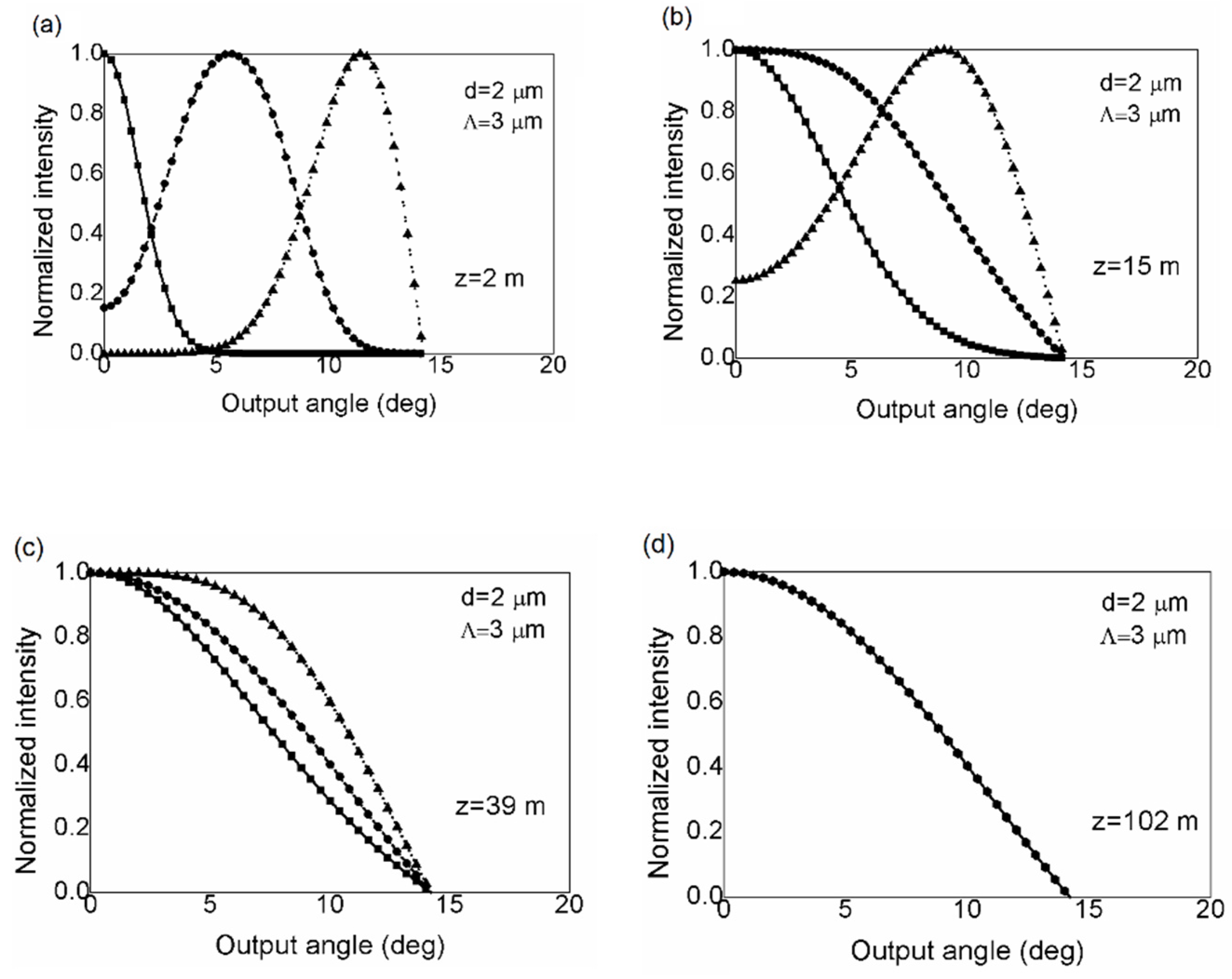

| 0.54808 | 0.71041 | 0.16904 | −1.52736 | |
| 5.00401 | 9.73491 | 1.85765 | 1.06745 | |
| −10.43248 | 47.41496 | 18.96849 | 1.93229 | |
| 8.22992 | −437.50962 | −42.4318 | 3.89 | |
| 5 | 1.8 | 1.7 | −0.84 | |
| 7 | 7.32 | 10 | 1.02 | |
| 9 | 22.8 | 14 | 13.4 |
Publisher’s Note: MDPI stays neutral with regard to jurisdictional claims in published maps and institutional affiliations. |
© 2022 by the authors. Licensee MDPI, Basel, Switzerland. This article is an open access article distributed under the terms and conditions of the Creative Commons Attribution (CC BY) license (https://creativecommons.org/licenses/by/4.0/).
Share and Cite
Savović, S.; Li, L.; Savović, I.; Djordjevich, A.; Min, R. Treatment of Mode Coupling in Step-Index Multimode Microstructured Polymer Optical Fibers by the Langevin Equation. Polymers 2022, 14, 1243. https://doi.org/10.3390/polym14061243
Savović S, Li L, Savović I, Djordjevich A, Min R. Treatment of Mode Coupling in Step-Index Multimode Microstructured Polymer Optical Fibers by the Langevin Equation. Polymers. 2022; 14(6):1243. https://doi.org/10.3390/polym14061243
Chicago/Turabian StyleSavović, Svetislav, Linqing Li, Isidora Savović, Alexandar Djordjevich, and Rui Min. 2022. "Treatment of Mode Coupling in Step-Index Multimode Microstructured Polymer Optical Fibers by the Langevin Equation" Polymers 14, no. 6: 1243. https://doi.org/10.3390/polym14061243
APA StyleSavović, S., Li, L., Savović, I., Djordjevich, A., & Min, R. (2022). Treatment of Mode Coupling in Step-Index Multimode Microstructured Polymer Optical Fibers by the Langevin Equation. Polymers, 14(6), 1243. https://doi.org/10.3390/polym14061243