Article

PVDF/KNO3 Composite Sub-Microfibers Produced by Solution Blow Spinning as a Hydrophobic Matrix for Fertilizer Delivery System

1
Programa de Pós-Graduação em Química, Instituto de Química, UFMS—Universidade Federal de Mato Grosso do Sul, Campo Grande 79070-900, Brazil
2
UNESP—Universidade Estadual Paulista “Júlio de Mesquita Filho”, Rosana 19272-000, Brazil
3
Programa de Pós-Graduação em Ciência dos Materiais, Instituto de Física, UFMS—Universidade Federal de Mato Grosso do Sul, Campo Grande 79070-900, Brazil
*
Author to whom correspondence should be addressed.
Polymers 2022, 14(5), 1000; https://doi.org/10.3390/polym14051000
Submission received: 29 January 2022 / Revised: 20 February 2022 / Accepted: 23 February 2022 / Published: 1 March 2022
(This article belongs to the Section Polymer Fibers)

Abstract

:
Nutrient supplementation is a common practice in agriculture to increase crop productivity in the field. This supplementation is usually excessive, causing nutrient leaching in periods of rainfall leading to environmental problems. To overcome such issues, many studies have been devoted to developing polymeric matrices for the controlled and continuous release of nutrients, reducing losses, and keeping plants nourished for as long as possible. However, the release mechanism of these matrices is based on water diffusion. They start immediately for swellable polymeric matrices, which is not interesting and also may cause some waste, because the plant only needs nutrition only after the germination process. Here, as proof of concept, we tested a hydrophobic polymeric matrix based on sub-microfibers mats, produced by solution blow spinning, filled with potassium nitrate (KNO3) for the controlled release of nutrients to plants. In this work, we used the polyvinylidene fluoride (PVDF) polymer to produce composite nanofibers containing pure potassium nitrate in the proportion of 10% weight. PVDF/KNO sub-microfibers mats were obtained with 370 nm average diameter and high occurrence of beads. We performed a release test using PVDF/KNO3 mats in a water bath. The release kinetic tests showed an anomalous delivery mechanism, but the composite polymeric fibrous mat showed itself to be a promising alternative to delay the nutrient delivery for the plants.

Graphical Abstract

1. Introduction

Polymeric nanofibers exhibit a high surface area and offer several possibilities for applications. The easy incorporation of active ingredients into polymeric fibers motivates their use as controlled delivery systems for agriculture applications once they provide a regular and continuous supply of agrochemicals to soil and/or plants, reducing eventual losses and environmental pollution [1].
Fibrous mats produced by electrospinning techniques have been used for different proposed applications on agricultural activities, such as controlled delivery of pheromones in traps for pest control [2,3,4], fungicide protection for rice seeds [5], allowing temperature control, water and air exchange with the surrounding environment, and the improvement of the soil microbiome by releasing encapsulated microbes and bacteria [6,7], since they protect the microorganism from environmental stress, such as high temperature and dehydration.
Fertilizer delivery systems can also be produced, and their release rate can be tuned by changing the polymeric matrix and fibrous mat microstructure [8,9]. Additionally, fiber mats prevent fertilizer leaching due to rain, which reduces the amount of fertilizer introduced in the soil for the plant, avoiding pollution of river networks. During the dry season, the fiber mats aid seed fixation in the soil [10]. Finally, fibrous mats can be used as a removal material for pollutants, such as pesticides and herbicides, from soil and water [11,12].
An extensive range of materials has been produced as nanofibers by the electrospinning technique [13]. This method exhibits an expensive experimental setup and lower production rates making it a disadvantageous approach for large-scale production. On the other side, the solution blow spinning [14,15] can be scalable (showing a production rate 10 times higher) and requires an inexpensive setup, which permits its use directly in the field. Solution blow spinning microfibers are extensively studied, and polymeric, composite, and ceramic fibers have been produced. The influence of experimental parameters on fiber mats microstructure is well described in the literature [16,17,18].
Poly (vinylidene fluoride) (PVDF) is a semicrystalline polymer widely studied due to its piezoelectric properties and its ability to be chemically and physically stable. It can be obtained in different phases: orthorhombic alpha (α), beta (β), and delta (δ) phases and the monoclinic gamma (γ) phase [19,20,21]. PVDF has high hydrophobicity, a factor that can make specific applications difficult, as it directly influences the absorption of the material [22].
The controlled release mechanism of agrochemicals can be described by Fick’s First Law of Diffusion, where the diffusion coefficients and the coating thickness play an important role in the release rate [1]. The solute diffusion and water permeation rate through the polymeric matrix are important parameters for tuning the release of agrochemicals. The choice of a proper polymeric matrix is usually based on environmentally friendly materials, which are usually highly permeable for water molecules. In this study, we produced PVDF sub-microfiber mats, loaded with KNO3 fertilizer by solution blow spinning technique. We tested the microfiber mats as a hydrophobic matrix for a KNO3 delivery system.

2. Materials and Methods

2.1. Sample Preparation

Poly (vinylidene fluoride) (PVDF), (C2H2F2)n was supplied in powder form from Kynar® 763. The PVDF was dissolved in N,N-dimethylformamide (DMF), (CH3)2NC(O)H, supplied from Synth, under constant stirring for 2 h at room temperature (25 °C); after complete dissolution, acetone (AC), C3H6O, supplied from Dinâmica, was added in 20 vol% to improve the solvent volatility a few minutes before the sample production by solution blow spinning.
Polymeric nanofibers were obtained by solution blow-spinning technique, with the aid of an airbrush system, as described elsewhere [23,24]. The best conditions for polymeric fiber formation were determined by studying the influence of the DMF/acetone ratio and gas pressure on fiber morphology. The best conditions found for PVDF fiber production were kept for future composite fiber deposition. The standard processing condition for nanofiber formation was a gas pressure of 60 Psi, a work distance of 25 cm, and a 22G needle. We produced PVDF microfibers, loaded with KNO3 as fertilizer, by adding 10 wt% of potassium nitrates (Quimex Industry, Midlothian, IL, USA) into the PVDF solution before fiber processing.
After adjusting to the best conditions for fiber production, the PVDF and PVDF/KNO3 were continuously produced for 1 h in a flow hood chamber, then the fiber mats were collected, Figure 1, for future tests and characterization.

2.2. Sample Characterization

SEM (Scanning Electron Microscopy) images were obtained in a JEOL, model JSM-6380LV, with 8–10 kV, after sample surface metallization with gold thin film by a sputtering technique. The fibers’ diameters were measured using IMAGE J software (National Institutes of Health, Wayne Rasband, Bethesda, MD, USA) by analyzing 100 random fibers from each image; a histogram was produced for each sample and the higher-occurrence fiber diameters were used as a reference for describing each sample.
Attenuated total reflectance Fourier transform infrared spectroscopy (ATR-FTIR), performed in a Perkin-Elmer Spectrum 100 model, investigated the presence of KNO3 in the PVDF sub-micrometer fibers. The measurements ranged from 4000 to 600 cm−1 with 4 cm−1 resolution and 5 scans; the samples were measured in three different regions and the average FTIR spectra were used as reference. Thermogravimetric analysis (TGA) was performed in Shimadzu TGA-50 equipment, under a nitrogen atmosphere with 60 mL/min steady flow, from room temperature up to 800 °C, to evaluate the thermal stability of the samples.
The fiber mats’ wettability was estimated by contact angle measurement in a contact angle analyzer Tantec, CAM-Micro model, by sessile drop technique. The sessile drop method is the most used method for determining the wettability of a solid surface. It consists of depositing a drop of a known liquid on a solid surface and measuring the angle formed between the drop and the solid. The contact angle (θ) value can vary from 0° to 180°. A θ = 0° is defined as complete wettability (hydrophilic). On the other hand, when θ = 180° there is no wettability (hydrophobic). The fiber mats were carefully deposited onto a glass substrate to avoid surface folding during the measurements; the tests were made in triplicate by monitoring the contact angle of a deionized water drop on the fiber mat surface for 80 s. The average value used as reference. Finally, the KNO3 kinetic release was measured by introducing the PVDF/KNO3 fiber mats in a deionized water bath with a weak constant stirring. The solution conductivity was measured by a portable conductometer to estimate the ionic concentration in the solution. Kinetic release models were investigated to describe and understand the delivery mechanism of the PVDF sub-micrometer fibers.

3. Results and Discussion

The best conditions for PVDF sub-microfiber production were investigated using different solution parameters (DMF/acetone ratio), and by varying the gas pressure in the airbrush. The only conditions that provided enough sample formation for the tests are shown in Figure 1. Small gas pressure was not able to pull out the fibers and drag them to the collector for a solution with concentrations of 0.12 g/mL in our experimental setup; sample formation was only possible above 40 Psi.
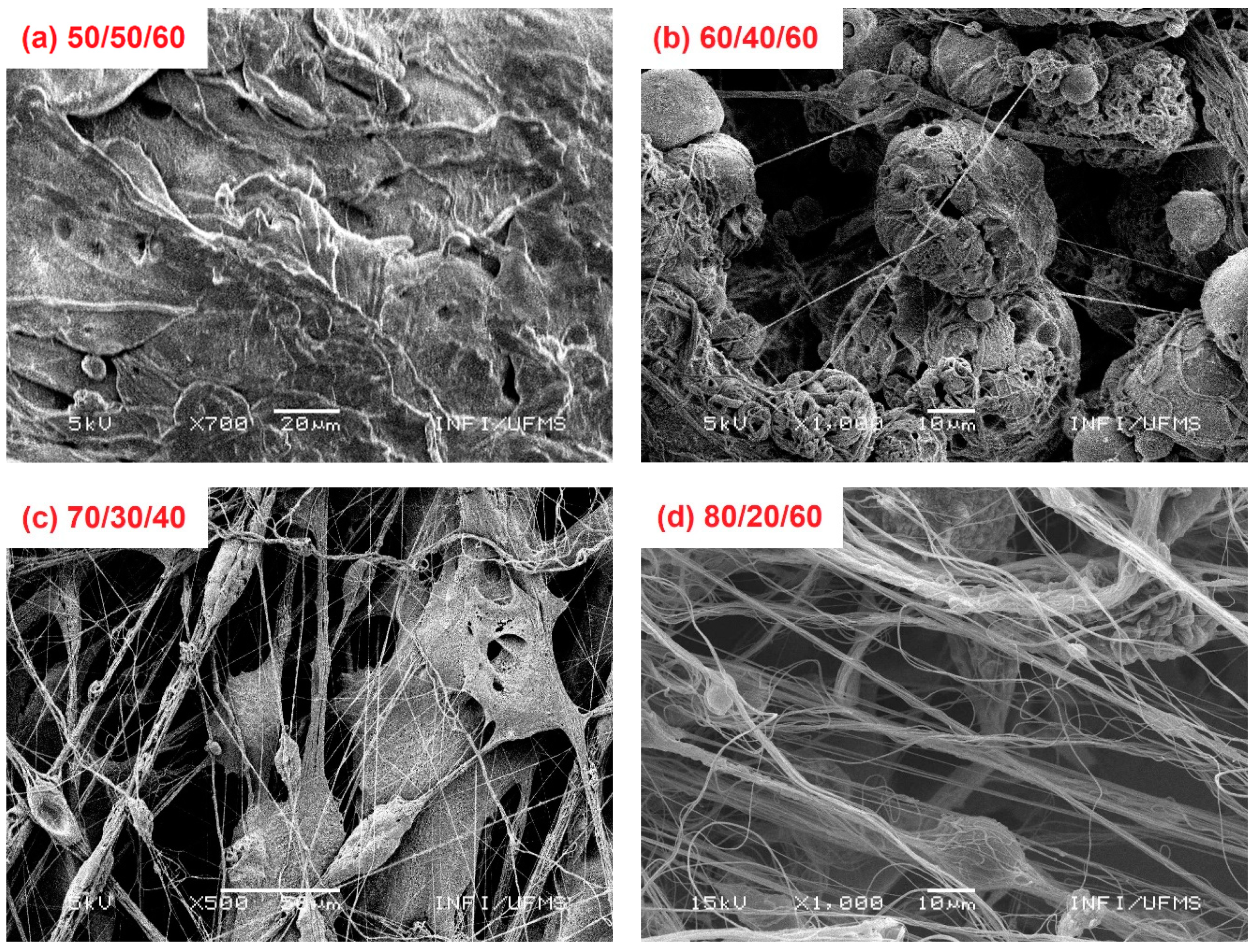
The samples produced with highly volatile solution, by introducing acetone above 20% in volume, Figure 2a–c, did not show a pure fiber formation. Figure 2a shows two different classic formations, the first not homogenous. Thick and flattened fiber formation can be observed because the solvent volatility and drag forces can pull fibers from the tip, but the high solvent volatility causes the uneven ejection of more material. In the second, entire drops are ejected from the tip and the exploded drop morphology is also observed on the fiber mat.
In Figure 2b, smooth, uniform, and thin fiber formation are observed in low amounts, but several entire drops were obtained. The air flux causes fast solvent evaporation, then entire dry drops can be ejected from the tip, and several defects in the fiber mat increase; similar behavior has been reported in the literature [14]. By adjusting the solution volatility, the fiber formation started (Figure 2c) but nonetheless a lot of defects were observed due to the entire drop ejection from the tip, following which exploded drop formation could be observed. Finally, smooth and uniform fiber formation was obtained after fine adjustments in the experimental parameters (gas pressure, injection rate, work distance) improving the fiber quality (Figure 2d).
Figure 3 shows SEM images and histograms of the obtained sub-microfibers produced from pure PVDF and PVDF/KNO3 solution. The respective histograms showed a monomodal distribution, with 285 nm and 370 nm fiber average diameter. PVDF sub-microfibers showed a smooth and continuous morphology (Figure 3a). The introduction of KNO3 into the solution may promote the alteration of the solution’s rheological properties. As a result, we can observe a high concentration of bead formation in the mat (yellow circle), Figure 3b.
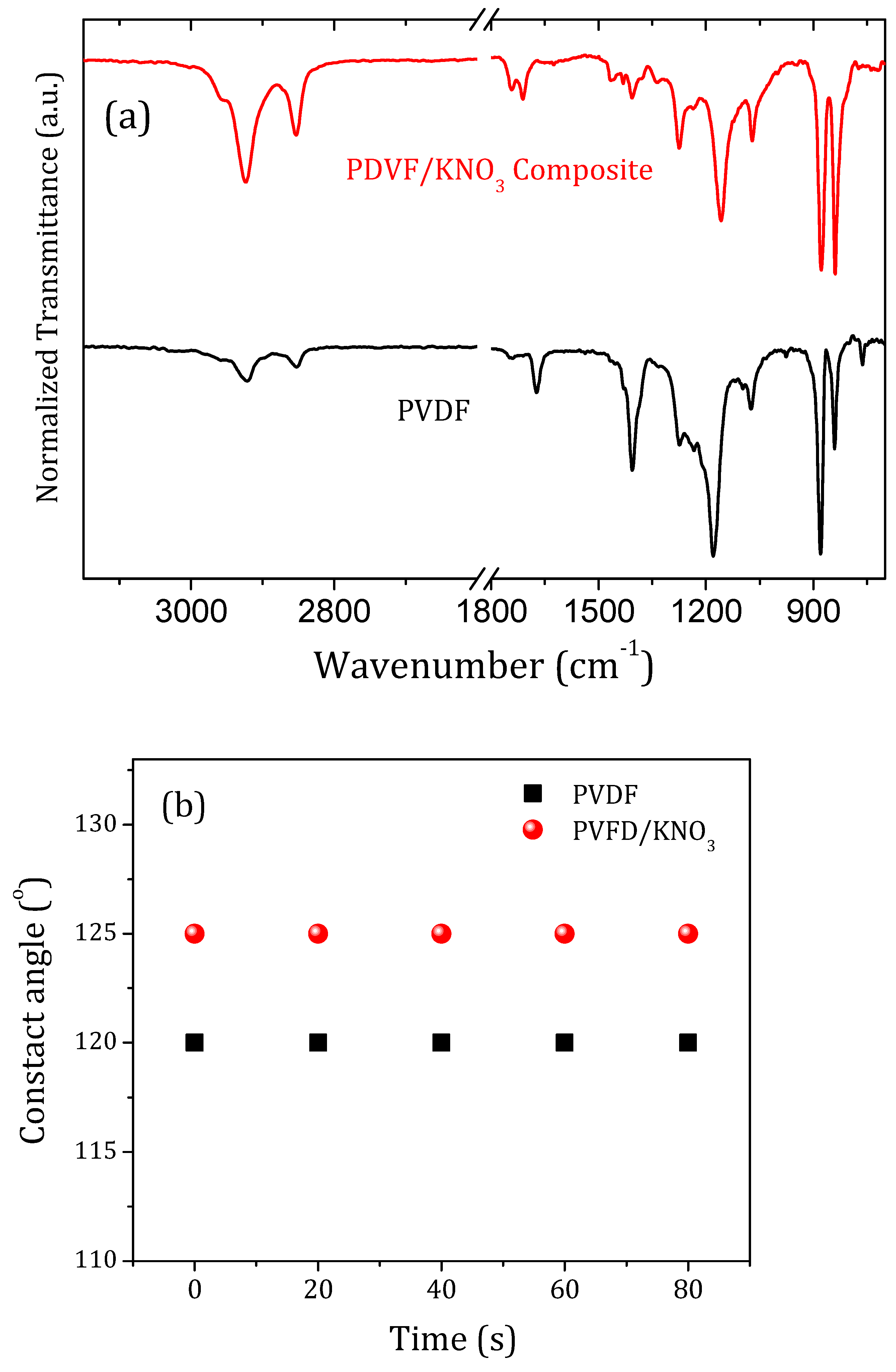
The thermal degradation for both samples starts only above 370 °C, which does not influence the desirable process for this type of application (Supplementary Materials, Figure S1). The FTIR spectra for PVDF and PVDF/KNO3 sub-microfibers are presented in Figure 4a. Dissimilar bands are evidenced between 1800 cm−1 and 1070 cm−1. This happens, probably, because of changes in the proportion of PVDF phases in the fibers promoted by introducing KNO3 in the solution. Nonetheless, the main band assigned to NO3 symmetric vibration around 1363 cm−1 was not evidenced [25]. Asymmetric axial deformation of CH2 (2923 and 2852 cm−1); axial deformation due to C=O (1739 and 1710 cm−1), followed by C=C (1672 cm−1); CH bending (1465 and 1432 cm−1); and a strong band at 1402 cm−1 assigned CH2 axial deformation was observed only in PVDF spectra. A wide vibrational band starts at 1272 cm−1 (C-C axial and angular deformation) and goes until 1157 cm−1 in PVDF fibers assigned to C-N and CF2 vibration, and appears more detailed for PVDF/KNO3. Finally, we observe the CF2 angular deformation bands (1070, 872, and 760 cm−1) with CH2 angular deformation (838 cm−1) are quite different for both samples [23,24].
PVDF is a polymer with extremely low surface energy, which guarantees high contact angles observed in Figure 4b, demonstrating its hydrophobicity [26,27]. The contact angles of PVDF and PVDF/KNO3 were approximately 120° and 125°, respectively, and they did not change over time. Usually, in practice, a dynamic phenomenon of contact angle hysteresis is often observed because the liquid start to evaporate and should maintain the contact area, but there are two pure modes of evaporation of liquid drops on surfaces, one at the constant contact area and one at constant contact angle [28].
The release test performed for PVDF/KNO3 sub-microfibers is shown in Figure 5. The release mechanism for swellable polymeric matrices is a complex phenomenon. The mechanism can be classified as purely diffusion or erosion, or by the combination of both. Fick’s equation is the most common law to describe the model, in which the exponent “n” indicates the release mechanism (n ≤ 0.45 for diffusion-controlled mechanism—case I; n = 0.89 for case II, a relaxational release; non-Fickian, zero-order, is found for n > 0.89—values between 0.45 and 0.89 can be assigned to both phenomena) [29,30,31]. The release mechanism found for PVDF/KNO3 sub-microfibers does not obey Fick’s law, as demonstrated in Figure 5 by the orange dashed line, with an R2 of 0.82 and n parameter of 0.34. Other models were also tested such as Korsmeyer–Peppas and Higuchi, but failed to fit the data [30,31]. The best fit was obtained for our results by the empirical exponential equation y = e a + b x + c , with R2 of 0.92, whose terms had no specific meaning. We add a Langmuir fit, with an R2 of 0.93, just to explore the form of an equation that can perhaps better describe the data.
Our attempt to describe the model was unsuccessful, suggesting the anomalous behavior of our polymeric fibrous mat for fertilizer delivery. The data show a prominent release at the first 48 h. Subsequently, the release continues almost stably, which is very interesting but does not solve completely the problem for polymeric matrix delivery systems. The ideal way would be to observe a smaller delivery for 48 h. However, it is good enough in comparison with current models of direct fertilizing application in the soil that reach a leaching loss of almost 100% in the first 24 h.

4. Conclusions

PVDF/KNO3 sub-microfibers were successfully obtained by solution blow spinning, exhibiting many beads. The composite fiber mats showed a considerable difference in FTIR spectra, probably related to changes in the proportions between the different phases exhibited by the PVDF polymeric chain. The hydrophobic nature of the material was preserved by adding KNO3 into the matrix. Kinetic release tests reveal that PVDF/KNO3 sub-microfibers do not obey Fick’s law. Nonetheless, their release behavior cannot avoid the fertilizer delivery in the first 48 h, before the seed germination. New studies of composite and blend matrices can drive us to interesting delivery systems for agriculture.

Supplementary Materials

The following supporting information can be downloaded at: https://www.mdpi.com/article/10.3390/polym14051000/s1, Figure S1: Thermogravimetric analysis (TGA), under nitrogen atmosphere with 60 mL/min steady flow, from room temperature up to 800 °C to evaluate the thermal stability of the samples.

Author Contributions

Conceptualization, C.C.; methodology, F.S. and T.C.; validation, A.-M.G.; formal analysis, C.C. and M.J.S.; investigation, F.S.; data curation, A.-M.G. and C.C.; writing—original draft preparation, C.C.; writing—review and editing, C.C. and A.-M.G.; supervision, C.C. and A.-M.G.; project administration, C.C.; funding acquisition, C.C. All authors have read and agreed to the published version of the manuscript.

Funding

Conselho Nacional de Desenvolvimento Científico e Tecnológico (CNPq), grant number: 408127/2018-0. The authors also thank to Coordenação de Aperfeiçoamento de Pessoal de Nível Superior—Brasil (CAPES)—Finance Code 001.

Data Availability Statement

Data available on request.

Acknowledgments

This study was financed by Conselho Nacional de Desenvolvimento Científico e Tecnológico (CNPq), grant number: 408127/2018-0. The authors also thank to Coordenação de Aperfeiçoamento de Pessoal de Nível Superior—Brasil (CAPES)—Finance Code 001.

Conflicts of Interest

The authors declare no conflict of interest.

References

  1. Milani, P.; França, D.; Balieiro, A.G.; Faez, R. Polymers and its applications in agriculture. Polímeros 2017, 27, 256–266. [Google Scholar] [CrossRef]
  2. Bansal, P. Water-Based Polymeric Nanostructures for Agricultural Applications. Ph.D. Thesis, Philipps-Universitat Marburg, Marbug, Germanny, 2010. [Google Scholar]
  3. Bisotto-de-Oliveira, R.; Jorge, B.C.; Roggia, I.; Santana, J.; Pereira, C.N. Nanofibers as a vehicle for the synthetic attactant trimedlure to be used for ceratitis capitata wied: (Díptera, tethritidae) capture. J. Res. Updates Polym. Sci. 2014, 3, 40–47. [Google Scholar] [CrossRef]
  4. Bisotto-de-Oliveira, R.; Morais, R.M.; Roggia, I.; Silva, S.J.N.; Santana, J.; Pereira, C.N. Polymers nanofibers as vehicles for the release of the synthetic sex pheromone of grapholita molesta. Rev. Colomb. Entomol. 2015, 41, 2. [Google Scholar]
  5. Castenada, L.M.F.; Genro, C.; Roggia, I.; Bender, S.S.; Bender, R.J.; Pereira, C.N. Innovative rice seed coating (Oryza sativa) with polymer nanofibers and microparticles using the electrospinning method. J. Res. Updates Polym. Sci. 2014, 3, 33–39. [Google Scholar]
  6. Damasceno, R.; Roggia, I.; Pereira, C.; SÁ, E. Rhizobia survival in seeds coated with PVA Electrospun nanofibers. Can. J. Microbiol. 2013, 59, 716–719. [Google Scholar] [CrossRef]
  7. Gregorio, P.R.; Michavilla, G.; Muller, L.R.; Borges, C.S.; Pomares, M.F.; Sá, E.L.S.; Pereira, C.; Vincent, P.A. Beneficial rhizobacteria immobilized in nanofibers for potential applications as soybean seed bioinoculants. PLoS ONE 2017, 4, e0176930. [Google Scholar] [CrossRef] [Green Version]
  8. Castro-Enríquez, D.D.; Rodríguez-Félix, F.; Ramírez-Wong, B.; Torres-Chávez, P.I.; Castillo-Ortega, M.M.; Rodríguez-Félix, D.E.; Armenta-Villegas, L.; Ledesma-Osuna, A.I. Preparation, Characterization and Release of Urea from Wheat Gluten Electrospun Membranes. Materials 2012, 5, 2903–2916. [Google Scholar] [CrossRef] [Green Version]
  9. Kampeerapappun, P.; Phanomkate, N. Slow release fertilizer from core-shell Electrospun fibers. Chiang Mai J. Sci. 2013, 40, 4. [Google Scholar]
  10. Krishnamoorthy, V.; Rajiv, S. An eco-friendly top-down approach to nutrient incorporated Electrospun seed coating for superior germination potential. J. Adv. App. Sci. Res. 2017, 1, 7. [Google Scholar]
  11. Palvannan, T.; Saravanakumar, T.; Unnithan, A.R.; Chung, N.J.; Kim, D.H.; Park, S.M. Efficient transformation of phenyl urea herbicide chloroxuron by laccase immobilized on zein polyurethane nanofiber. J. Mol. Catal. B 2014, 99, 3. [Google Scholar] [CrossRef]
  12. Pule, B.O.; Degni, S.; Torto, N. Electrospun fiber colorimetric probe based on gold nanoparticles for on-site detection of estradiol associated with dairy farming effluents. Afr. J. Online 2015, 41, 27–32. [Google Scholar]
  13. Bhardwaj, N.; Kundu, S.C. Electrospinning: A fascinating fibers fabrication technique. Biotechnol. Adv. Oxf. 2010, 28, 325–347. [Google Scholar] [CrossRef] [PubMed]
  14. Cena, C.R.; Silva, M.J.; Malmonge, L.F.; Malmonge, J.A. Poly(vinyl pyrrolidone) sub-microfibers produced by solution blow spinning. J. Polym. Res. 2018, 25, 238. [Google Scholar] [CrossRef]
  15. Cena, C.R.; Larios, G.S.; Bica, M.R.R.; Canassa, T.A.; Freitas, G.Q.; Torsoni, G.B. Desenvolvimento de um sistema Blow-Spinning de baixo custo: Obtenção de microfibras e nanofibras poliméricas e compósitas. Rev. Bras. Física Tecnol. Apl. 2015, 2, 32–44. [Google Scholar] [CrossRef]
  16. Viana, J.L.; França, T.; Larios, G.S.; Cena, C. Solution Blow Spinning Poly(vinyl alcohol) Sub-microfibers Produced from Different Solvents. Orbital Electron. J. Chem. 2020, 12, 120036. [Google Scholar] [CrossRef]
  17. Cena, C.R.; Torsoni, G.B.; Zadorosny, L.; Malmonge, L.F.; Carvalho, C.L.; Malmonge, J.A. BSCCO superconductor micro/nanofibers produced by solution blow-spinning technique. Ceram. Int. 2017, 43, 7663–7667. [Google Scholar] [CrossRef] [Green Version]
  18. Cena, C.R.; Behera, A.K.; Behera, B. Structural, dielectric, and electrical properties of lithium niobate microfibers. J. Adv. Ceram. 2016, 5, 84–92. [Google Scholar] [CrossRef] [Green Version]
  19. Gasparini, T.M.; Bretas, R.E.S.; da Silva, A.B.; Rinaldo, G., Jr. Processing and characterization of oriented electrospun poly(vinylidene fluoride) mats. J. Polym. Sci. Part B Polym. Phys. 2012, 50, 1304–1311. [Google Scholar] [CrossRef]
  20. Gregorio, R.; Borges, D.S. Effect of crystallization rate on the formation of the polymorphs of solution cast poly(vinylidene fluoride). J. Polym. 2008, 49, 4009–4016. [Google Scholar] [CrossRef]
  21. Costa, L.M.M.; Bretas, R.E.S.; Filho, R.G. Caracterização de filmes de PVDF-β obtidos por diferentes técnicas. Polímeros 2009, 19, 183–189. [Google Scholar] [CrossRef] [Green Version]
  22. Jang, W.; Yun, J.; Jeon, K.; Byun, H. PVdF/graphene oxide hybrid membranes via electrospinning for water treatment applications. RSC Adv. 2015, 5, 46711–46717. [Google Scholar] [CrossRef]
  23. Larios, G.S.; Nogueira, F.S.; Viana, J.L.; Oliveira, R.H.; Ferreira, D.C.; Ilha, V.N.; Canassa, T.A.; Plaça, L.F. Síntese e Caracterização de Sub-microfibras de PVDF/GO via Blow-Spinning. J. Exp. Tech. Instrum. 2018, 1, 1–8. [Google Scholar] [CrossRef]
  24. Dias, G.C.; Cellet, T.S.P.; Santos, M.C.; Sanches, A.; Malmonge, L.F. PVDF nanofibers obtained by solution blow spinning with use of a commercial airbrush. J. Polym. Res. 2019, 26, 87. [Google Scholar] [CrossRef]
  25. Messa, L.; Froes, J.D.; Souza, C.; Faez, R. Híbridos de quitosana-argila para encapsulamento e liberação sustentada do fertilizante nitrato de potássio. Química Nova 2016, 39, 1215–1220. [Google Scholar] [CrossRef]
  26. Kamaz, M.; Sengupta, A.; Gutierrez, A.; Chiao, Y.H.; Wickramasinghe, R. Surface modification of PVDF membranes for treating produced Waters by direct contact membrane distillation. Int. J. Environ. Res. Public Health 2019, 16, 685. [Google Scholar] [CrossRef] [Green Version]
  27. Kaynak, A.; Mehmood, T.; Dai, X.J.; Magniez, K.; Kouzani, A. Study of Radio Frequency Plasma Treatment of PVDF Film Using Ar, O2 and (Ar + O2) Gases for Improved Polypyrrole Adhesion. Materials 2013, 6, 3482–3493. [Google Scholar] [CrossRef] [Green Version]
  28. Erbil, H.Y.; Mchale, G.; Newton, M.I. Drop evaporation on solid surfaces: Constant contact angle mode. Langmuir 2002, 18, 2636–2641. [Google Scholar] [CrossRef]
  29. Arora, G.; Malik, K.; Singh, I. Formulation and evaluation of mucoadhesive matrix tablets of taro gum: Optimization using response surface methodology. Polim. Med. 2011, 41, 23–34. [Google Scholar]
  30. Siepmann, J.; Peppas, N.A. Higuchi equation: Derivation, applications, use and misuse. Int. J. Pharm. 2011, 418, 6–12. [Google Scholar] [CrossRef]
  31. Permanadewi, I.; Kumoro, A.C.; Wardhani, D.H.; Aryanti, M. Modelling of controlled drug release in gastrointestinal tract simulation. J. Phys. 2019, 1295, 012063. [Google Scholar] [CrossRef]
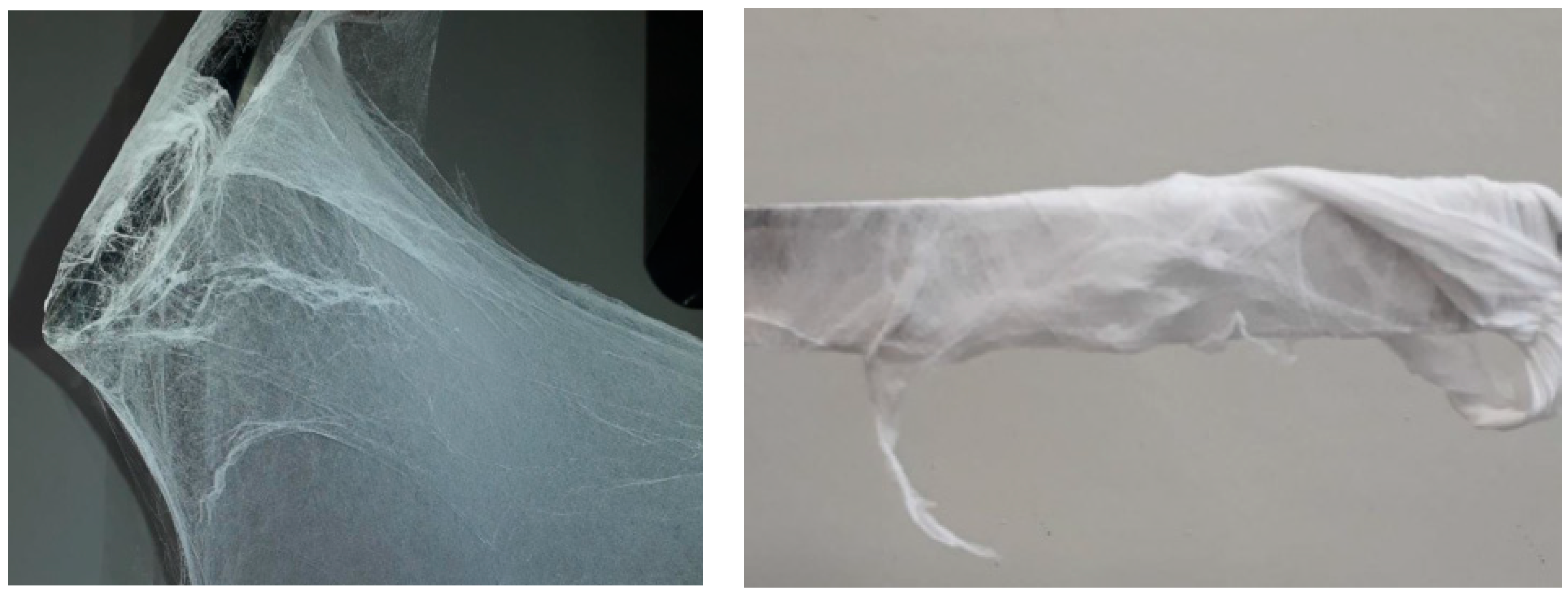
Figure 1. PVDF sub-microfiber mat produced by solution blow spinning.
Polymers 14 01000 g001
Figure 2. Sample formation for different experimental conditions. (a) DMF/acetone = 50/50, gas pressure 60 Psi; (b) DMF/acetone = 60/40, gas pressure 60 Psi; (c) DMF/acetone = 70/30, gas pressure 40 Psi; (d) DMF/acetone = 80/20, gas pressure 60 Psi.
Polymers 14 01000 g002
Figure 3. SEM image (a) of PVDF fibers (0.1 g/mL) and (b) PVDF/KNO3 fibers; (c,d) are the respective histograms, with average diameter values around 285 nm and 370 nm, respectively. The bead formation is evidenced by the round yellow mark in (b).
Polymers 14 01000 g003
Figure 4. (a) FTIR spectra and (b) contact angle for PDVF and PVDF/KNO3 sub-microfibers.
Polymers 14 01000 g004
Figure 5. Water conductivity curve as a function of time for PVDF/KNO3 sub-microfiber release kinetic study.
Polymers 14 01000 g005
Publisher’s Note: MDPI stays neutral with regard to jurisdictional claims in published maps and institutional affiliations.