
Physicochemical Modifications on Thin Films of Poly(Ethylene Terephthalate) and Its Nanocomposite with Expanded Graphite Nanostructured by Ultraviolet and Infrared Femtosecond Laser Irradiation

 , , ,
, , , 
Abstract
1. Introduction
2. Materials and Methods
2.1. Materials
2.2. Laser Irradiation
2.3. Characterization
3. Results
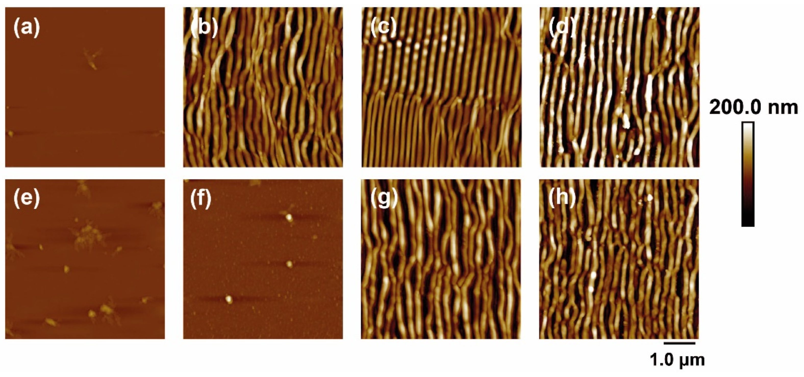
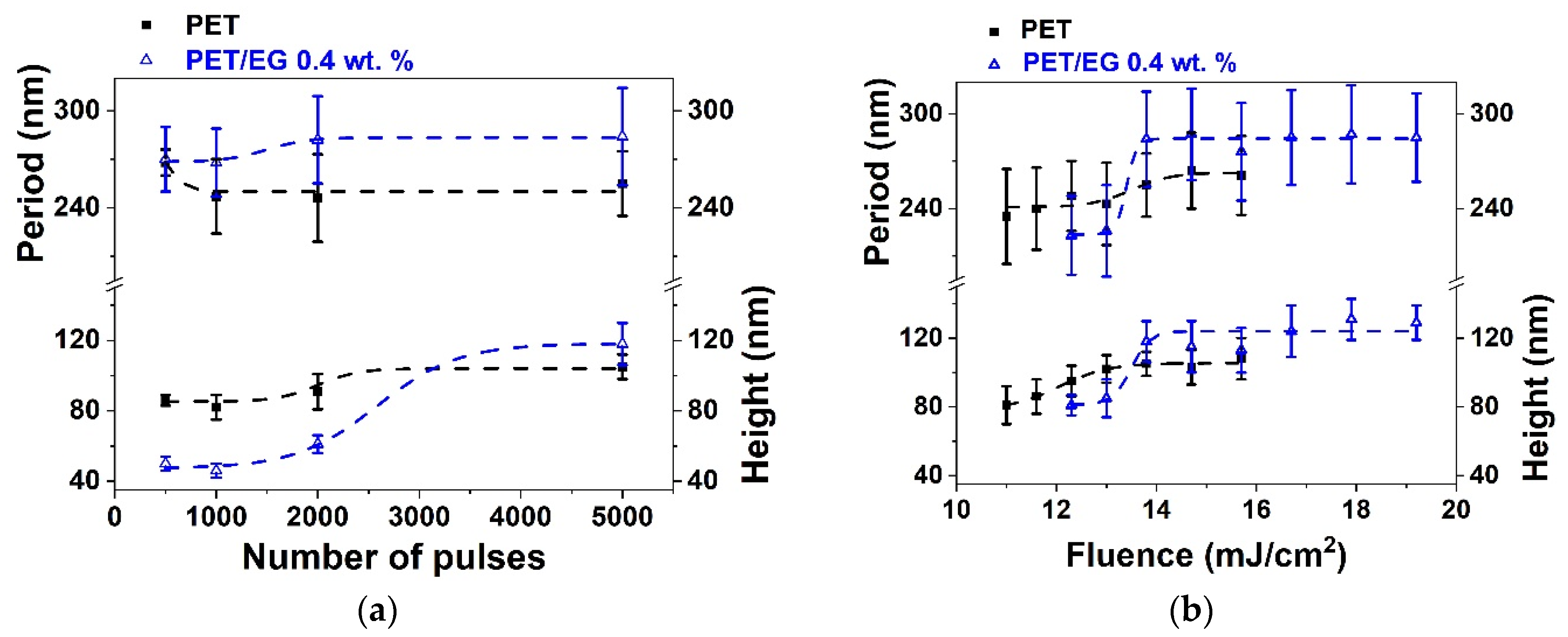
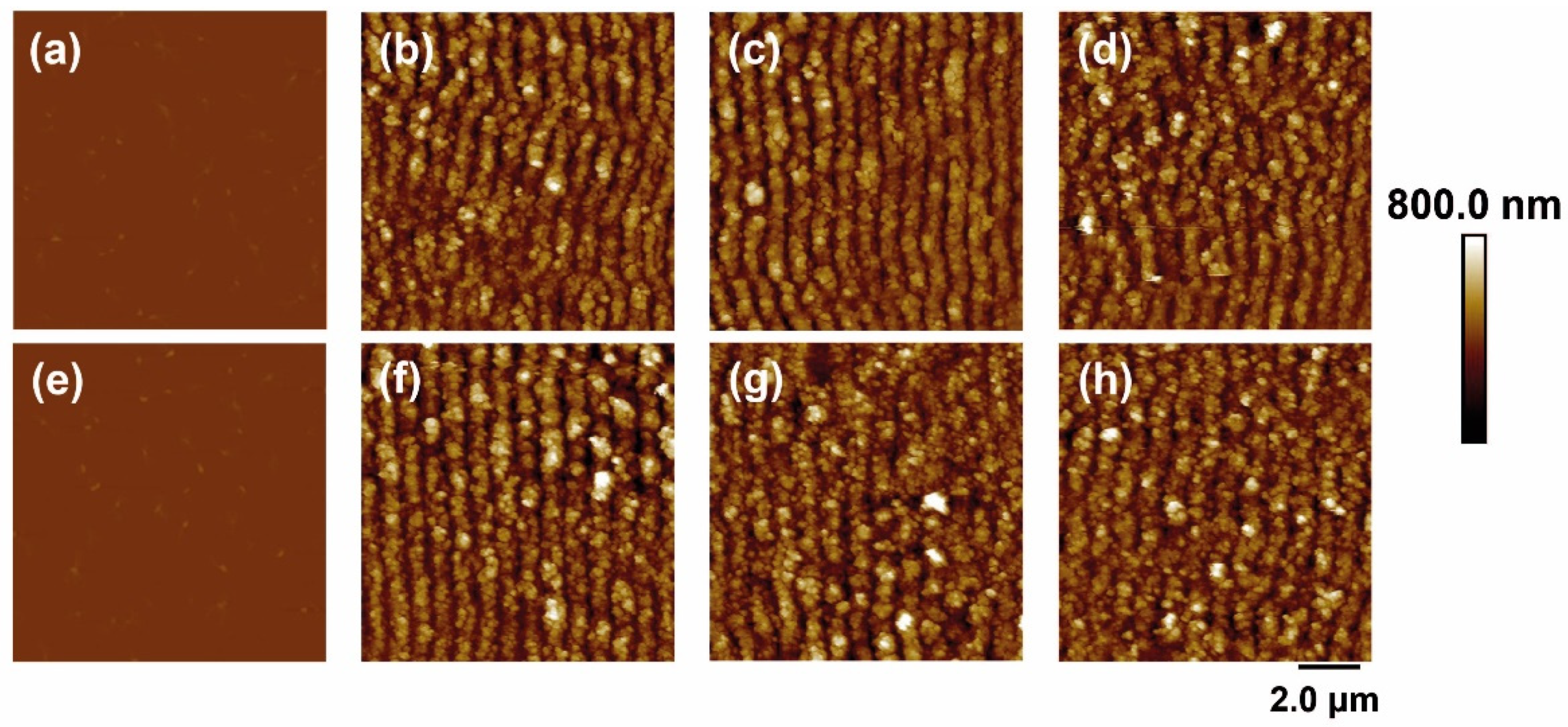
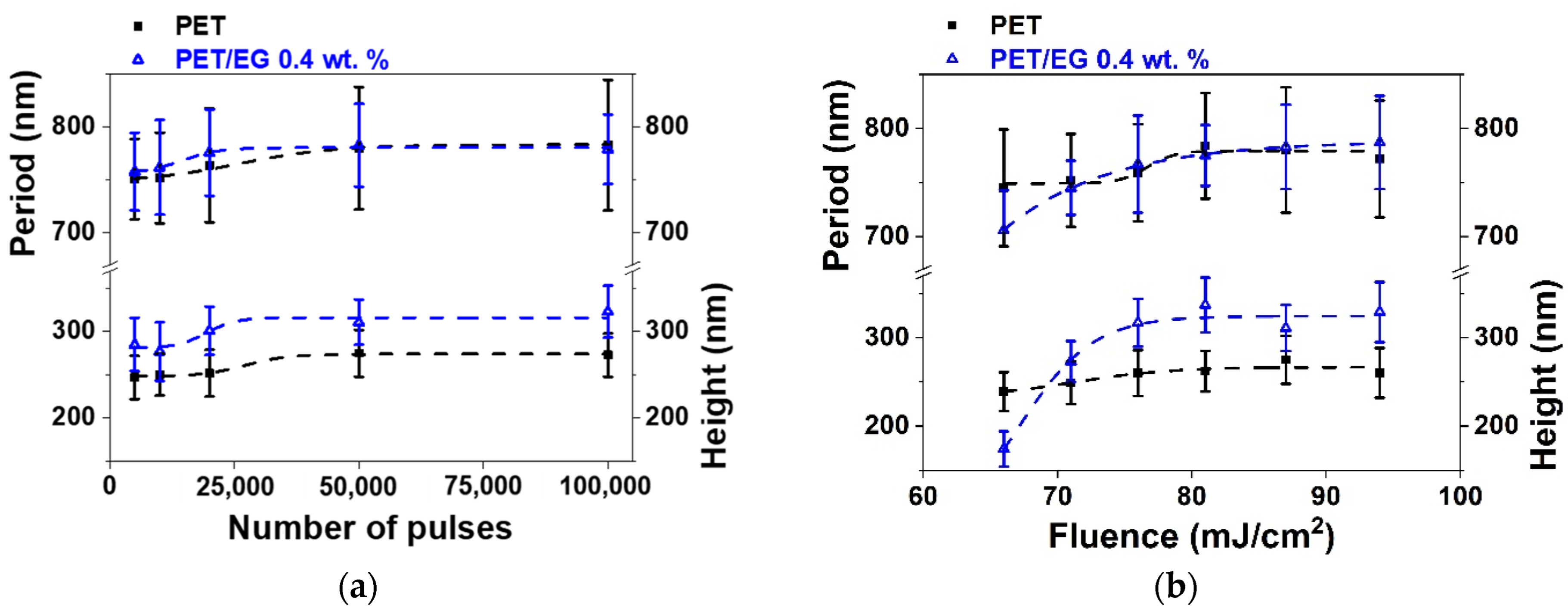
3.1. LIPSS Formation
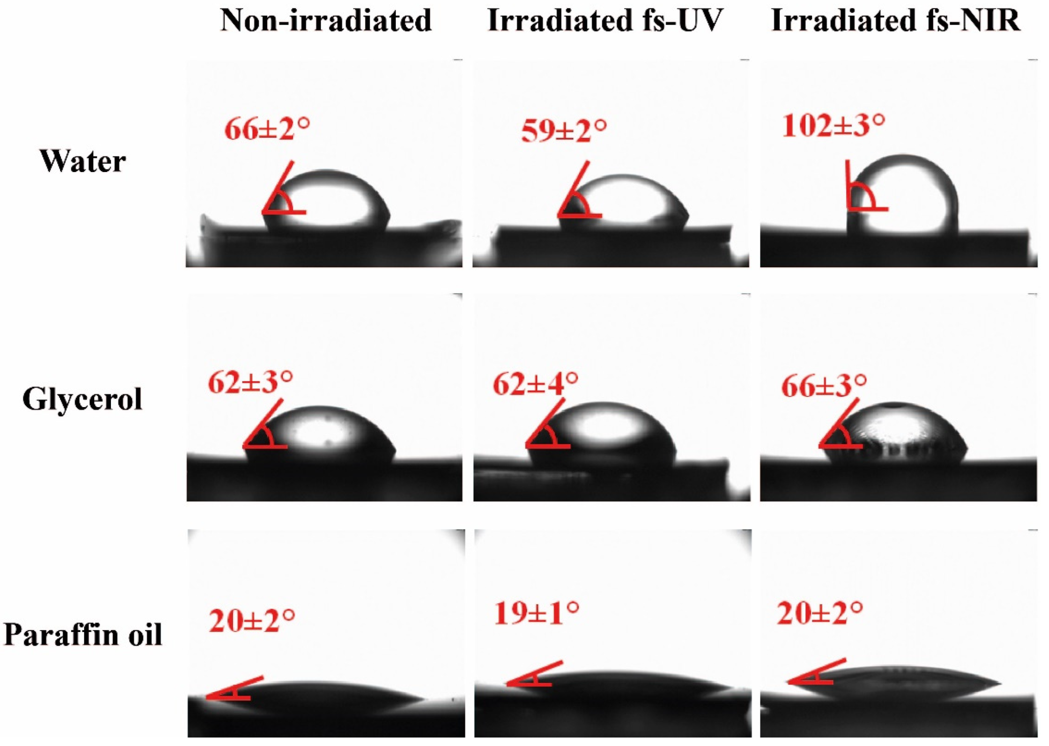
3.2. Determination of Contact Angles for Different Test Liquids
3.3. Surface Free Energy
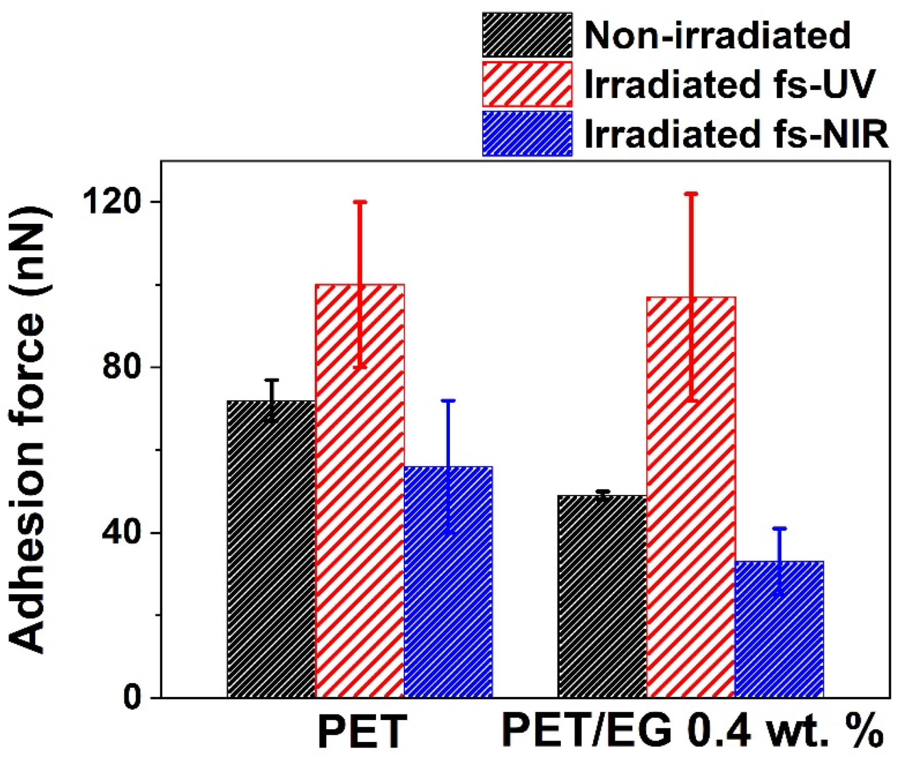
3.4. Modification of Adhesion Force
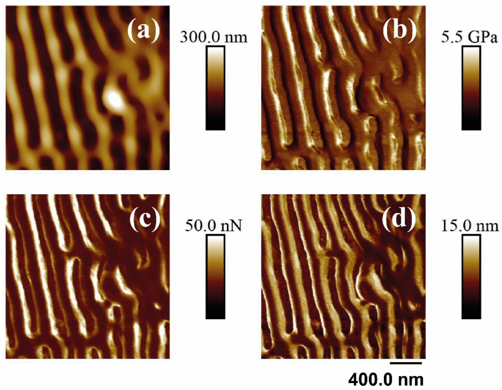
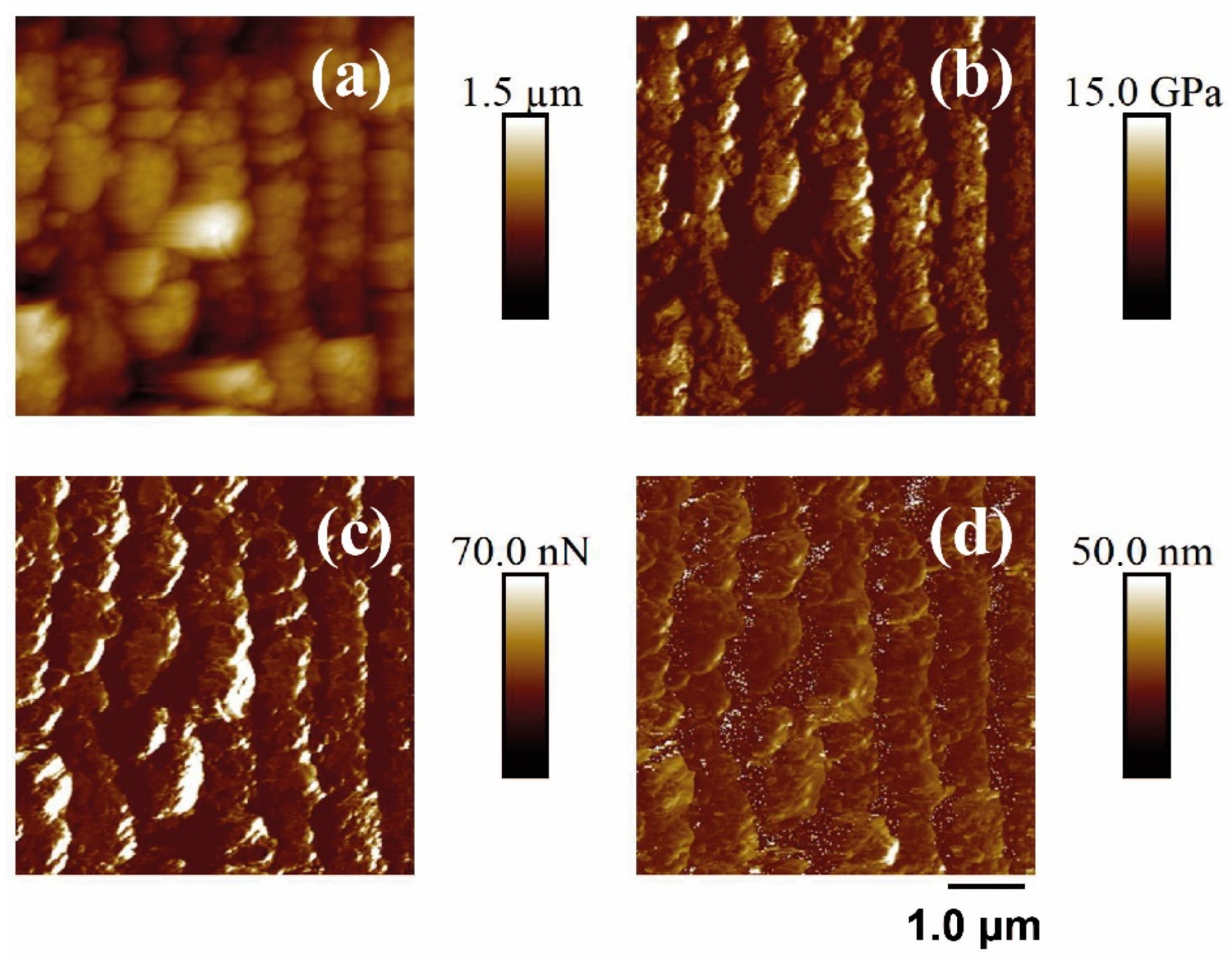
3.5. Nanomechanical Properties
4. Conclusions
Supplementary Materials
Author Contributions
Funding
Institutional Review Board Statement
Data Availability Statement
Acknowledgments
Conflicts of Interest
References
- Namazi, H. Polymers in our daily life. BioImpacts BI 2017, 7, 73. [Google Scholar] [CrossRef] [PubMed]
- Peplow, M. The plastics revolution: How chemists are pushing polymers to new limits. Nature 2016, 536, 266–268. [Google Scholar] [CrossRef] [PubMed]
- Cowie, J.M.G.; Arrighi, V. Polymers: Chemistry and Physics of Modern Materials; CRC Press: Boca Raton, FL, USA, 2007; ISBN 0429125542. [Google Scholar]
- Paszkiewicz, S.; Szymczyk, A.; Pilawka, R.; Przybyszewski, B.; Czulak, A.; RosŁaniec, Z. Improved Thermal Conductivity of Poly(trimethylene terephthalate-block-poly(tetramethylene oxide) Based Nanocomposites Containing Hybrid Single-Walled Carbon Nanotubes/Graphene Nanoplatelets Fillers. Adv. Polym. Technol. 2017, 36, 236–242. [Google Scholar] [CrossRef]
- Mittal, G.; Dhand, V.; Rhee, K.Y.; Park, S.-J.; Lee, W.R. A review on carbon nanotubes and graphene as fillers in reinforced polymer nanocomposites. J. Ind. Eng. Chem. 2015, 21, 11–25. [Google Scholar] [CrossRef]
- Paszkiewicz, S.; Szymczyk, A.; Livanov, K.; Wagner, H.D.; Rosłaniec, Z. Enhanced thermal and mechanical properties of poly (trimethylene terephthalate-block-poly (tetramethylene oxide) segmented copolymer based hybrid nanocomposites prepared by in situ polymerization via synergy effect between SWCNTs and graphene nanoplatelet. Express Polym. Lett. 2015, 9, 509–524. [Google Scholar] [CrossRef]
- Hu, K.; Kulkarni, D.D.; Choi, I.; Tsukruk, V. V Graphene-polymer nanocomposites for structural and functional applications. Prog. Polym. Sci. 2014, 39, 1934–1972. [Google Scholar] [CrossRef]
- Paszkiewicz, S.; Taraghi, I.; Szymczyk, A.; Huczko, A.; Kurcz, M.; Przybyszewski, B.; Stanik, R.; Linares, A.; Ezquerra, T.A.; Rosłaniec, Z. Electrically and thermally conductive thin elastic polymer foils containing SiC nanofibers. Compos. Sci. Technol. 2017, 146, 20–25. [Google Scholar] [CrossRef]
- Tao, Z.; Wang, H.; Li, X.; Liu, Z.; Guo, Q. Expanded graphite/polydimethylsiloxane composites with high thermal conductivity. J. Appl. Polym. Sci. 2017, 134, 44843. [Google Scholar] [CrossRef]
- Paszkiewicz, S.; Kochmański, P.; Kochmańska, A.; Fryczkowski, R.; Sieradzka, M.; Bartkowiak, A.; Lisiecki, S.; Jotko, M.; Piesowicz, E.; Irska, I. Improvement of barrier properties of glycol modified poly (ethylene terephthalate) based nanocomposites containing graphene derivatives forms. Polimery 2017, 62, 868–874. [Google Scholar] [CrossRef]
- Celzard, A.; Marêché, J.F.; Furdin, G. Modelling of exfoliated graphite. Prog. Mater. Sci. 2005, 50, 93–179. [Google Scholar] [CrossRef]
- Goyal, R.K.; Jagadale, P.A.; Mulik, U.P. Thermal, mechanical, and dielectric properties of polystyrene/expanded graphite nanocomposites. J. Appl. Polym. Sci. 2009, 111, 2071–2077. [Google Scholar] [CrossRef]
- Zhang, M.; Li, D.-J.; Wu, D.-F.; Yan, C.-H.; Lu, P.; Qiu, G.-M. Poly(ethylene terephthalate)/expanded graphite conductive composites: Structure, properties, and transport behavior. J. Appl. Polym. Sci. 2008, 108, 1482–1489. [Google Scholar] [CrossRef]
- Paszkiewicz, S.; Pawelec, I.; Szymczyk, A.; Špitalský, Z.; Mosnáček, J.; Kochmańska, A.; Rosłaniec, Z. Effect of exfoliated graphite nanoplatelets’ size on the phase structure, electrical, and barrier properties of poly(trimethylene terephthalate)-based nanocomposites. Polym. Eng. Sci. 2015, 55, 2222–2230. [Google Scholar] [CrossRef]
- Firkowska-Boden, I.; Zhang, X.; Jandt, K.D. Controlling Protein Adsorption through Nanostructured Polymeric Surfaces. Adv. Healthc. Mater. 2018, 7, 1700995. [Google Scholar] [CrossRef] [PubMed]
- Arango, J.C.; Williams, L.O.; Shi, A.; Singh, A.; Nava, E.K.; Fisher, R.V.; Garfield, J.A.; Claridge, S.A. Nanostructured Surface Functionalization of Polyacrylamide Hydrogels Below the Length Scale of Hydrogel Heterogeneity. ACS Appl. Mater. Interfaces 2022, 14, 43937–43945. [Google Scholar] [CrossRef]
- Schutzius, T.M.; Jung, S.; Maitra, T.; Eberle, P.; Antonini, C.; Stamatopoulos, C.; Poulikakos, D. Physics of Icing and Rational Design of Surfaces with Extraordinary Icephobicity. Langmuir 2015, 31, 4807–4821. [Google Scholar] [CrossRef]
- White, B.; Sarkar, A.; Kietzig, A.-M. Fog-harvesting inspired by the Stenocara beetle—An analysis of drop collection and removal from biomimetic samples with wetting contrast. Appl. Surf. Sci. 2013, 284, 826–836. [Google Scholar] [CrossRef]
- Hu, D.; Yu, Q.; Yang, Y.; Weng, L. Fabrication and wetting behaviour of micro/nanostructured mushroom-shaped silver pillar surface. Nanotechnology 2020, 31, 175701. [Google Scholar] [CrossRef]
- El-Saftawy, A.A.; Elfalaky, A.; Ragheb, M.S.; Zakhary, S.G. Electron beam induced surface modifications of PET film. Radiat. Phys. Chem. 2014, 102, 96–102. [Google Scholar] [CrossRef]
- Kormunda, M.; Pavlik, J. Characterization of oxygen and argon ion flux interaction with PET surfaces by in-situ XPS and ex-situ FTIR. Polym. Degrad. Stab. 2010, 95, 1783–1788. [Google Scholar] [CrossRef]
- Mui, T.S.M.; Mota, R.P.; Quade, A.; Hein, L.R.D.O.; Kostov, K.G. Uniform surface modification of polyethylene terephthalate (PET) by atmospheric pressure plasma jet with a horn-like nozzle. Surf. Coat. Technol. 2018, 352, 338–347. [Google Scholar] [CrossRef]
- Schift, H. Nanoimprint lithography: An old story in modern times? A review. J. Vac. Sci. Technol. B Microelectron. Nanometer Struct. Process. Meas. Phenom. 2008, 26, 458. [Google Scholar] [CrossRef]
- Rebollar, E.; Castillejo, M.; Ezquerra, T.A. Laser induced periodic surface structures on polymer films: From fundamentals to applications. Eur. Polym. J. 2015, 73, 162–174. [Google Scholar] [CrossRef]
- Bonse, J.; Gräf, S. Ten open questions about laser-induced periodic surface structures. Nanomaterials 2021, 11, 3326. [Google Scholar] [CrossRef]
- Bonse, J.; Kirner, S.V.; Krüger, J. Laser-induced periodic surface structures (LIPSS). In Handbook of Laser Micro-and Nano-Engineering; Springer: Berlin/Heidelberg, Germany, 2021; pp. 1–59. [Google Scholar] [CrossRef]
- Martín-Fabiani, I.; Rebollar, E.; Pérez, S.; Rueda, D.R.; García-Gutiérrez, M.C.; Szymczyk, A.; Roslaniec, Z.; Castillejo, M.; Ezquerra, T.A. Laser-induced periodic surface structures nanofabricated on poly(trimethylene terephthalate) spin-coated films. Langmuir 2012, 28, 7938–7945. [Google Scholar] [CrossRef] [PubMed]
- Fajstavr, D.; Neznalová, K.; Švorčík, V.; Slepička, P. LIPSS Structures Induced on Graphene-Polystyrene Composite. Materials 2019, 12, 3460. [Google Scholar] [CrossRef]
- Mezera, M.; van Drongelen, M.; Römer, G.R.B.E. Laser-Induced Periodic Surface Structures (LIPSS) on Polymers Processed with Picosecond Laser Pulses. J. Laser Micro/Nanoeng. 2018, 13, 105–116. [Google Scholar] [CrossRef]
- Mezera, M.; Bonse, J.; Römer, G.R.B.E. Influence of Bulk Temperature on Laser-Induced Periodic Surface Structures on Polycarbonate. Polymers 2019, 11, 1947. [Google Scholar] [CrossRef]
- Shavdina, O.; Rabat, H.; Vayer, M.; Petit, A.; Sinturel, C.; Semmar, N. Polystyrene Thin Films Nanostructuring by UV Femtosecond Laser Beam: From One Spot to Large Surface. Nanomaterials 2021, 11, 1060. [Google Scholar] [CrossRef]
- Rebollar, E.; Vázquez de Aldana, J.R.; Pérez-Hernández, J.A.; Ezquerra, T.A.; Moreno, P.; Castillejo, M. Ultraviolet and infrared femtosecond laser induced periodic surface structures on thin polymer films. Appl. Phys. Lett. 2012, 100, 041106. [Google Scholar] [CrossRef]
- Gräf, S. Formation of laser-induced periodic surface structures on different materials: Fundamentals, properties and applications. Adv. Opt. Technol. 2020, 9, 11–39. [Google Scholar] [CrossRef]
- Bonse, J.; Kirner, S.V.; Höhm, S.; Epperlein, N.; Spaltmann, D.; Rosenfeld, A.; Krüger, J.; Kirner, V.S.; Höhm, S.; Epperlein, N.; et al. Applications of laser-induced periodic surface structures (LIPSS). In Laser-Based Micro- and Nanoprocessing XI; Klotzbach, U., Washio, K., Kling, R., Eds.; SPIE: Bellingham, WA, USA, 2017; Volume 10092, pp. 114–122. [Google Scholar]
- Volpe, A.; Gaudiuso, C.; Ancona, A. Laser Fabrication of Anti-Icing Surfaces: A Review. Materials 2020, 13, 5692. [Google Scholar] [CrossRef] [PubMed]
- Sorgato, M.; Zanini, F.; Masato, D.; Lucchetta, G. Submicron laser-textured vents for self-cleaning injection molds. J. Appl. Polym. Sci. 2020, 137, 49280. [Google Scholar] [CrossRef]
- Hermens, U.; Kirner, S.V.; Emonts, C.; Comanns, P.; Skoulas, E.; Mimidis, A.; Mescheder, H.; Winands, K.; Krüger, J.; Stratakis, E.; et al. Mimicking lizard-like surface structures upon ultrashort laser pulse irradiation of inorganic materials. Appl. Surf. Sci. 2017, 418, 499–507. [Google Scholar] [CrossRef]
- Rodríguez-Beltrán, R.I.; Hernandez, M.; Paszkiewicz, S.; Szymczyk, A.; Rosłaniec, Z.; Ezquerra, T.A.; Castillejo, M.; Moreno, P.; Rebollar, E. Laser induced periodic surface structures formation by nanosecond laser irradiation of poly (ethylene terephthalate) reinforced with Expanded Graphite. Appl. Surf. Sci. 2018, 436, 1193–1199. [Google Scholar] [CrossRef]
- Paszkiewicz, S.; Szymczyk, A.; Špitalský, Z.; Soccio, M.; Mosnáček, J.; Ezquerra, T.A.; Rosłaniec, Z. Electrical conductivity of poly(ethylene terephthalate)/expanded graphite nanocomposites prepared by in situ polymerization. J. Polym. Sci. Part B Polym. Phys. 2012, 50, 1645–1652. [Google Scholar] [CrossRef]
- Good, R.J. Contact angle, wetting, and adhesion: A critical review. J. Adhes. Sci. Technol. 1992, 6, 1269–1302. [Google Scholar] [CrossRef]
- Sader, J.E.; Chon, J.W.M.; Mulvaney, P. Calibration of rectangular atomic force microscope cantilevers. Rev. Sci. Instrum. 1999, 70, 3967–3969. [Google Scholar] [CrossRef]
- Paszkiewicz, S.; Pawelec, I.; Szymczyk, A.; Rosłaniec, Z. Mechanical and thermal properties of hybrid nanocomposites prepared by in situ polymerization. Polimery 2016, 61, 172–180. [Google Scholar] [CrossRef]
- Kim, S.R.; Poostforush, M.; Kim, J.H.; Lee, S.G. Thermal diffusivity of in-situ exfoliated graphite intercalated compound/polyamide and graphite/polyamide composites. Express Polym. Lett. 2012, 6, 476–484. [Google Scholar] [CrossRef]
- Rebollar, E.; Rueda, D.R.; Martín-Fabiani, I.; Rodríguez-Rodríguez, Á.; García-Gutiérrez, M.-C.; Portale, G.; Castillejo, M.; Ezquerra, T.A. In situ monitoring of laser-induced periodic surface structures formation on polymer films by grazing incidence small-angle X-ray scattering. Langmuir 2015, 31, 3973–3981. [Google Scholar] [CrossRef] [PubMed]
- Koussi, E.-K.; Jung, H.J.; Faure, N.; Donnet, C.; Mauclair, C.; Sedao, X. Comparative Study of Ultraviolet and Infrared Femtosecond Laser Irradiation on Textile Polymers PET and PA66. J. Laser Micro/Nanoeng. 2020, 15, 245. [Google Scholar] [CrossRef]
- Wenzel, R.N. Resistance of solid surfaces to wetting by water. Ind. Eng. Chem. 1936, 28, 988–994. [Google Scholar] [CrossRef]
- Rebollar, E.; Pérez, S.; Hernández, M.; Domingo, C.; Martín, M.; Ezquerra, T.A.; García-Ruiz, J.P.; Castillejo, M. Physicochemical modifications accompanying UV laser induced surface structures on poly(ethylene terephthalate) and their effect on adhesion of mesenchymal cells. Phys. Chem. Chem. Phys. 2014, 16, 17551–17559. [Google Scholar] [CrossRef] [PubMed]
- Owens, D.K.; Wendt, R.C. Estimation of the surface free energy of polymers. J. Appl. Polym. Sci. 1969, 13, 1741–1747. [Google Scholar] [CrossRef]
- Sionkowska, A.; Kaczmarek, H.; Wisniewski, M.; Skopinska, J.; Lazare, S.; Tokarev, V. The influence of UV irradiation on the surface of chitosan films. Surf. Sci. 2006, 600, 3775–3779. [Google Scholar] [CrossRef]
- Novák, I.; Chodák, I. Surface properties of phosphoryl chloride–modified polypropylene. J. Mater. Sci. Lett. 1999, 18, 1131–1133. [Google Scholar] [CrossRef]
- Rebollar, E.; Vázquez De Aldana, J.R.; Martín-Fabiani, I.; Hernández, M.; Rueda, D.R.; Ezquerra, T.A.; Domingo, C.; Moreno, P.; Castillejo, M. Assessment of femtosecond laser induced periodic surface structures on polymer films. Phys. Chem. Chem. Phys. 2013, 15, 11287–11298. [Google Scholar] [CrossRef]
- Dillon, R.O.; Woollam, J.A.; Katkanant, V. Use of Raman scattering to investigate disorder and crystallite formation in as-deposited and annealed carbon films. Phys. Rev. B 1984, 29, 3482–3489. [Google Scholar] [CrossRef]
- Burton, Z.; Bhushan, B. Hydrophobicity, Adhesion, and Friction Properties of Nanopatterned Polymers and Scale Dependence for Micro- and Nanoelectromechanical Systems. Nano Lett. 2005, 5, 1607–1613. [Google Scholar] [CrossRef]
- Wohlfart, E.; Fernández-Blázquez, J.P.; Knoche, E.; Bello, A.; Pérez, E.; Arzt, E.; del Campo, A. Nanofibrillar Patterns by Plasma Etching: The Influence of Polymer Crystallinity and Orientation in Surface Morphology. Macromolecules 2010, 43, 9908–9917. [Google Scholar] [CrossRef]
- Paszkiewicz, S.; Kwiatkowska, M.; Rosłaniec, Z.; Szymczyk, A.; Jotko, M.; Lisiecki, S. The influence of different shaped nanofillers (1D, 2D) on barrier and mechanical properties of polymer hybrid nanocomposites based on PET prepared by in situ polymerization. Polym. Compos. 2016, 37, 1949–1959. [Google Scholar] [CrossRef]
- Gómez-del Río, T.; Poza, P.; Rodríguez, J.; García-Gutiérrez, M.C.; Hernández, J.J.; Ezquerra, T.A. Influence of single-walled carbon nanotubes on the effective elastic constants of poly(ethylene terephthalate). Compos. Sci. Technol. 2010, 70, 284–290. [Google Scholar] [CrossRef]
- Xia, W.; Song, J.; Hsu, D.D.; Keten, S. Understanding the Interfacial Mechanical Response of Nanoscale Polymer Thin Films via Nanoindentation. Macromolecules 2016, 49, 3810–3817. [Google Scholar] [CrossRef]
- Wang, D.; Russell, T.P. Advances in Atomic Force Microscopy for Probing Polymer Structure and Properties. Macromolecules 2018, 51, 3–24. [Google Scholar] [CrossRef]
- Rodríguez-Beltrán, R.I.; Martínez-Tong, D.E.; Reyes-Contreras, A.; Paszkiewicz, S.; Szymczyk, A.; Ezquerra, T.A.; Moreno, P.; Rebollar, E. Laterally-resolved mechanical and tribological properties of laser-structured polymer nanocomposites. Polymer 2019, 168, 178–184. [Google Scholar] [CrossRef]
- Gao, S.L.; Häßler, R.; Mäder, E.; Bahners, T.; Opwis, K.; Schollmeyer, E. Photochemical surface modification of PET by excimer UV lamp irradiation. Appl. Phys. B 2005, 81, 681–690. [Google Scholar] [CrossRef]
- Thoreson, E.J.; Martin, J.; Burnham, N.A. The role of few-asperity contacts in adhesion. J. Colloid Interface Sci. 2006, 298, 94–101. [Google Scholar] [CrossRef]
- Kappl, M.; Butt, H.-J. The Colloidal Probe Technique and its Application to Adhesion Force Measurements. Part. Part. Syst. Charact. 2002, 19, 129–143. [Google Scholar] [CrossRef]
- Butt, H.-J.; Cappella, B.; Kappl, M. Force measurements with the atomic force microscope: Technique, interpretation and applications. Surf. Sci. Rep. 2005, 59, 1–152. [Google Scholar] [CrossRef]
- Green, J.-B.D.; Idowu, A.; Chan, S.S.F. Modified tips: Molecules to cells. Mater. Today 2003, 6, 22–29. [Google Scholar] [CrossRef]


| Material | Thickness (nm) | Ra (nm) |
|---|---|---|
| PET | 195 ± 14 | 0.6 ± 0.2 |
| PET/EG 0.4 wt.% | 178 ± 10 | 1.7 ± 0.1 |
| Material | Surface Condition | Water (°) | Glycerol (°) | Paraffin Oil (°) |
|---|---|---|---|---|
| PET | NI | 69 ± 2 | 59 ± 2 | 19 ± 3 |
| fs-UV | 62 ± 5 | 64 ± 3 | 20 ± 2 | |
| fs-NIR | 107 ± 5 | 63 ± 2 | 17 ± 3 | |
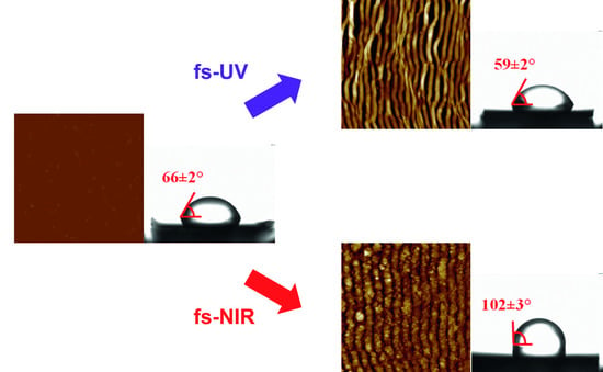
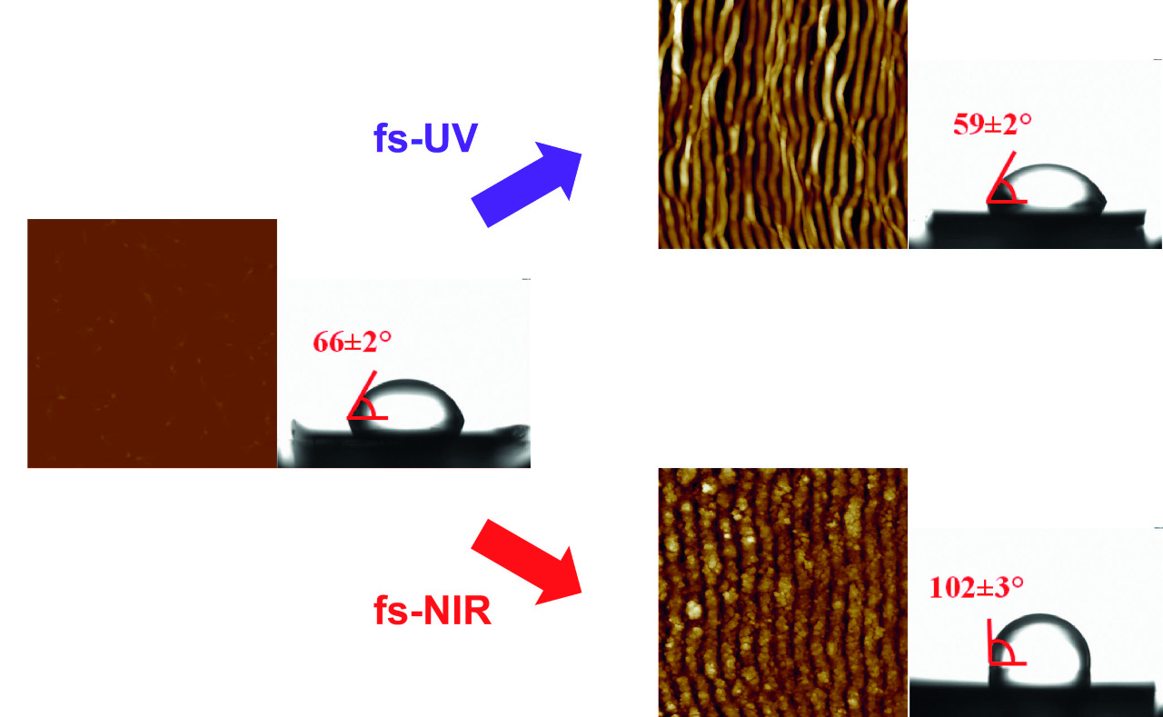
| PET/EG 0.4 wt.% | NI | 66 ± 2 | 62 ± 3 | 20 ± 2 |
| fs-UV | 59 ± 2 | 62 ± 4 | 19 ± 1 | |
| fs-NIR | 102 ± 3 | 66 ± 3 | 20 ± 2 |
| Surface Energy Components (mJ/m2) | ||||
|---|---|---|---|---|
| Material | Surface Condition | |||
| PET | NI | 26.8 | 12.1 | 38.9 |
| fs-UV | 24.2 | 15.8 | 40.0 | |
| fs-NIR | 34.9 | 0.2 | 35.1 | |
| PET/EG 0.4 wt.% | NI | 25.4 | 13.7 | 39.1 |
| fs-UV | 24.3 | 17.5 | 41.8 | |
| fs-NIR | 32.5 | 0.7 | 33.2 | |
| Material | Surface Condition | Elastic Modulus (GPA) | Adhesion Force (nN) | Deformation (nm) |
|---|---|---|---|---|
| PET | NI | 1.5 ± 0.1 | 7.9 ± 0.5 | 2.4 ± 0.2 |
| fs-UV | 2.4 ± 0.1 | 4.8 ± 0.6 | 6.1 ± 0.3 | |
| fs-NIR | 2.8 ± 0.3 | 7.1 ± 1.2 | 3.6 ± 0.6 | |
| PET/EG 0.4 wt.% | NI | 5.1 ± 0.2 | 7.4 ± 0.5 | 2.0 ± 0.1 |
| fs-UV | 5.6 ± 0.1 | 8.6 ± 0.6 | 2.1 ± 0.2 | |
| fs-NIR | 4.2 ± 0.6 | 7.7 ± 0.8 | 2.1 ± 0.3 |
Publisher’s Note: MDPI stays neutral with regard to jurisdictional claims in published maps and institutional affiliations. |
© 2022 by the authors. Licensee MDPI, Basel, Switzerland. This article is an open access article distributed under the terms and conditions of the Creative Commons Attribution (CC BY) license (https://creativecommons.org/licenses/by/4.0/).
Share and Cite
Rodríguez-Beltrán, R.I.; Prada-Rodrigo, J.; Crespo, A.; Ezquerra, T.A.; Moreno, P.; Rebollar, E. Physicochemical Modifications on Thin Films of Poly(Ethylene Terephthalate) and Its Nanocomposite with Expanded Graphite Nanostructured by Ultraviolet and Infrared Femtosecond Laser Irradiation. Polymers 2022, 14, 5243. https://doi.org/10.3390/polym14235243
Rodríguez-Beltrán RI, Prada-Rodrigo J, Crespo A, Ezquerra TA, Moreno P, Rebollar E. Physicochemical Modifications on Thin Films of Poly(Ethylene Terephthalate) and Its Nanocomposite with Expanded Graphite Nanostructured by Ultraviolet and Infrared Femtosecond Laser Irradiation. Polymers. 2022; 14(23):5243. https://doi.org/10.3390/polym14235243
Chicago/Turabian StyleRodríguez-Beltrán, René I., Javier Prada-Rodrigo, Ana Crespo, Tiberio A. Ezquerra, Pablo Moreno, and Esther Rebollar. 2022. "Physicochemical Modifications on Thin Films of Poly(Ethylene Terephthalate) and Its Nanocomposite with Expanded Graphite Nanostructured by Ultraviolet and Infrared Femtosecond Laser Irradiation" Polymers 14, no. 23: 5243. https://doi.org/10.3390/polym14235243
APA StyleRodríguez-Beltrán, R. I., Prada-Rodrigo, J., Crespo, A., Ezquerra, T. A., Moreno, P., & Rebollar, E. (2022). Physicochemical Modifications on Thin Films of Poly(Ethylene Terephthalate) and Its Nanocomposite with Expanded Graphite Nanostructured by Ultraviolet and Infrared Femtosecond Laser Irradiation. Polymers, 14(23), 5243. https://doi.org/10.3390/polym14235243