

Interfacial Properties and Melt Processability of Cellulose Acetate Propionate Composites by Melt Blending of Biofillers


Abstract

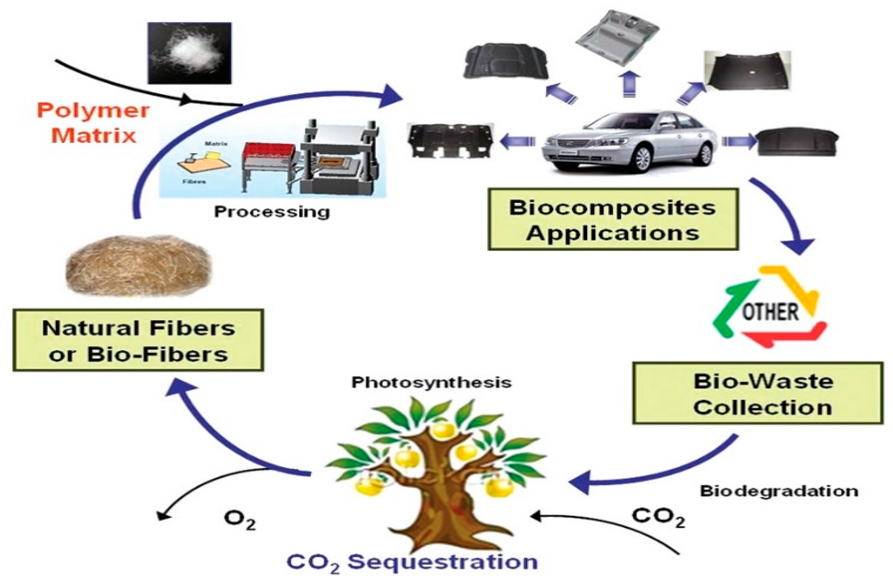
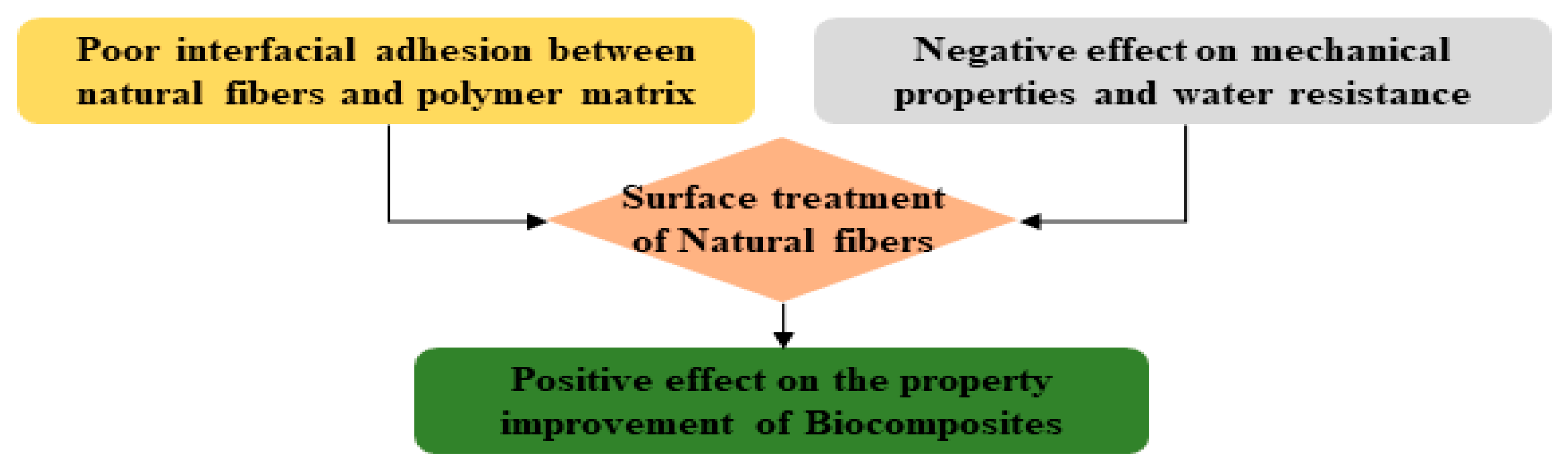
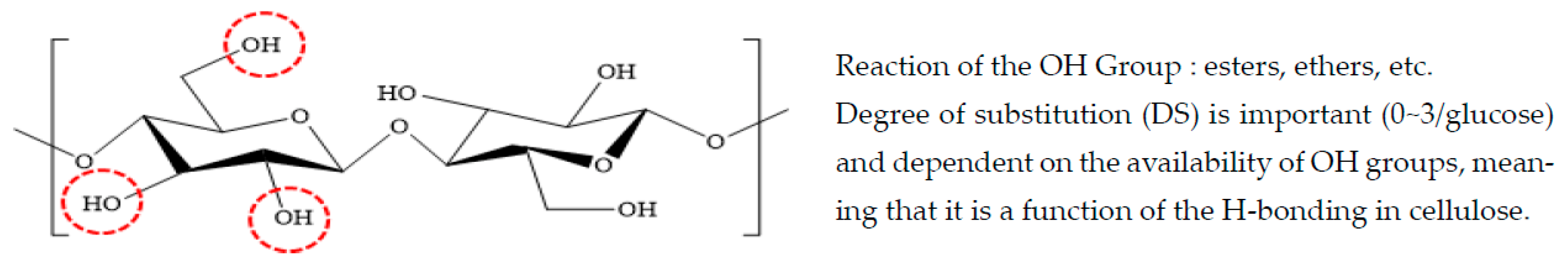
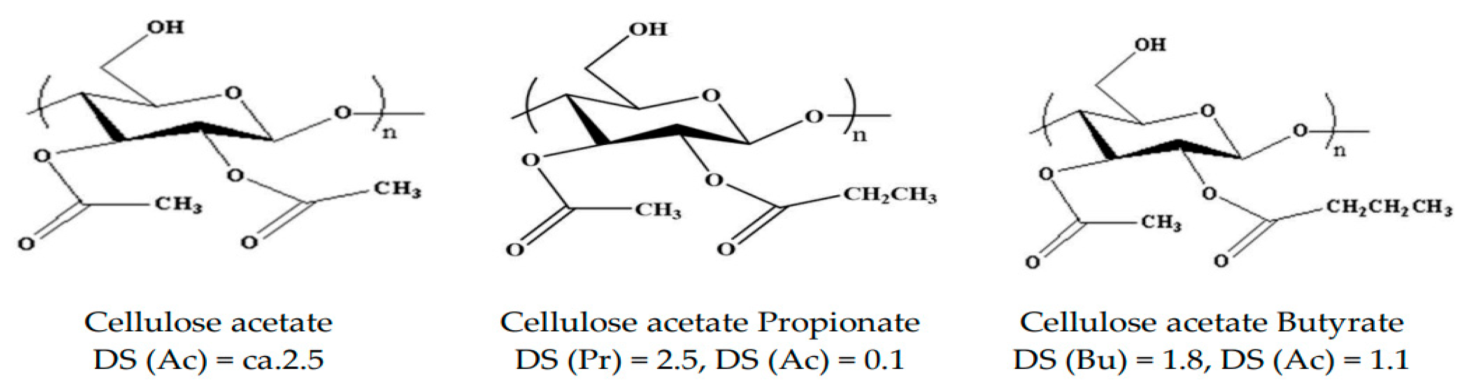
1. Introduction
2. Materials and Methods
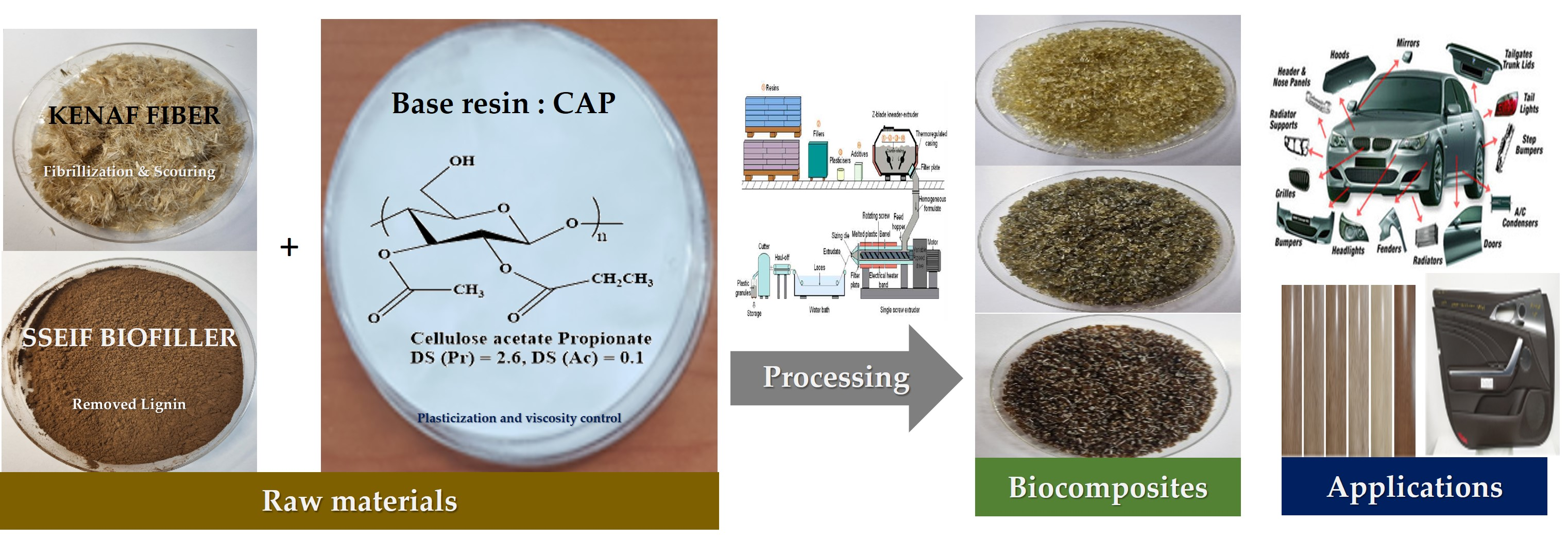
2.1. Materials
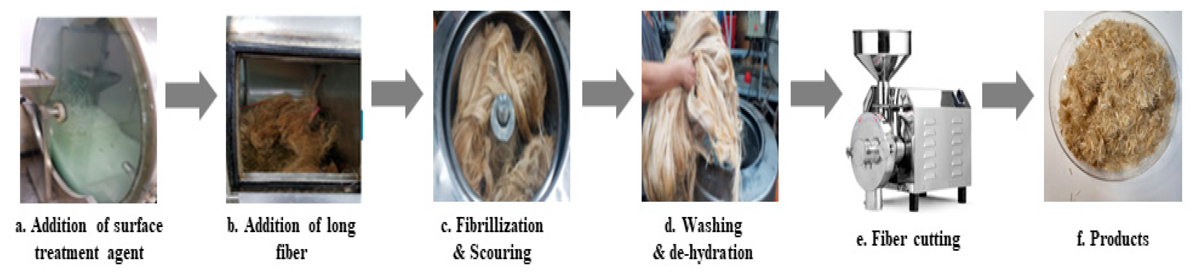
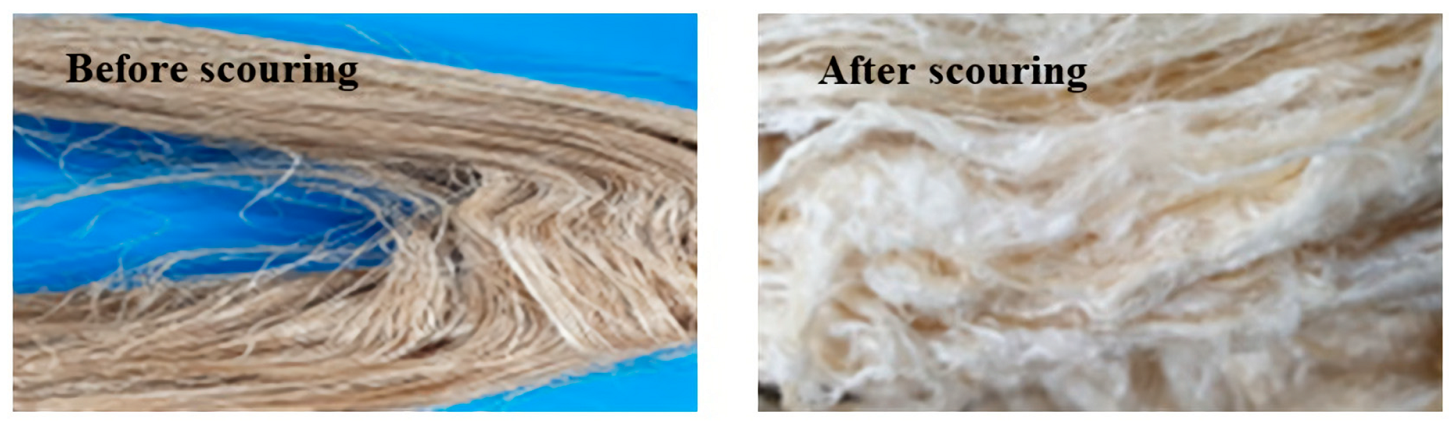
2.2. Surface Treatment of Natural Fibers
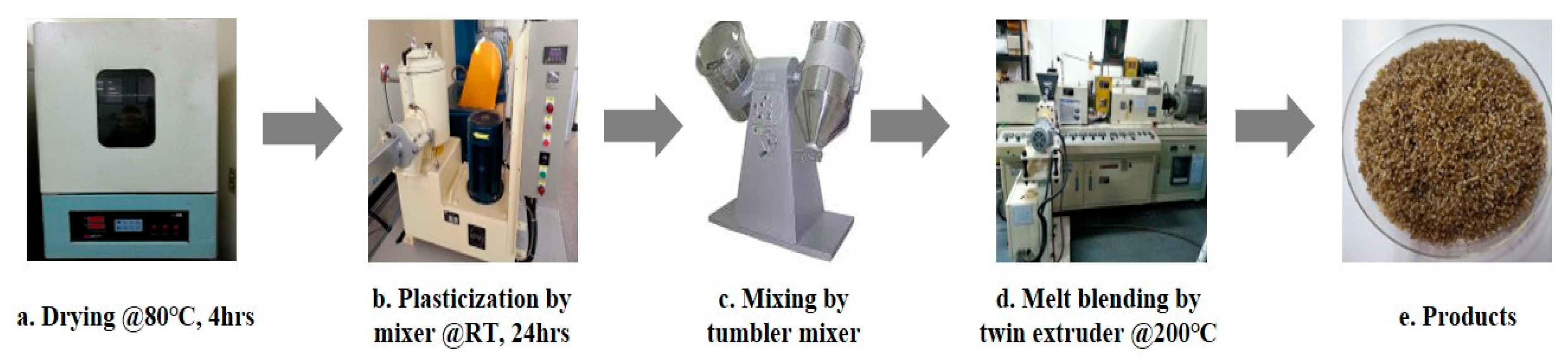
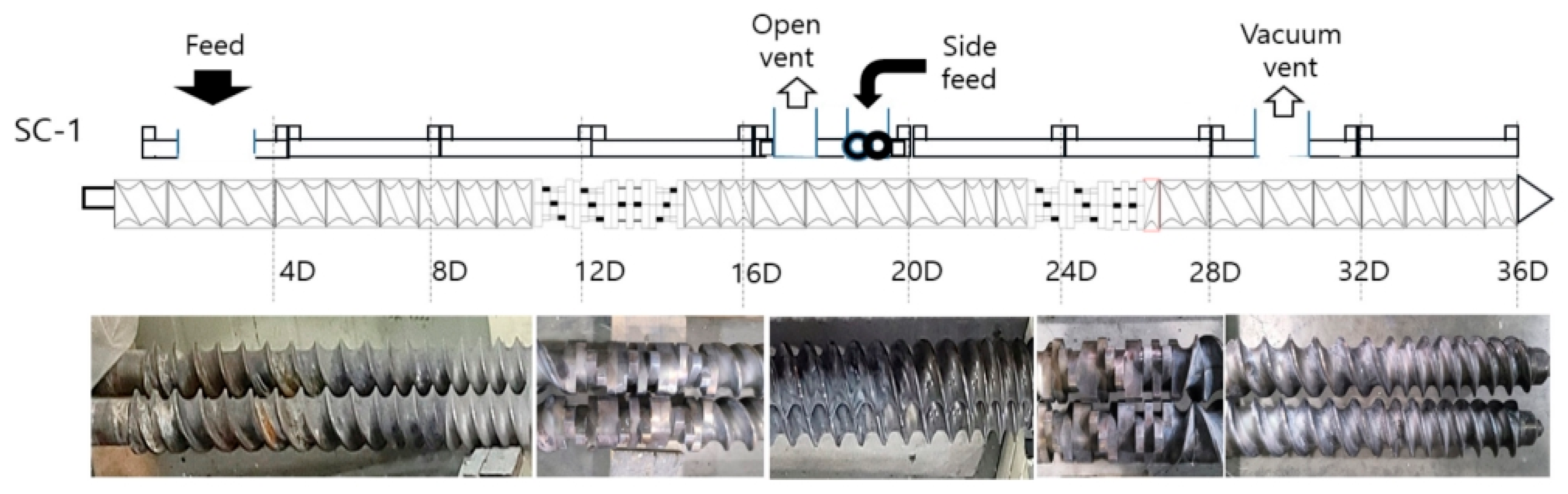
2.3. Preparation of Blending Composite and Plasticized Cellulose Acetate Propionate
2.4. Preparation of Injection Specimen
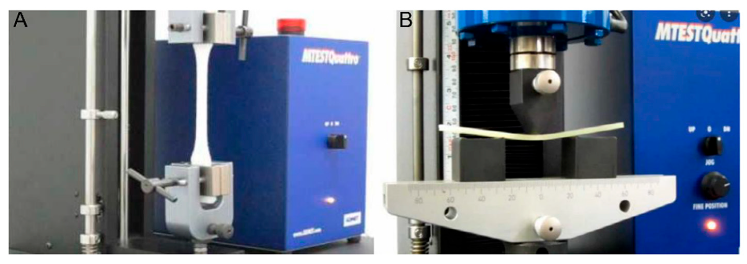
2.5. Characterization
3. Results and Discussion
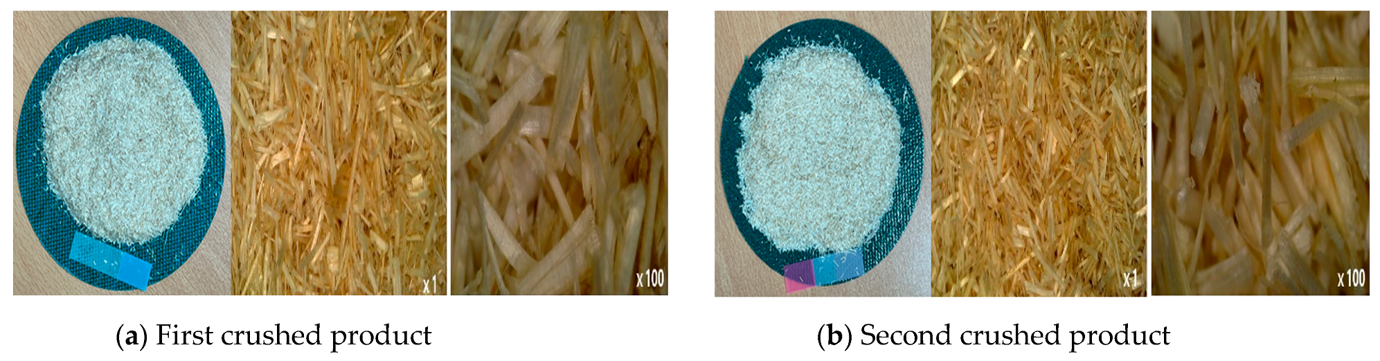
3.1. Surface Treatment of Natural Fibers
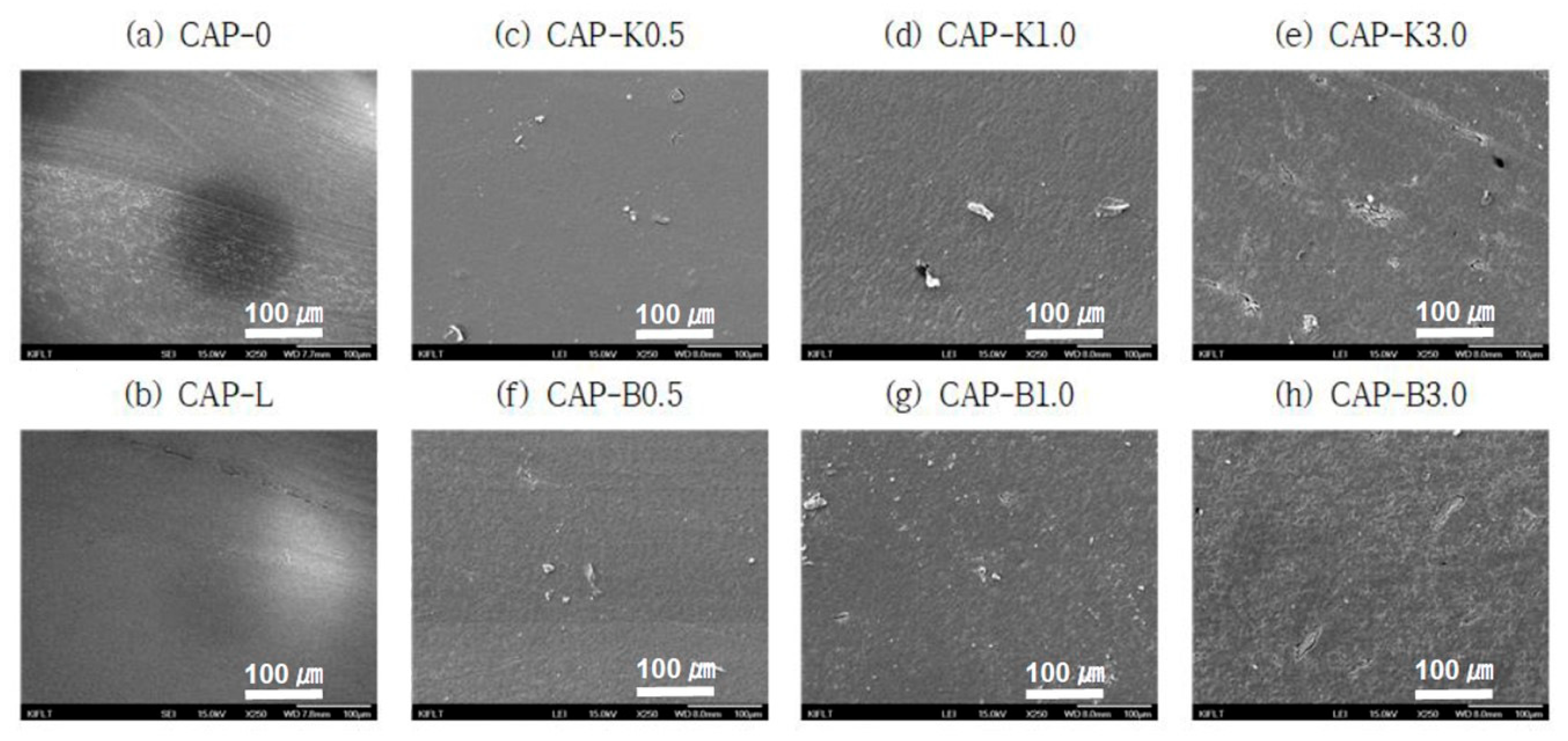
3.2. Biocomposite Structure
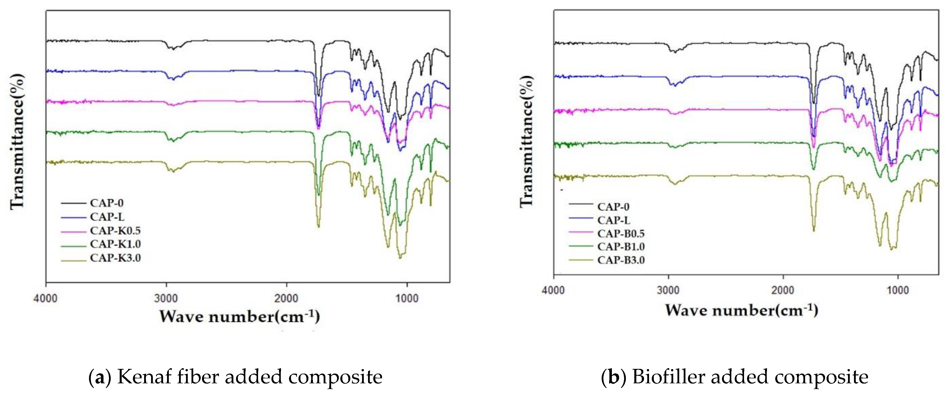
3.3. Fourier Transform Infrared Spectroscopy (FT-IR)
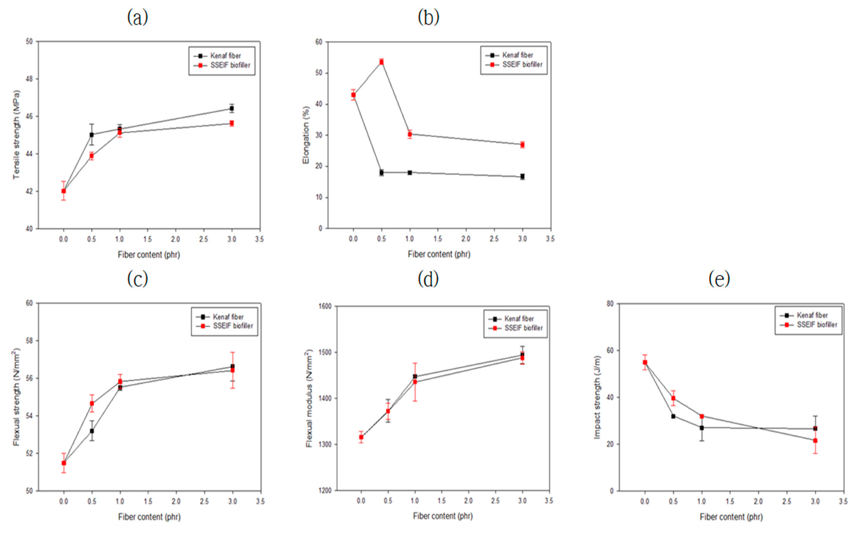
3.4. Mechanical Properties of Biocomposites
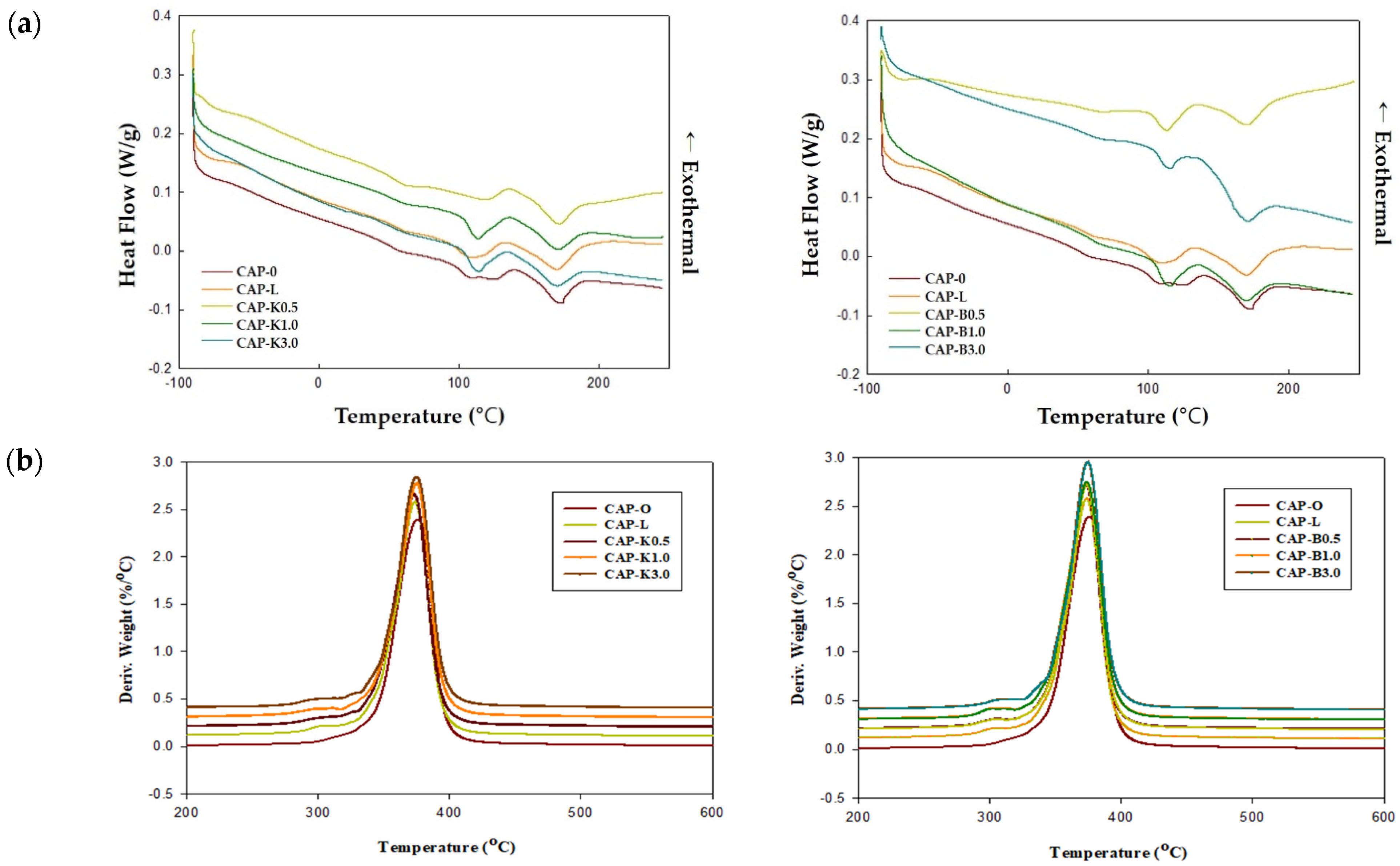
3.5. Thermal Properties of Biocomposites (DSC and TGA Analysis)
4. Conclusions
Author Contributions
Funding
Institutional Review Board Statement
Informed Consent Statement
Data Availability Statement
Conflicts of Interest
References
- Mohanty, A.; Misra, M.; Drzal, L.; Selke, S.; Harte, B.; Hinrichsen, G. Natural Fibers, Biopolymers, And Biocomposites. In Soy Protein-Based Plastics, Blends, and Composites; CRC Press: Boca Raton, FL, USA, 2005; Volume 1, pp. 1–36. ISBN 978-0849317415. [Google Scholar]
- Cho, D.; Lee, S.G.; Park, W.H.; Han, S.O. Eco-Friendly Biocomposite Materials Using Biofibers. Polym. Sci. Technol. 2002, 13, 460–476. [Google Scholar]
- Cho, D.H. Natural Fiber-Reinforced Plastics-Bio Composites. Available online: https://www.ihandler.co.kr/sub.php?contents=board&load=board_view&usemode=view&board=newtech&no=39&range=352&keyword=&keymode= (accessed on 4 January 2018).
- Cho, D.H. Low Carbon Green Resource: Natural Fiber. Fiber Technol. Ind. 2009, 13, 3–12. [Google Scholar]
- Cho, D.H. Green Composites Using Environmentally Friendly Natural Fibers. Plast. Mag. 2006, 22, 44. [Google Scholar]
- Pang, Y.S.; Yoon, S.B.; Seo, J.M.; Han, S.O.; Cho, D.H. Effect of Electron Beam Irradiation on the Interfacial and Thermal Properties of Henequen, Phenolic Biocomposites TT-Effect of Electron Beam Irradiation on the Interfacial and Thermal Properties of Henequen, Phenolic Biocomposites. J. Adhes. Interface 2005, 6, 12–17. [Google Scholar]
- Kim, H.-S.; Choi, S.-W.; Lee, B.-H.; Kim, S.; Kim, H.-J.; Cho, C.W.; Cho, D. Thermal Properties of Bio Flour-Filled Polypropylene Bio-Composites with Different Pozzolan Contents. J. Therm. Anal. Calorim. 2007, 89, 821–827. [Google Scholar] [CrossRef]
- Liu, J.L.; Xia, R. A unified analysis of a micro-beam, droplet and CNT ring adhered on a substrate: Calculation of variation with movable boundaries. Acta Mech. Sin. 2013, 29, 62–72. [Google Scholar] [CrossRef]
- Lee, S.M.; Cho, D.; Park, W.H.; Lee, S.G.; Han, S.O.; Drzal, L.T. Novel Silk/Poly(Butylene Succinate) Biocomposites: The Effect of Short Fibre Content on Their Mechanical and Thermal Properties. Compos. Sci. Technol. 2005, 65, 647–657. [Google Scholar] [CrossRef]
- Han, S.O.; Cho, D.; Park, W.H.; Drzal, L.T. Henequen/Poly(Butylene Succinate) Biocomposites: Electron Beam Irradiation Effects on Henequen Fiber and the Interfacial Properties of Biocomposites. Compos. Interfaces 2006, 13, 231–247. [Google Scholar] [CrossRef]
- Donghwan, C.; Seo, J.; Park, W.H.; Han, S.; Hwang, T.; Choi, C.; Jung, S. Improvement of the Interfacial, Flexural, and Thermal Properties of Jute/Poly(Lactic Acid) Biocomposites by Fiber Surface Treatments. J. Biobased Mater. Bioenergy 2007, 1, 331–340. [Google Scholar] [CrossRef]
- Cho, D.; Lee, H.S.; Han, S.O.; Drzal, L.T. Effects of E-Beam Treatment on the Interfacial and Mechanical Properties of Henequen/Polypropylene Composites. Adv. Compos. Mater. 2007, 16, 315–334. [Google Scholar] [CrossRef]
- Lee, H.S.; Cho, D.; Han, S.O. Effect of Natural Fiber Surface Treatments on the Interfacial and Mechanical Properties of Henequen/Polypropylene Biocomposites. Macromol. Res. 2008, 16, 411–417. [Google Scholar] [CrossRef]
- Cho, D.; Kim, H.-J.; Drzal, L.T. Surface Treatment and Characterization of Natural Fibers: Effects on the Properties of Biocomposites. Polym. Compos. 2013, 133–177. [Google Scholar]
- Han, S.O.; Ahn, H.J.; Cho, D. Hygrothermal Effect on Henequen or Silk Fiber Reinforced Poly(Butylene Succinate) Biocomposites. Compos. Part B Eng. 2010, 41, 491–497. [Google Scholar] [CrossRef]
- Woo, Y.; Cho, D. Effect of Aluminum Trihydroxide on Flame Retardancy and Dynamic Mechanical and Tensile Properties of Kenaf/Poly(Lactic Acid) Green Composites. Adv. Compos. Mater. 2013, 22, 451–464. [Google Scholar] [CrossRef]
- Woo, Y.; Donghwan, C. Effects of Kenaf Fibers Coated with Aluminum Trihydroxide on Limiting Oxygen Index and Thermal and Mechanical Properties of Biocomposites. Polym. Korea 2016, 40, 568. [Google Scholar] [CrossRef]
- Yu, H.; Gong, L.; Qu, Z.; Hao, P.; Liu, J.; Fu, L. Wettability enhancement of hydrophobic artificial sandstones by using the pulsed microwave plasma jet. Colloid Interface Sci. Commun. 2020, 36, 100266. [Google Scholar] [CrossRef]
- Khazraji, A.C.; Robert, S. Self-Assembly and Intermolecular Forces When Cellulose and Water Interact Using Molecular Modeling. J. Nanomater. 2013, 2013, 12. [Google Scholar] [CrossRef]
- Lee, S.H.; Lee, S.Y.; Nam, J.D.; Lee, Y.K. Preparation and properties of plasticized cellulose diacetate using triacetine/epoxidized soybean oil. Polymer 2006, 30, 70–74. [Google Scholar]
- Edgar, K.J.; Buchanan, C.M.; Debenham, J.S.; Rundquist, P.A.; Seiler, B.D.; Shelton, M.C.; Tindall, D. Advances in Cellulose Ester Performance and Application. Prog. Polym. Sci. 2001, 26, 1605–1688. [Google Scholar] [CrossRef]
- Lee, S. Method for Manufacturing Bio-Fillers for Plastics and Bio-Fillers by Using the Same. Korea Patent KR101962239B1, 2019. [Google Scholar]
- Lee, J.; Lee, J.; Jeon, H.; Park, H.; Oh, S.; Chung, I. Studies on the Melt Viscosity and Physico-Chemical Properties of Cellulose Acetate Propionate Composites with Lactic Acid Blends. Mol. Cryst. Liq. Cryst. 2020, 707, 8–20. [Google Scholar] [CrossRef]
- Pappas, C.S.; Tarantilis, P.A.; Polissiou, M.G. Isolation and Spectroscopic Study of Pectic Substances from Kenaf (HibiscusCannabinus L.). Nat. Prod. Res. 2010, 17, 171–176. [Google Scholar] [CrossRef] [PubMed]
- Aritkhodzhaev, K.A.; Arifkhodzhaev, A.O.; Yusupov, A.M. Pectin from Green Kenaf Bast. Chem. Nat. Compd. 1995, 31, 159–162. [Google Scholar] [CrossRef]
- Falana, O.; Aluko, O.; Adetan, D.; Osunbitan, J. The physical properties and strength characteristicsof kenaf plants. Res. Agric. Eng. 2019, 65, 131–136. [Google Scholar] [CrossRef]
- Wang, C.; Bai, S.; Yue, X.; Long, B.; Choo-Smith, L. Relationship between Chemical Composition, Crystallinity, Orientation and Tensile Strength of Kenaf Fiber. Fibers Polym. 2016, 17, 1757–1764. [Google Scholar] [CrossRef]
- Hossain, M.M.; Subbiah, V.K.; Siddiquee, S. Augmented Retting Effect on Kenaf Fibers Using Alkalophilic Pectinase-Producing Bacteria in Combination with Water Solvents. Appl. Sci. 2022, 12, 7136. [Google Scholar] [CrossRef]
- Edeerozey, A.M.; Akil, H.M.; Azhar, A.B.; Ariffin, M.Z. Chemical modification of Kenaf fibers. Mater. Lett. 2007, 61, 2023–2025. [Google Scholar] [CrossRef]
- Kim, S.J.; Moon, J.B.; Kim, G.H.; Ha, C.S. Mechanical properties of polypropylene/natural fiber composites: Comparison of wood fiber and cotton fiber. Polym. Test. 2008, 27, 801–806. [Google Scholar] [CrossRef]
- Lee, S.; Kim, H. A Review on the Screw Configuration of Intermeshing Co-Rotating Twin Screw Extruder. Korean Chem. Eng. Res. 2021, 59, 305–315. [Google Scholar] [CrossRef]
- Yamaguchi, M.; Lee, S.; Manaf, M.E.A.; Tsuji, M.; Yokohara, T. Modification of Orientation Birefringence of Cellulose Ester by Addition of Poly(Lactic Acid). Eur. Polym. J. 2010, 46, 2269–2274. [Google Scholar] [CrossRef]


| Refining Agent | Weight Loss According to Refining (or Scouring) Time | |||||
|---|---|---|---|---|---|---|
| 2 h @60 °C | 4 h @60 °C | 6 h @60 °C | ||||
| 3%-NaOH aqueous solution |  |  |  |  |  |  |
| 40.94% | 45.22% | 46.13% | ||||
| 3%-NaOH aqueous solution + α-amylase 2wt% |  |  |  |  |  |  |
| 41.38% | 44.9% | 48.78% | ||||
| 3%-NaOH aqueous solution + α-amylase 4wt% |  |  |  |  |  |  |
| 44.79% | 43.18% | 43.72% | ||||
| 6%-NaOH aqueous solution |  |  |  |  |  |  |
| 44.6% | 47.12% | 47.73% | ||||
| 6%-NaOH aqueous solution + α-amylase 2wt% |  |  |  |  |  |  |
| 41.44% | 44.81% | 43.86% | ||||
| 6%-NaOH aqueous solution + α-amylase 4wt% |  |  |  |  |  |  |
| 41.47% | 43.27% | 44.57% | ||||
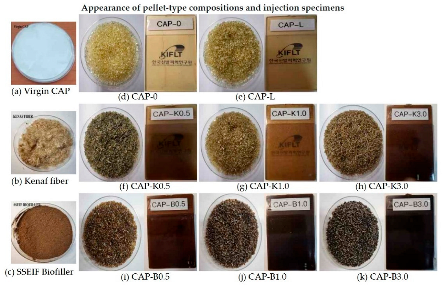
| Sample Code | Materials | |||||
|---|---|---|---|---|---|---|
| CAP482-20 | PEG300 | Adipic Acid Polyester | Lactic Acid | Kenaf Fiber | SSEIF Biofiller | |
| CAP-0 | 100 | 5 | 5 | - | - | |
| CAP-L | 100 | 5 | 5 | 2.5 | - | - |
| CAP-K0.5 | 100 | 5 | 5 | 2.5 | 0.5 | - |
| CAP-K1.0 | 100 | 5 | 5 | 2.5 | 1.0 | - |
| CAP-K3.0 | 100 | 5 | 5 | 2.5 | 3.0 | - |
| CAP-B0.5 | 100 | 5 | 5 | 2.5 | - | 0.5 |
| CAP-B1.0 | 100 | 5 | 5 | 2.5 | - | 1.0 |
| CAP-B3.0 | 100 | 5 | 5 | 2.5 | - | 3.0 |
| No. | CAP/PEG300/Adipic Acid Polyester/Lactic Acid/Biofiller (phr) | Hardness (D type) | Density (g/cc) | Tensile Strength (MPa) | Elongation (%) | Flexural Strength (MPa) | Flexural Modulus (MPa) | Impact Strength (J/m) |
|---|---|---|---|---|---|---|---|---|
| CAP-0 | 100/5/5/0/0 | 72 | 1.229 | 47.7 | 45 | 59.5 | 1510 | 43 |
| CAP-L | 100/5/5/2.5/0 | 70 | 1.231 | 42.9 | 43 | 51.5 | 1316 | 55 |
| CAP-K0.5 | 100/5/5/2.5/K0.5 | 70 | 1.231 | 45.0 | 18 | 53.2 | 1373 | 32 |
| CAP-K1.0 | 100/5/5/2.5/K1.0 | 69 | 1.230 | 45.3 | 18 | 55.5 | 1448 | 27 |
| CAP-K3.0 | 100/5/5/2.5/K3.0 | 68 | 1.230 | 46.4 | 17 | 56.6 | 1494 | 27 |
| CAP-B0.5 | 100/5/5/2.5/B0.5 | 71 | 1.228 | 43.7 | 54 | 54.7 | 1372 | 32 |
| CAP-B1.0 | 100/5/5/2.5/B1.0 | 72 | 1.228 | 45.1 | 30 | 56.4 | 1436 | 32 |
| CAP-B3.0 | 100/5/5/2.5/B3.0 | 75 | 1.232 | 45.6 | 27 | 55.8 | 1488 | 22 |
| No. | CAP/PEG300/Adipic Acid Polyester/Lactic Acid/BIOFILLER (phr) | Biofiller (phr) | Tg (°C) | Tm (°C)/ΔH(J/g) | Tm (°C)/ΔH(J/g) | Td * (°C) |
|---|---|---|---|---|---|---|
| CAP-0 | 100/5/5/0/0 | 0 | −45.01/50.04 | 107.79/4.984 | 171.73/5.945 | 375.41 |
| CAP-L | 100/5/5/2.5/0 | 0 | −43.64/55.69 | 108.35/5.510 | 170.01/7.164 | 374.40 |
| CAP-K0.5 | 100/5/5/2.5/K0.5 | K0.5 | −38.01/53.84 | 118.14/3.409 | 169.87/6.243 | 372.38 |
| CAP-K1.0 | 100/5/5/2.5/K1.0 | K1.0 | −47.73/51.32 | 113.34/5.496 | 168.47/5.826 | 375.35 |
| CAP-K3.0 | 100/5/5/2.5/K3.0 | K3.0 | −44.28/50.56 | 113.22/4.739 | 167.09/5.761 | 374.40 |
| CAP-B0.5 | 100/5/5/2.5/B0.5 | B0.5 | −38.84/53.46 | 113.54/3.935 | 170.71/6.141 | 373.39 |
| CAP-B1.0 | 100/5/5/2.5/B1.0 | B1.0 | −43.57/57.79 | 114.41/5.200 | 167.74/5.971 | 373.39 |
| CAP-B3.0 | 100/5/5/2.5/B3.0 | B3.0 | −42.83/53.08 | 113.34/2.642 | 164.68/8.213 | 374.40 |
Publisher’s Note: MDPI stays neutral with regard to jurisdictional claims in published maps and institutional affiliations. |
© 2022 by the authors. Licensee MDPI, Basel, Switzerland. This article is an open access article distributed under the terms and conditions of the Creative Commons Attribution (CC BY) license (https://creativecommons.org/licenses/by/4.0/).
Share and Cite
Lee, J.-E.; Shim, S.-B.; Park, J.-H.; Chung, I. Interfacial Properties and Melt Processability of Cellulose Acetate Propionate Composites by Melt Blending of Biofillers. Polymers 2022, 14, 4286. https://doi.org/10.3390/polym14204286
Lee J-E, Shim S-B, Park J-H, Chung I. Interfacial Properties and Melt Processability of Cellulose Acetate Propionate Composites by Melt Blending of Biofillers. Polymers. 2022; 14(20):4286. https://doi.org/10.3390/polym14204286
Chicago/Turabian StyleLee, Ji-Eun, Seung-Bo Shim, Jae-Hyung Park, and Ildoo Chung. 2022. "Interfacial Properties and Melt Processability of Cellulose Acetate Propionate Composites by Melt Blending of Biofillers" Polymers 14, no. 20: 4286. https://doi.org/10.3390/polym14204286
APA StyleLee, J.-E., Shim, S.-B., Park, J.-H., & Chung, I. (2022). Interfacial Properties and Melt Processability of Cellulose Acetate Propionate Composites by Melt Blending of Biofillers. Polymers, 14(20), 4286. https://doi.org/10.3390/polym14204286