

Anatomically and Biomechanically Relevant Monolithic Total Disc Replacement Made of 3D-Printed Thermoplastic Polyurethane

 , , , and
Abstract
1. Introduction
2. Materials and Methods
2.1. Materials
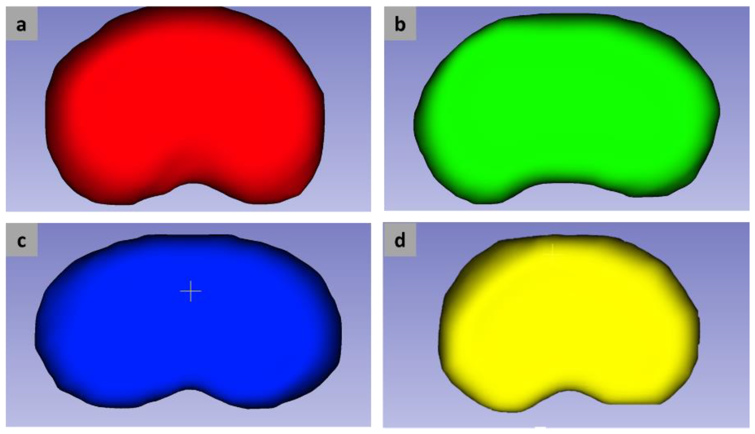
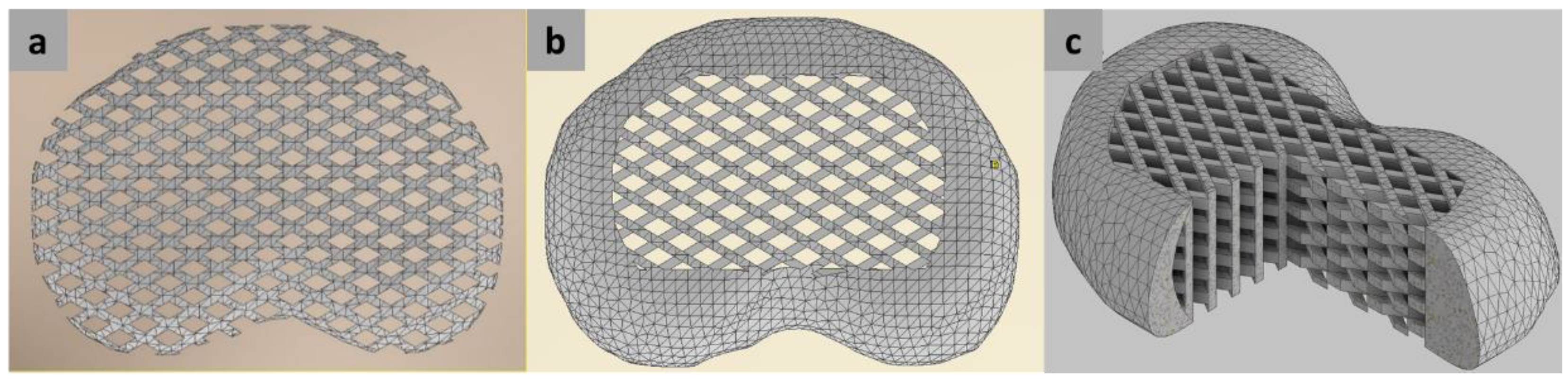
2.2. Design and Preparation
2.3. Lattice Configuration
2.4. Fabrication
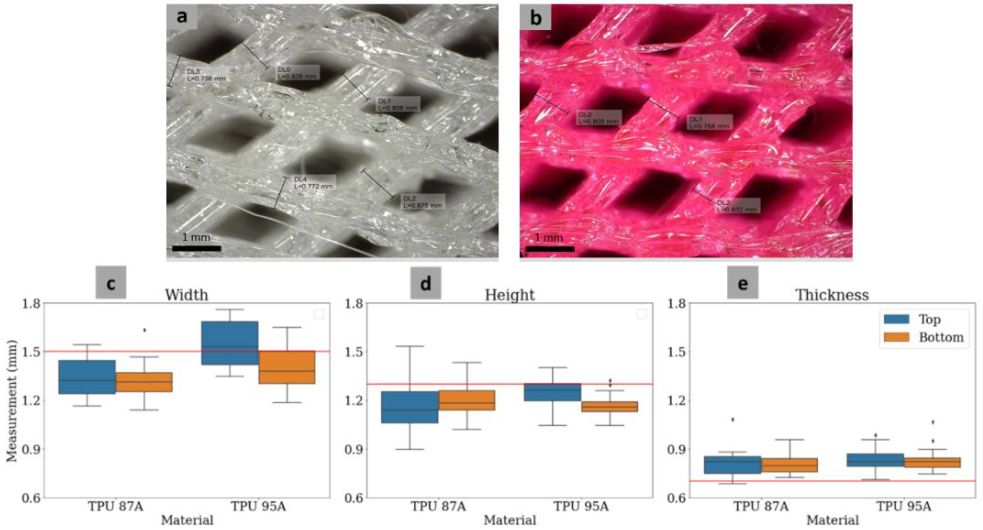
2.5. Geometrical Evaluation
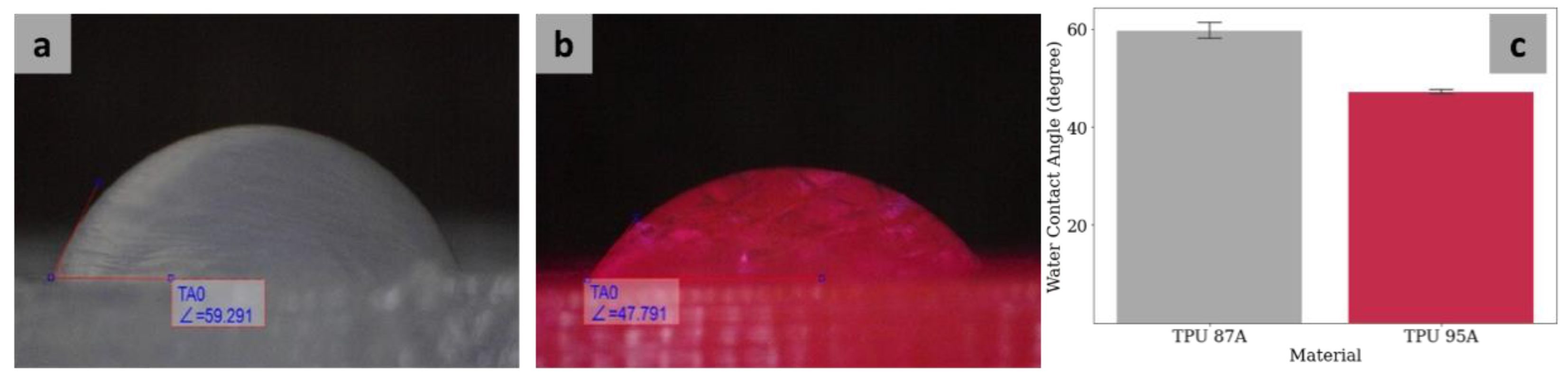
2.6. Wettability
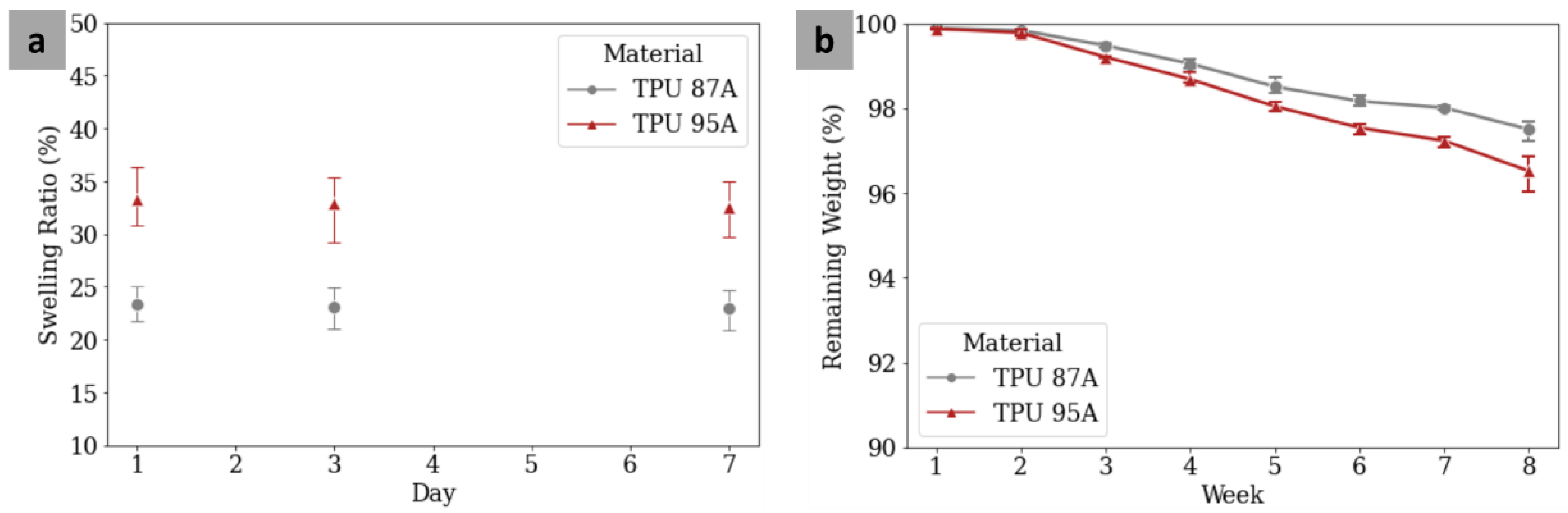
2.7. Swelling Test
- ms→is the MTDR mass after swelling after a certain period, and
- md→is the initial MTDR mass.
2.8. Degradation Test
- m0→is the MTDR initial mass, and
- m1→is the MTDR mass after vacuum drying for each week interval.
2.9. Compressive Test
2.10. Analytical Approach
- El→is the elastic modulus of the lattice model,
- Er→is the elastic modulus of the rigid model,
- Vnp→is the volume of the nucleus pulposus, and
- Vaf→is the volume of the annulus fibrosus.
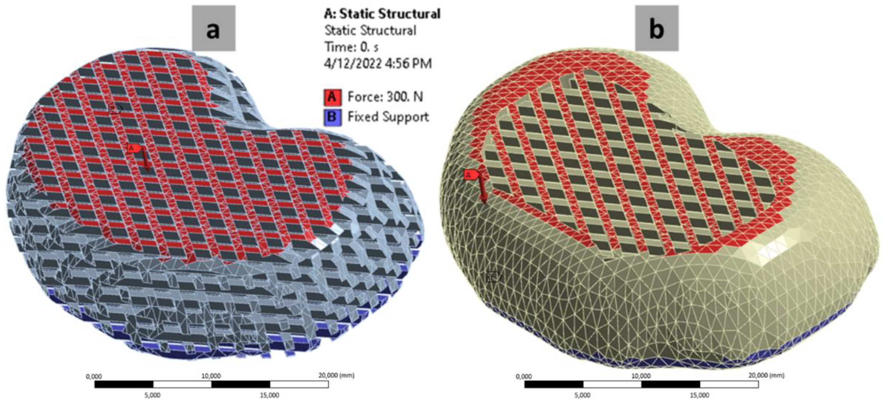
2.11. Finite Element Analysis (FEA)
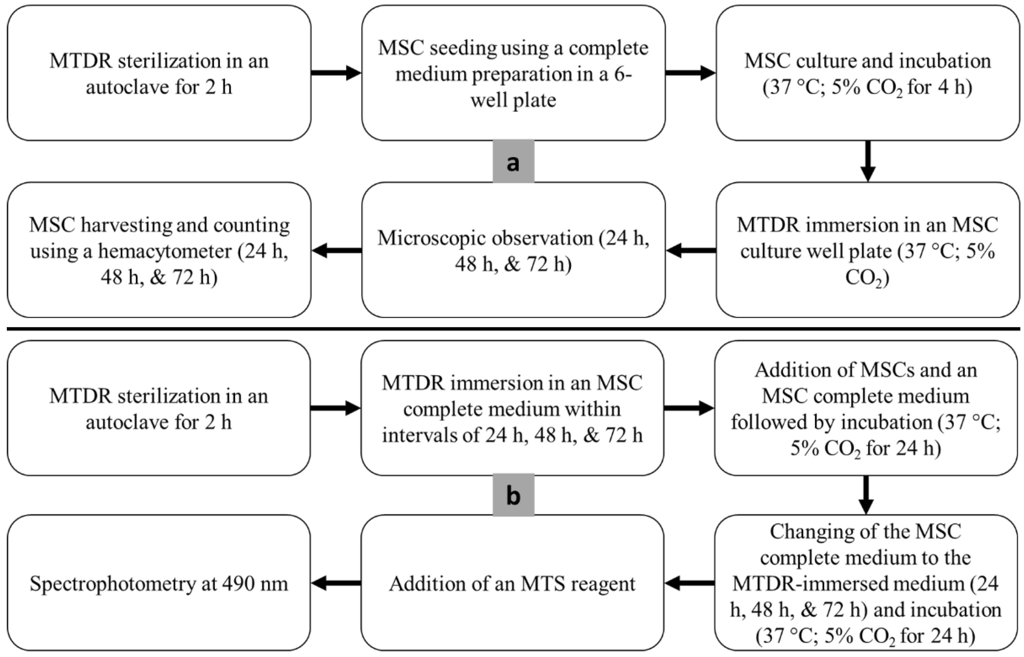
2.12. Cytotoxicity Assay
2.13. Statistical Analysis
3. Results
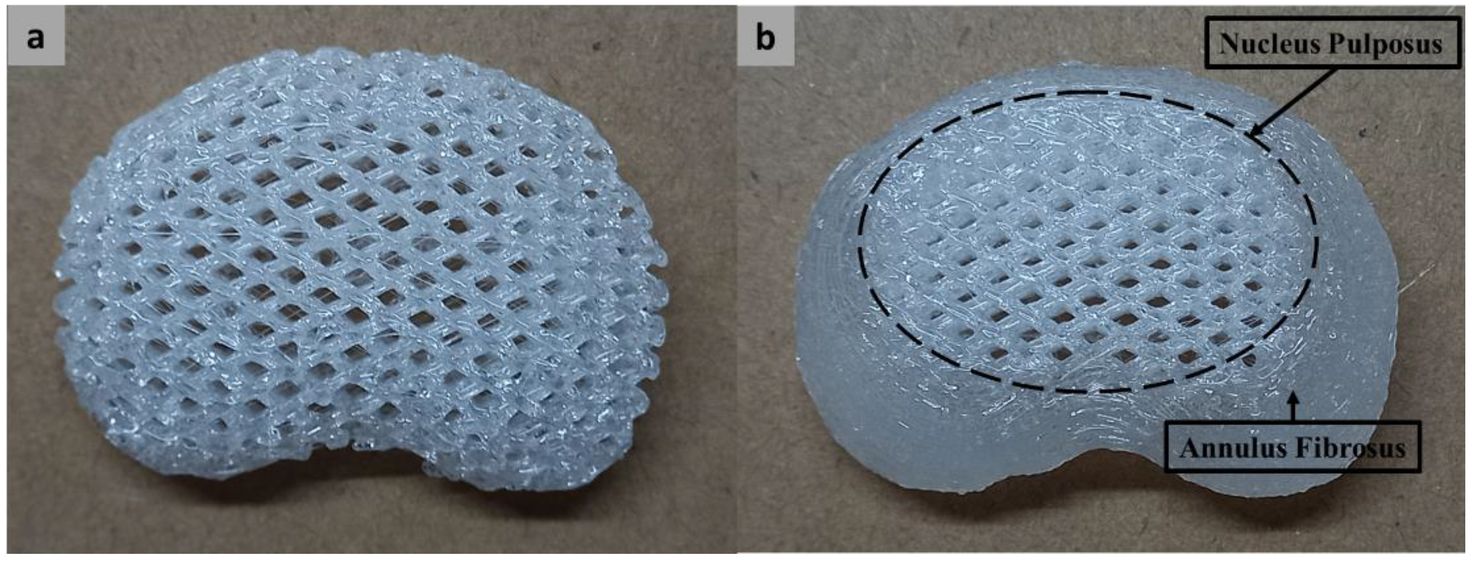
3.1. Fabrication
3.2. Geometrical Evaluation
3.3. Wettability
3.4. Swelling Ratio
3.5. Degradation Rate
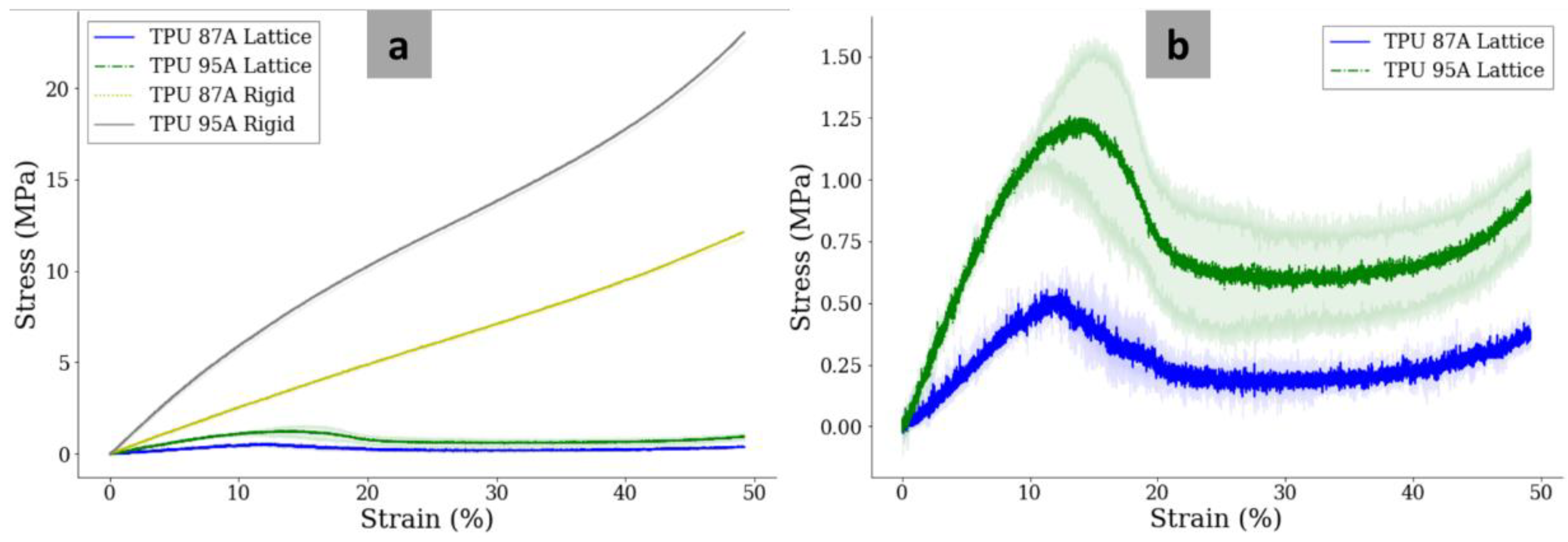
3.6. Mechanical Properties
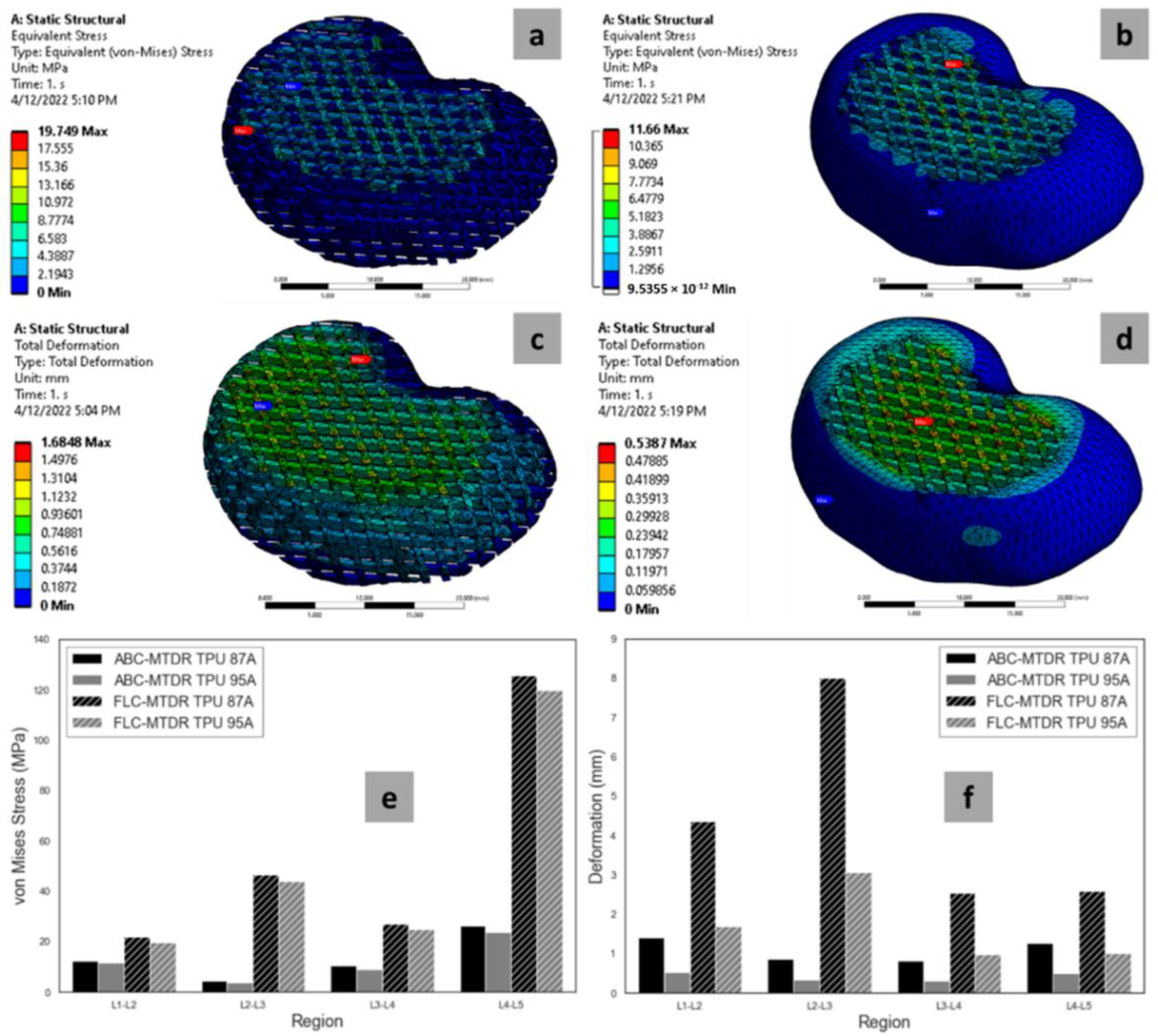
3.7. FEA Results
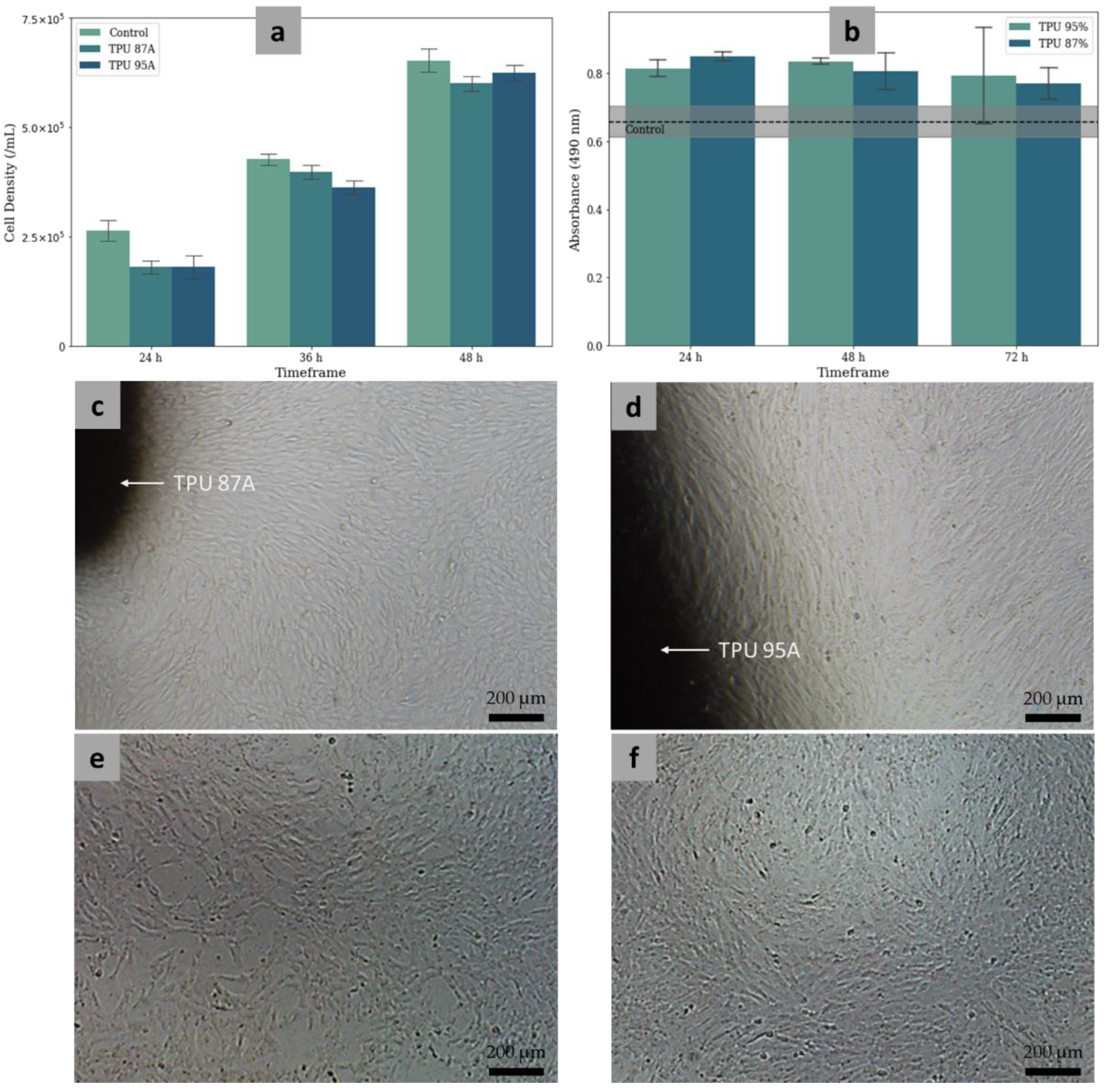
3.8. Cytotoxicity
4. Discussion
5. Conclusions
- The ABC-MTDRs made of TPU 87A and TPU 95A were successfully fabricated using an FFF-based 3D printing approach following the anatomical features of IVDs with tolerable fabrication error rates;
- The lattice and rigid structures mimicked the mechanical properties of the NP and AF, respectively, as indicated by the similar elastic moduli between the fabricated structures and the respective tissues. When the NP and AF features were combined as an ABC-MTDR entity, the elastic modulus of the ABC-MTDR was also similar to an entire IVD;
- The WCA measurement and swelling test results confirmed the hydrophilicity and water retention ability of the two materials, like the NP;
- The degradation rates of the two materials were projected to be no less than 4 years, which are arguably acceptable considering the prospects of an implant to support the IVD regeneration, instead of becoming a prosthesis only;
- The direct and indirect cytotoxicity assay results indicated that the MTDR was non-cytotoxic, allowing for cells to grow on the surfaces of the materials.
6. Future Perspective
Author Contributions
Funding
Institutional Review Board Statement
Data Availability Statement
Acknowledgments
Conflicts of Interest
References
- Buchbinder, R.; Blyth, F.M.; March, L.M.; Brooks, P.; Woolf, A.D.; Hoy, D.G. Placing the Global Burden of Low Back Pain in Context. Best Pract. Res. Clin. Rheumatol. 2013, 27, 575–589. [Google Scholar] [CrossRef] [PubMed]
- Geurts, J.W.; Willems, P.C.; Kallewaard, J.-W.; van Kleef, M.; Dirksen, C. The Impact of Chronic Discogenic Low Back Pain: Costs and Patients’ Burden. Pain Res. Manag. 2018, 2018, 4696180. [Google Scholar] [CrossRef] [PubMed]
- Wu, A.; March, L.; Zheng, X.; Huang, J.; Wang, X.; Zhao, J.; Blyth, F.M.; Smith, E.; Buchbinder, R.; Hoy, D. Global Low Back Pain Prevalence and Years Lived with Disability from 1990 to 2017: Estimates from the Global Burden of Disease Study 2017. Ann. Transl. Med. 2020, 8, 299. [Google Scholar] [CrossRef] [PubMed]
- Wang, L.; Ye, H.; Li, Z.; Lu, C.; Ye, J.; Liao, M.; Chen, X. Epidemiological Trends of Low Back Pain at the Global, Regional, and National Levels. Eur. Spine J. 2022, 31, 953–962. [Google Scholar] [CrossRef] [PubMed]
- Malandrino, A.; Noailly, J.; Lacroix, D. The Effect of Sustained Compression on Oxygen Metabolic Transport in the Intervertebral Disc Decreases with Degenerative Changes. PLoS Comput. Biol. 2011, 7, e1002112. [Google Scholar] [CrossRef]
- Whatley, B.R.; Wen, X. Intervertebral Disc (IVD): Structure, Degeneration, Repair and Regeneration. Mater. Sci. Eng. C 2012, 32, 61–77. [Google Scholar] [CrossRef]
- Oichi, T.; Taniguchi, Y.; Oshima, Y.; Tanaka, S.; Saito, T. Pathomechanism of Intervertebral Disc Degeneration. JOR Spine 2020, 3, e1076. [Google Scholar] [CrossRef]
- Othman, Y.A.; Verma, R.; Qureshi, S.A. Artificial Disc Replacement in Spine Surgery. Ann. Transl. Med. 2019, 7, S170. [Google Scholar] [CrossRef]
- Vital, J.-M.; Boissière, L. Total Disc Replacement. Orthop. Traumatol. Surg. Res. 2014, 100, S1–S14. [Google Scholar] [CrossRef]
- Zigler, J.; Gornet, M.F.; Ferko, N.; Cameron, C.; Schranck, F.W.; Patel, L. Comparison of Lumbar Total Disc Replacement with Surgical Spinal Fusion for the Treatment of Single-Level Degenerative Disc Disease: A Meta-Analysis of 5-Year Outcomes From Randomized Controlled Trials. Glob. Spine J. 2018, 8, 413–423. [Google Scholar] [CrossRef]
- Nie, H.; Chen, G.; Wang, X.; Zeng, J. Comparison of Total Disc Replacement with Lumbar Fusion: A Meta-Analysis of Randomized Controlled Trials. J. Coll. Physicians Surg. Pak. 2015, 25, 60–67. [Google Scholar]
- Ding, F.; Jia, Z.; Zhao, Z.; Xie, L.; Gao, X.; Ma, D.; Liu, M. Total Disc Replacement versus Fusion for Lumbar Degenerative Disc Disease: A Systematic Review of Overlapping Meta-Analyses. Eur. Spine J. 2017, 26, 806–815. [Google Scholar] [CrossRef] [PubMed]
- Jacobs, W.C.H.; van der Gaag, N.A.; Kruyt, M.C.; Tuschel, A.; de Kleuver, M.; Peul, W.C.; Verbout, A.J.; Oner, F.C. Total Disc Replacement for Chronic Discogenic Low Back Pain: A Cochrane Review. Spine 2013, 38, 24–36. [Google Scholar] [CrossRef] [PubMed]
- Jacobs, W.; Van der Gaag, N.A.; Tuschel, A.; de Kleuver, M.; Peul, W.; Verbout, A.; Oner, F.C. Total Disc Replacement for Chronic Back Pain in the Presence of Disc Degeneration. Cochrane Database Syst. Rev. 2012, 9, 1–59. [Google Scholar] [CrossRef] [PubMed]
- Van den Eerenbeemt, K.D.; Ostelo, R.W.; van Royen, B.J.; Peul, W.C.; van Tulder, M.W. Total Disc Replacement Surgery for Symptomatic Degenerative Lumbar Disc Disease: A Systematic Review of the Literature. Eur. Spine J. 2010, 19, 1262–1280. [Google Scholar] [CrossRef]
- Shankar, H.; Scarlett, J.A.; Abram, S.E. Anatomy and Pathophysiology of Intervertebral Disc Disease. Tech. Reg. Anesth. Pain Manag. 2009, 13, 67–75. [Google Scholar] [CrossRef]
- Christiani, T.R.; Baroncini, E.; Stanzione, J.; Vernengo, A.J. In Vitro Evaluation of 3D Printed Polycaprolactone Scaffolds with Angle-Ply Architecture for Annulus Fibrosus Tissue Engineering. Regen. Biomater. 2019, 6, 175–184. [Google Scholar] [CrossRef]
- Bhunia, B.K.; Dey, S.; Bandyopadhyay, A.; Mandal, B.B. 3D Printing of Annulus Fibrosus Anatomical Equivalents Recapitulating Angle-Ply Architecture for Intervertebral Disc Replacement. Appl. Mater. Today 2021, 23, 101031. [Google Scholar] [CrossRef]
- Kandil, K.; Kaoua, S.A.; Mesbah, A.; Voznyak, Y.; Zaïri, F.; Zaïri, F. A Novel Bio-Inspired Hydrogel-Based Lattice Structure to Mechanically Mimic Human Annulus Fibrosus: A Finite Element Study. Int. J. Mech. Sci. 2021, 211, 106775. [Google Scholar] [CrossRef]
- Priyadarshani, P.; Li, Y.; Yao, L. Advances in Biological Therapy for Nucleus Pulposus Regeneration. Osteoarthr. Cartil. 2016, 24, 206–212. [Google Scholar] [CrossRef] [PubMed]
- Mano, J.F.; Silva, G.A.; Azevedo, H.S.; Malafaya, P.B.; Sousa, R.A.; Silva, S.S.; Boesel, L.F.; Oliveira, J.M.; Santos, T.C.; Marques, A.P.; et al. Natural Origin Biodegradable Systems in Tissue Engineering and Regenerative Medicine: Present Status and Some Moving Trends. J. R. Soc. Interface 2007, 4, 999–1030. [Google Scholar] [CrossRef]
- Tendulkar, G.; Chen, T.; Ehnert, S.; Kaps, H.-P.; Nüssler, A.K. Intervertebral Disc Nucleus Repair: Hype or Hope? Int. J. Mol. Sci. 2019, 20, 3622. [Google Scholar] [CrossRef] [PubMed]
- Li, Z.; Lang, G.; Chen, X.; Sacks, H.; Mantzur, C.; Tropp, U.; Mader, K.T.; Smallwood, T.C.; Sammon, C.; Richards, R.G.; et al. Polyurethane Scaffold with in Situ Swelling Capacity for Nucleus Pulposus Replacement. Biomaterials 2016, 84, 196–209. [Google Scholar] [CrossRef]
- Yang, L.; Kandel, R.A.; Chang, G.; Santerre, J.P. Polar Surface Chemistry of Nanofibrous Polyurethane Scaffold Affects Annulus Fibrosus Cell Attachment and Early Matrix Accumulation. J. Biomed. Mater. Res. 2009, 91A, 1089–1099. [Google Scholar] [CrossRef]
- Huang, Y.; Zhang, B.; Xu, G.; Hao, W. Swelling Behaviours and Mechanical Properties of Silk Fibroin–Polyurethane Composite Hydrogels. Compos. Sci. Technol. 2013, 84, 15–22. [Google Scholar] [CrossRef]
- Lazebnik, M.; Singh, M.; Glatt, P.; Friis, L.A.; Berkland, C.J.; Detamore, M.S. Biomimetic Method for Combining the Nucleus Pulposus and Annulus Fibrosus for Intervertebral Disc Tissue Engineering. J. Tissue Eng. Regen. Med. 2011, 5, e179–e187. [Google Scholar] [CrossRef] [PubMed]
- Huang, Y.-C.; Hu, Y.; Li, Z.; Luk, K.D.K. Biomaterials for Intervertebral Disc Regeneration: Current Status and Looming Challenges. J. Tissue Eng. Regen. Med. 2018, 12, 2188–2202. [Google Scholar] [CrossRef]
- Durdag, E.; Ayden, O.; Albayrak, S.; Atcı, I.B.; Armagan, E. Fragmentation to Epidural Space: First Documented Complication of GelstixTM. Turk. Neurosurg. 2014, 24, 4. [Google Scholar]
- Omlor, G.W.; Nerlich, A.G.; Lorenz, H.; Bruckner, T.; Richter, W.; Pfeiffer, M.; Gühring, T. Injection of a Polymerized Hyaluronic Acid/Collagen Hydrogel Matrix in an in Vivo Porcine Disc Degeneration Model. Eur. Spine J. 2012, 21, 1700–1708. [Google Scholar] [CrossRef] [PubMed]
- Van Uden, S.; Silva-Correia, J.; Correlo, V.M.; Oliveira, J.M.; Reis, R.L. Custom-Tailored Tissue Engineered Polycaprolactone Scaffolds for Total Disc Replacement. Biofabrication 2015, 7, 015008. [Google Scholar] [CrossRef] [PubMed]
- Bowles, R.D.; Setton, L.A. Biomaterials for Intervertebral Disc Regeneration and Repair. Biomaterials 2017, 129, 54–67. [Google Scholar] [CrossRef]
- Yang, Q.; Xu, H.; Hurday, S.; Xu, B. Construction Strategy and Progress of Whole Intervertebral Disc Tissue Engineering. Orthop. Surg. 2016, 8, 11–18. [Google Scholar] [CrossRef]
- Nadhif, M.H.; Tampubolon, J.Y.; Irsyad, M.; Kurniawati, T.; Rahyussalim, A.J. Monolithic Total Disc Replacement Made of Polyurethane Lattice Based on Anatomical Features. AIP Conf. Proc. 2022, 2537, 020016. [Google Scholar] [CrossRef]
- Mian, S.H.; Moiduddin, K.; Elseufy, S.M.; Alkhalefah, H. Adaptive Mechanism for Designing a Personalized Cranial Implant and Its 3D Printing Using PEEK. Polymers 2022, 14, 1266. [Google Scholar] [CrossRef]
- Honigmann, P.; Sharma, N.; Schumacher, R.; Rueegg, J.; Haefeli, M.; Thieringer, F. In-Hospital 3D Printed Scaphoid Prosthesis Using Medical-Grade Polyetheretherketone (PEEK) Biomaterial. BioMed Res. Int. 2021, 2021, e1301028. [Google Scholar] [CrossRef]
- Jariwala, S.H.; Lewis, G.S.; Bushman, Z.J.; Adair, J.H.; Donahue, H.J. 3D Printing of Personalized Artificial Bone Scaffolds. 3D Print. Addit. Manuf. 2015, 2, 56–64. [Google Scholar] [CrossRef]
- St John, K.R. The Use of Polyurethane Materials in the Surgery of the Spine: A Review. Spine J. 2014, 14, 3038–3047. [Google Scholar] [CrossRef]
- Das, A.; Mahanwar, P. A Brief Discussion on Advances in Polyurethane Applications. Adv. Ind. Eng. Polym. Res. 2020, 3, 93–101. [Google Scholar] [CrossRef]
- Haryńska, A.; Carayon, I.; Kosmela, P.; Brillowska-Dąbrowska, A.; Łapiński, M.; Kucińska-Lipka, J.; Janik, H. Processing of Polyester-Urethane Filament and Characterization of FFF 3D Printed Elastic Porous Structures with Potential in Cancellous Bone Tissue Engineering. Materials 2020, 13, 4457. [Google Scholar] [CrossRef]
- Haryńska, A.; Carayon, I.; Kosmela, P.; Szeliski, K.; Łapiński, M.; Pokrywczyńska, M.; Kucińska-Lipka, J.; Janik, H. A Comprehensive Evaluation of Flexible FDM/FFF 3D Printing Filament as a Potential Material in Medical Application. Eur. Polym. J. 2020, 138, 109958. [Google Scholar] [CrossRef]
- Haryńska, A.; Gubanska, I.; Kucinska-Lipka, J.; Janik, H. Fabrication and Characterization of Flexible Medical-Grade TPU Filament for Fused Deposition Modeling 3DP Technology. Polymers 2018, 10, 1304. [Google Scholar] [CrossRef]
- EFlex (TPU-87A). Available online: https://www.esun3d.com/eflex-tpu-87a-product/ (accessed on 23 June 2022).
- ETPU-95A. Available online: https://www.esun3d.com/etpu-95a-product/ (accessed on 23 June 2022).
- Full Spine Model from CT, STL for 3D Printing. Available online: https://www.embodi3d.com/files/file/42476-full-spine-model-from-ct-stl-for-3d-printing/ (accessed on 10 March 2022).
- Zhong, W.; Driscoll, S.J.; Wu, M.; Wang, S.; Liu, Z.; Cha, T.D.; Wood, K.B.; Li, G. In Vivo Morphological Features of Human Lumbar Discs. Medicine 2014, 93, e333. [Google Scholar] [CrossRef]
- Nadhif, M.; Irsyad, M.; Rahyussalim, A.; Utomo, M. Geometrical Evaluation of CAM-Configured Thermoplastic Polyurethane Lattices for Intervertebral Disc Replacements. In Proceedings of the Proceedings of the 4th International Seminar on Metallurgy and Materials, (Virtual); AIP: Jakarta, Indonesia, 2021; Volume 2382, p. 030006. [Google Scholar]
- Nalluri, S.M.; Krishnan, G.R.; Cheah, C.; Arzumand, A.; Yuan, Y.; Richardson, C.A.; Yang, S.; Sarkar, D. Hydrophilic Polyurethane Matrix Promotes Chondrogenesis of Mesenchymal Stem Cells. Mater. Sci. Eng. C 2015, 54, 182–195. [Google Scholar] [CrossRef] [PubMed]
- Kucinska-Lipka, J.; Gubanska, I.; Strankowski, M.; Cieśliński, H.; Filipowicz, N.; Janik, H. Synthesis and Characterization of Cycloaliphatic Hydrophilic Polyurethanes, Modified with l-Ascorbic Acid, as Materials for Soft Tissue Regeneration. Mater. Sci. Eng. C 2017, 75, 671–681. [Google Scholar] [CrossRef]
- Chen, J.; Dong, R.; Ge, J.; Guo, B.; Ma, P.X. Biocompatible, Biodegradable, and Electroactive Polyurethane-Urea Elastomers with Tunable Hydrophilicity for Skeletal Muscle Tissue Engineering. ACS Appl. Mater. Interfaces 2015, 7, 28273–28285. [Google Scholar] [CrossRef]
- Zhang, H. 2—Surface Characterization Techniques for Polyurethane Biomaterials. In Advances in Polyurethane Biomaterials; Cooper, S.L., Guan, J., Eds.; Woodhead Publishing: Sawston, UK, 2016; pp. 23–73. ISBN 978-0-08-100614-6. [Google Scholar]
- Agrawal, G.; Negi, Y.S.; Pradhan, S.; Dash, M.; Samal, S.K. 3—Wettability and Contact Angle of Polymeric Biomaterials. In Characterization of Polymeric Biomaterials; Tanzi, M.C., Farè, S., Eds.; Woodhead Publishing: Sawston, UK, 2017; pp. 57–81. ISBN 978-0-08-100737-2. [Google Scholar]
- Hebbar, R.S.; Isloor, A.M.; Ismail, A.F. Chapter 12—Contact Angle Measurements. In Membrane Characterization; Hilal, N., Ismail, A.F., Matsuura, T., Oatley-Radcliffe, D., Eds.; Elsevier: Amsterdam, The Netherlands, 2017; pp. 219–255. ISBN 978-0-444-63776-5. [Google Scholar]
- Amiri, F.; Babaei, M.; Jamshidi, N.; Agheb, M.; Rafienia, M.; Kazemi, M. Fabrication and Assessment of a Novel Hybrid Scaffold Consisted of Polyurethane-Gellan Gum-Hyaluronic Acid-Glucosamine for Meniscus Tissue Engineering. Int. J. Biol. Macromol. 2022, 203, 610–622. [Google Scholar] [CrossRef]
- Radzi, A.M.; Sapuan, S.M.; Jawaid, M.; Mansor, M.R. Water Absorption, Thickness Swelling and Thermal Properties of Roselle/Sugar Palm Fibre Reinforced Thermoplastic Polyurethane Hybrid Composites. J. Mater. Res. Technol. 2019, 8, 3988–3994. [Google Scholar] [CrossRef]
- Cheng, C.-H.; Shie, M.-Y.; Lai, Y.-H.; Foo, N.-P.; Lee, M.-J.; Yao, C.-H. Fabrication of 3D Printed Poly(Lactic Acid)/Polycaprolactone Scaffolds Using TGF-Β1 for Promoting Bone Regeneration. Polymers 2021, 13, 3731. [Google Scholar] [CrossRef]
- Gharib Khajeh, H.; Sabzi, M.; Ramezani, S.; Jalili, A.A.; Ghorbani, M. Fabrication of a Wound Dressing Mat Based on Polyurethane/Polyacrylic Acid Containing Poloxamer for Skin Tissue Engineering. Colloids Surf. A Physicochem. Eng. Asp. 2022, 633, 127891. [Google Scholar] [CrossRef]
- Oh, S.-Y.; Kang, M.-S.; Knowles, J.C.; Gong, M.-S. Synthesis of Bio-Based Thermoplastic Polyurethane Elastomers Containing Isosorbide and Polycarbonate Diol and Their Biocompatible Properties. J. Biomater. Appl. 2015, 30, 327–337. [Google Scholar] [CrossRef]
- Nadhif, M.H.; Irsyad, M.; Satrio, M.; Suhaeri, M.; Whulanza, Y. Computational Analysis of Soft Polymer Lattices for 3D Wound Dressing Materials. J. Mech. Eng. 2021, 18, 1–11. [Google Scholar]
- Kuo, C.-S.; Hu, H.-T.; Lin, R.-M.; Huang, K.-Y.; Lin, P.-C.; Zhong, Z.-C.; Hseih, M.-L. Biomechanical Analysis of the Lumbar Spine on Facet Joint Force and Intradiscal Pressure—A Finite Element Study. Cancel Bone 2010, 13, 151. [Google Scholar] [CrossRef]
- Pawitan, J.A.; Liem, I.K.; Budiyanti, E.; Fasha, I.; Feroniasanti, L.; Jamaan, T.; Sumapradja, K. Umbilical Cord Derived Stem Cell Culture: Multiple-Harvest Explant Method. Int. J. Pharm. Tech. Res. 2014, 6, 1202–1208. [Google Scholar]
- Pawitan, J.A.; Kispa, T.; Mediana, D.; Goei, N.; Fasha, I.; Liem, I.K.; Wulandari, D. Simple Production Method of Umbilical Cord Derived Mesenchymal Stem Cell Using Xeno-Free Materials for Translational Research. J. Chem. Pharm. Res. 2015, 7, 652–656. [Google Scholar]
- Mahapatro, A.; Hlaing, H.M.; Malladi, L.; Keshavanarayana, S. Hybrid Polymeric-Metallic Foams for Bone Tissue Engineering Scaffolds: Mechanical Properties and Biofunctionality Evaluations. Int. J. Polym. Mater. Polym. Biomater. 2021, 1–9. [Google Scholar] [CrossRef]
- Parveen, S.; Sultan, M.; Sajid, M.I.; Jubeen, F.; Parveen, S.; Bibi, I.; Safa, Y. Synthesis and Characterization of Biodegradable and Cytocompatible Polyurethane-Bovine-Derived Hydroxyapatite Biomaterials. Polym. Bull. 2022, 79, 2487–2500. [Google Scholar] [CrossRef]
- Al Nakib, R.; Toncheva, A.; Fontaine, V.; Vanheuverzwijn, J.; Raquez, J.-M.; Meyer, F. Thermoplastic Polyurethanes for Biomedical Application: A Synthetic, Mechanical, Antibacterial, and Cytotoxic Study. J. Appl. Polym. Sci. 2022, 139, 51666. [Google Scholar] [CrossRef]
- Lei, K.; Zhu, Q.; Wang, X.; Xiao, H.; Zheng, Z. In Vitro and in Vivo Characterization of a Foam-Like Polyurethane Bone Adhesive for Promoting Bone Tissue Growth. ACS Biomater. Sci. Eng. 2019, 5, 5489–5497. [Google Scholar] [CrossRef] [PubMed]
- Jiang, H.; Mani, M.P.; Jaganathan, S.K. Multifaceted Characterization And In Vitro Assessment of Polyurethane-Based Electrospun Fibrous Composite for Bone Tissue Engineering. Int. J. Nanomed. 2019, 14, 8149–8159. [Google Scholar] [CrossRef] [PubMed]
- Egan, P.; Wang, X.; Greutert, H.; Shea, K.; Wuertz-Kozak, K.; Ferguson, S. Mechanical and Biological Characterization of 3D Printed Lattices. 3D Print. Addit. Manuf. 2019, 6, 73–81. [Google Scholar] [CrossRef]
- Torstrick, F.B.; Evans, N.T.; Stevens, H.Y.; Gall, K.; Guldberg, R.E. Do Surface Porosity and Pore Size Influence Mechanical Properties and Cellular Response to PEEK? Clin. Orthop. Relat. Res. 2016, 474, 2373–2383. [Google Scholar] [CrossRef]
- Chu, G.; Shi, C.; Wang, H.; Zhang, W.; Yang, H.; Li, B. Strategies for Annulus Fibrosus Regeneration: From Biological Therapies to Tissue Engineering. Front. Bioeng. Biotechnol. 2018, 6, 90. [Google Scholar] [CrossRef]
- Park, S.-H.; Gil, E.S.; Mandal, B.B.; Cho, H.; Kluge, J.A.; Min, B.-H.; Kaplan, D.L. Annulus Fibrosus Tissue Engineering Using Lamellar Silk Scaffolds. J. Tissue Eng. Regen. Med. 2012, 6, s24–s33. [Google Scholar] [CrossRef]
- Nerurkar, N.L.; Sen, S.; Huang, A.H.; Elliott, D.M.; Mauck, R.L. Engineered Disc-Like Angle-Ply Structures for Intervertebral Disc Replacement. Spine 2010, 35, 867–873. [Google Scholar] [CrossRef] [PubMed]
- Ma, J.; He, Y.; Liu, X.; Chen, W.; Wang, A.; Lin, C.-Y.; Mo, X.; Ye, X. A Novel Electrospun-Aligned Nanoyarn/Three-Dimensional Porous Nanofibrous Hybrid Scaffold for Annulus Fibrosus Tissue Engineering. Int. J. Nanomed. 2018, 13, 1553. [Google Scholar] [CrossRef]
- Chung, M.; Radacsi, N.; Robert, C.; McCarthy, E.D.; Callanan, A.; Conlisk, N.; Hoskins, P.R.; Koutsos, V. On the Optimization of Low-Cost FDM 3D Printers for Accurate Replication of Patient-Specific Abdominal Aortic Aneurysm Geometry. 3D Print Med. 2018, 4, 2. [Google Scholar] [CrossRef] [PubMed]
- Zhou, X.; Zhang, T.; Jiang, X.; Gu, N. The Surface Modification of Medical Polyurethane to Improve the Hydrophilicity and Lubricity: The Effect of Pretreatment. J. Appl. Polym. Sci. 2010, 116, 1284–1290. [Google Scholar] [CrossRef]
- Kasar, A.K.; Chan, A.; Shamanaev, V.; Menezes, P.L. Tribological Interactions of 3D Printed Polyurethane and Polyamide with Water-Responsive Skin Model. Friction 2022, 10, 159–166. [Google Scholar] [CrossRef]
- Kota, A.; Kwon, G.; Tuteja, A. The Design and Applications of Superomniphobic Surfaces. NPG Asia Mater. 2014, 6, e109. [Google Scholar] [CrossRef]
- Menzies, K.L.; Jones, L. The Impact of Contact Angle on the Biocompatibility of Biomaterials. Optom. Vis. Sci. 2010, 87, 387–399. [Google Scholar] [CrossRef]
- Arima, Y.; Iwata, H. Effect of Wettability and Surface Functional Groups on Protein Adsorption and Cell Adhesion Using Well-Defined Mixed Self-Assembled Monolayers. Biomaterials 2007, 28, 3074–3082. [Google Scholar] [CrossRef]
- Bergmeister, H.; Seyidova, N.; Schreiber, C.; Strobl, M.; Grasl, C.; Walter, I.; Messner, B.; Baudis, S.; Fröhlich, S.; Marchetti-Deschmann, M.; et al. Biodegradable, Thermoplastic Polyurethane Grafts for Small Diameter Vascular Replacements. Acta Biomater. 2015, 11, 104–113. [Google Scholar] [CrossRef] [PubMed]
- Wang, H.; Feng, Y.; An, B.; Zhang, W.; Sun, M.; Fang, Z.; Yuan, W.; Khan, M. Fabrication of PU/PEGMA Crosslinked Hybrid Scaffolds by in Situ UV Photopolymerization Favoring Human Endothelial Cells Growth for Vascular Tissue Engineering. J. Mater. Sci. Mater. Med. 2012, 23, 1499–1510. [Google Scholar] [CrossRef] [PubMed]
- Jeuken, R.M.; Roth, A.K.; Peters, M.J.M.; Welting, T.J.M.; van Rhijn, L.W.; Koenen, J.; Peters, R.J.R.W.; Thies, J.C.; Emans, P.J. In Vitro and in Vivo Study on the Osseointegration of BCP-Coated versus Uncoated Nondegradable Thermoplastic Polyurethane Focal Knee Resurfacing Implants. J. Biomed. Mater. Res. Part B Appl. Biomater. 2020, 108, 3370–3382. [Google Scholar] [CrossRef] [PubMed]
- Li, S.; Wang, Y.; Guan, L.; Ji, M. Characteristics of Human Umbilical Cord Mesenchymal Stem Cells during Ex Vivo Expansion. Mol. Med. Rep. 2015, 12, 4320–4325. [Google Scholar] [CrossRef] [PubMed]
- Dilogo, I.H.; Rahmatika, D.; Pawitan, J.A.; Liem, I.K.; Kurniawati, T.; Kispa, T.; Mujadid, F. Allogeneic Umbilical Cord-Derived Mesenchymal Stem Cells for Treating Critical-Sized Bone Defects: A Translational Study. Eur. J. Orthop. Surg. Traumatol. 2021, 31, 265–273. [Google Scholar] [CrossRef]
- Dilogo, I.H.; Canintika, A.F.; Hanitya, A.L.; Pawitan, J.A.; Liem, I.K.; Pandelaki, J. Umbilical Cord-Derived Mesenchymal Stem Cells for Treating Osteoarthritis of the Knee: A Single-Arm, Open-Label Study. Eur. J. Orthop. Surg. Traumatol. 2020, 30, 799–807. [Google Scholar] [CrossRef]
- Dilogo, I.H.; Primaputra, M.R.A.; Pawitan, J.A.; Liem, I.K. Modified Masquelet Technique Using Allogeneic Umbilical Cord-Derived Mesenchymal Stem Cells for Infected Non-Union Femoral Shaft Fracture with a 12 Cm Bone Defect: A Case Report. Int. J. Surg. Case Rep. 2017, 34, 11–16. [Google Scholar] [CrossRef]
- Hendrijantini, N.; Kresnoadi, U.; Salim, S.; Agustono, B.; Retnowati, E.; Syahrial, I.; Mulawardhana, P.; Wardhana, M.P.; Pramono, C.; Rantam, F.A. Study Biocompatibility and Osteogenic Differentiation Potential of Human Umbilical Cord Mesenchymal Stem Cells (HUCMSCs) with Gelatin Solvent. J. Biomed. Sci. Eng. 2015, 8, 420–428. [Google Scholar] [CrossRef][Green Version]
- Rahyussalim, A.J.; Nugroho, A.; Zufar, M.L.L.; Fathurrahman, I.; Kurniawati, T. Integration of Umbilical Cord Mesenchymal Stem Cell Application in Hydroxyapatite-Based Scaffolds in the Treatment of Vertebral Bone Defect Due to Spondylitis Tuberculosis: A Translational Study. Stem Cells Int. 2021, 2021, e9928379. [Google Scholar] [CrossRef] [PubMed]
- Urban, J.P.G.; Maroudas, A. Swelling of the Intervertebral Disc In Vitro. Connect. Tissue Res. 1981, 9, 1–10. [Google Scholar] [CrossRef] [PubMed]
- Cortes, D.H.; Jacobs, N.T.; DeLucca, J.F.; Elliott, D.M. Elastic, Permeability and Swelling Properties of Human Intervertebral Disc Tissues: A Benchmark for Tissue Engineering. J. Biomech. 2014, 47, 2088–2094. [Google Scholar] [CrossRef] [PubMed]
- Rajan Unnithan, A.; Ramachandra Kurup Sasikala, A.; Park, C.H.; Kim, C.S. A Unique Scaffold for Bone Tissue Engineering: An Osteogenic Combination of Graphene Oxide–Hyaluronic Acid–Chitosan with Simvastatin. J. Ind. Eng. Chem. 2017, 46, 182–191. [Google Scholar] [CrossRef]
- Depan, D.; Venkata Surya, P.K.C.; Girase, B.; Misra, R.D.K. Organic/Inorganic Hybrid Network Structure Nanocomposite Scaffolds Based on Grafted Chitosan for Tissue Engineering. Acta Biomater. 2011, 7, 2163–2175. [Google Scholar] [CrossRef]
- Sivashankari, P.R.; Moorthi, A.; Abudhahir, K.M.; Prabaharan, M. Preparation and Characterization of Three-Dimensional Scaffolds Based on Hydroxypropyl Chitosan-Graft-Graphene Oxide. Int. J. Biol. Macromol. 2018, 110, 522–530. [Google Scholar] [CrossRef]
- Pignatello, R. (Ed.) Advances in Biomaterials Science and Biomedical Applications; InTech: Rijeka, Croatia, 2013; ISBN 978-953-51-1051-4. [Google Scholar]
- Hong, Y.; Guan, J.; Fujimoto, K.L.; Hashizume, R.; Pelinescu, A.L.; Wagner, W.R. Tailoring the Degradation Kinetics of Poly(Ester Carbonate Urethane)Urea Thermoplastic Elastomers for Tissue Engineering Scaffolds. Biomaterials 2010, 31, 4249–4258. [Google Scholar] [CrossRef]
- Wang, F.; Li, Z.; Lannutti, J.L.; Wagner, W.R.; Guan, J. Synthesis, Characterization and Surface Modification of Low Moduli Poly(Ether Carbonate Urethane)Ureas for Soft Tissue Engineering. Acta Biomater. 2009, 5, 2901–2912. [Google Scholar] [CrossRef]
- Ma, Z.; Hong, Y.; Nelson, D.M.; Pichamuthu, J.E.; Leeson, C.E.; Wagner, W.R. Biodegradable Polyurethane Ureas with Variable Polyester or Polycarbonate Soft Segments: Effects of Crystallinity, Molecular Weight, and Composition on Mechanical Properties. Biomacromolecules 2011, 12, 3265–3274. [Google Scholar] [CrossRef]
- Mi, H.-Y.; Jing, X.; Hagerty, B.S.; Chen, G.; Huang, A.; Turng, L.-S. Post-Crosslinkable Biodegradable Thermoplastic Polyurethanes: Synthesis, and Thermal, Mechanical, and Degradation Properties. Mater. Des. 2017, 127, 106–114. [Google Scholar] [CrossRef]
- Guan, J.; Sacks, M.S.; Beckman, E.J.; Wagner, W.R. Biodegradable Poly(Ether Ester Urethane)Urea Elastomers Based on Poly(Ether Ester) Triblock Copolymers and Putrescine: Synthesis, Characterization and Cytocompatibility. Biomaterials 2004, 25, 85–96. [Google Scholar] [CrossRef]
- Erwin, W.M.; Hood, K.E. The Cellular and Molecular Biology of the Intervertebral Disc: A Clinician’s Primer. J. Can. Chiropr. Assoc. 2014, 58, 246–257. [Google Scholar] [PubMed]
- Ashton, J.H.; Mertz, J.A.M.; Harper, J.L.; Slepian, M.J.; Mills, J.L.; McGrath, D.V.; Vande Geest, J.P. Polymeric Endoaortic Paving: Mechanical, Thermoforming, and Degradation Properties of Polycaprolactone/Polyurethane Blends for Cardiovascular Applications. Acta Biomater. 2011, 7, 287–294. [Google Scholar] [CrossRef] [PubMed]
- Zhang, Z.; Kuijer, R.; Bulstra, S.K.; Grijpma, D.W.; Feijen, J. The in Vivo and in Vitro Degradation Behavior of Poly(Trimethylene Carbonate). Biomaterials 2006, 27, 1741–1748. [Google Scholar] [CrossRef] [PubMed]
- Çiplak, Z.; Yildiz, N.; Çalimli, A. Investigation of Graphene/Ag Nanocomposites Synthesis Parameters for Two Different Synthesis Methods. Fuller. Nanotub. Carbon Nanostruct. 2015, 23, 361–370. [Google Scholar] [CrossRef]
- Ji, Y.; Yang, X.; Ji, Z.; Zhu, L.; Ma, N.; Chen, D.; Jia, X.; Tang, J.; Cao, Y. DFT-Calculated IR Spectrum Amide I, II, and III Band Contributions of N -Methylacetamide Fine Components. ACS Omega 2020, 5, 8572–8578. [Google Scholar] [CrossRef]
- Johannessen, W.; Elliott, D.M. Effects of Degeneration on the Biphasic Material Properties of Human Nucleus Pulposus in Confined Compression. Spine 2005, 30, E724–E729. [Google Scholar] [CrossRef]
- Vergari, C.; Chan, D.; Clarke, A.; Mansfield, J.C.; Meakin, J.R.; Winlove, P.C. Bovine and Degenerated Human Annulus Fibrosus: A Microstructural and Micromechanical Comparison. Biomech. Model Mechanobiol. 2017, 16, 1475–1484. [Google Scholar] [CrossRef]
- O’Connell, G.D.; Sen, S.; Elliott, D.M. Human Annulus Fibrosus Material Properties from Biaxial Testing and Constitutive Modeling Are Altered with Degeneration. Biomech. Model Mechanobiol. 2012, 11, 493–503. [Google Scholar] [CrossRef]
- Yang, H.; Nawathe, S.; Fields, A.J.; Keaveny, T.M. Micromechanics of the Human Vertebral Body for Forward Flexion. J. Biomech. 2012, 45, 2142–2148. [Google Scholar] [CrossRef]
- Newell, N.; Little, J.; Christou, A.; Adams, M.; Adam, C.; Masouros, S. Biomechanics of the Human Intervertebral Disc: A Review of Testing Techniques and Results. J. Mech. Behav. Biomed. Mater. 2017, 69, 420–434. [Google Scholar] [CrossRef]
- Xu, Y.; Meng, H.; Yin, H.; Sun, Z.; Peng, J.; Xu, X.; Guo, Q.; Xu, W.; Yu, X.; Yuan, Z.; et al. Quantifying the Degradation of Degradable Implants and Bone Formation in the Femoral Condyle Using Micro-CT 3D Reconstruction. Exp. Med. 2018, 15, 93–102. [Google Scholar] [CrossRef]
- Zhang, J.; Woodruff, T.M.; Clark, R.J.; Martin, D.J.; Minchin, R.F. Release of Bioactive Peptides from Polyurethane Films in Vitro and in Vivo: Effect of Polymer Composition. Acta Biomater. 2016, 41, 264–272. [Google Scholar] [CrossRef]
- Tamoud, A.; Zaïri, F.; Mesbah, A.; Zaïri, F. Modeling Multiaxial Damage Regional Variation in Human Annulus Fibrosus. Acta Biomater. 2021, 136, 375–388. [Google Scholar] [CrossRef]
- Nadhif, M.H.; Assyarify, H.; Waafi, A.K.; Whulanza, Y. Reflecting on Mechanical Functionalities in Bioreactors for Tissue Engineering Purposes. IJTech 2020, 11, 1066. [Google Scholar] [CrossRef]
- Vadalà, G.; Russo, F.; Ambrosio, L.; Loppini, M.; Denaro, V. Stem Cells Sources for Intervertebral Disc Regeneration. World J. Stem Cells 2016, 8, 185–201. [Google Scholar] [CrossRef] [PubMed]
- Mercuri, J.; Addington, C.; Iii, R.; Gill, S.; Simionescu, D. Development and Initial Characterization of a Chemically Stabilized Elastin-Glycosaminoglycan-Collagen Composite Shape-Memory Hydrogel for Nucleus Pulposus Regeneration. J. Biomed. Mater. Res. Part A 2014, 102. [Google Scholar] [CrossRef] [PubMed]
- Fernando, S.; McEnery, M.; Guelcher, S.A. Polyurethanes for Bone Tissue Engineering. In Advances in Polyurethane Biomaterials; Elsevier: Amsterdam, The Netherlands, 2016; pp. 481–501. ISBN 978-0-08-100614-6. [Google Scholar]


| IVD Segment | Compressive Modulus (MPa) | |
|---|---|---|
| TPU 87A | TPU 95A | |
| L1–L2 | 15.98 | 37.21 |
| L2–L3 | 15.63 | 36.43 |
| L3–L4 | 16.52 | 38.43 |
| L4–L5 | 14.73 | 34.40 |
| Mechanical Properties | Compressive Moduli (MPa) | Yield Point (MPa) | Reference | |
|---|---|---|---|---|
| IVD | Native NP | 1.01 | - | [104] |
| 0.5–1.5 | - | [108] | ||
| Native AF | 7.33 ± 5.50 | - | [106] | |
| Native IVD (homogeneous) | 20–50 | - | [108] | |
| 5.8–42.7 | - | [107] | ||
| Our study | TPU 87A lattice | 4.87 ± 0.39 | 0.53 ± 0.10 | |
| TPU 95A lattice | 12.30 ± 1.03 | 1.23 ± 0.32 | ||
| TPU 87A rigid | 56.86 ± 3.58 | - | ||
| TPU 95A rigid | 24.74 ± 0.85 | - | ||
| TPU 87A ABC-MTDR | 15.71 | - | ||
| TPU 95A ABC-MTDR | 36.62 | - | ||
Publisher’s Note: MDPI stays neutral with regard to jurisdictional claims in published maps and institutional affiliations. |
© 2022 by the authors. Licensee MDPI, Basel, Switzerland. This article is an open access article distributed under the terms and conditions of the Creative Commons Attribution (CC BY) license (https://creativecommons.org/licenses/by/4.0/).
Share and Cite
Nadhif, M.H.; Ghiffary, M.M.; Irsyad, M.; Mazfufah, N.F.; Nurhaliza, F.; Rahman, S.F.; Rahyussalim, A.J.; Kurniawati, T. Anatomically and Biomechanically Relevant Monolithic Total Disc Replacement Made of 3D-Printed Thermoplastic Polyurethane. Polymers 2022, 14, 4160. https://doi.org/10.3390/polym14194160
Nadhif MH, Ghiffary MM, Irsyad M, Mazfufah NF, Nurhaliza F, Rahman SF, Rahyussalim AJ, Kurniawati T. Anatomically and Biomechanically Relevant Monolithic Total Disc Replacement Made of 3D-Printed Thermoplastic Polyurethane. Polymers. 2022; 14(19):4160. https://doi.org/10.3390/polym14194160
Chicago/Turabian StyleNadhif, Muhammad Hanif, Muhammad Maulana Ghiffary, Muhammad Irsyad, Nuzli Fahdia Mazfufah, Fakhira Nurhaliza, Siti Fauziyah Rahman, Ahmad Jabir Rahyussalim, and Tri Kurniawati. 2022. "Anatomically and Biomechanically Relevant Monolithic Total Disc Replacement Made of 3D-Printed Thermoplastic Polyurethane" Polymers 14, no. 19: 4160. https://doi.org/10.3390/polym14194160
APA StyleNadhif, M. H., Ghiffary, M. M., Irsyad, M., Mazfufah, N. F., Nurhaliza, F., Rahman, S. F., Rahyussalim, A. J., & Kurniawati, T. (2022). Anatomically and Biomechanically Relevant Monolithic Total Disc Replacement Made of 3D-Printed Thermoplastic Polyurethane. Polymers, 14(19), 4160. https://doi.org/10.3390/polym14194160