
Compressive Behavior of Pultruded GFRP Boxes with Concentric Openings Strengthened by Different Composite Wrappings


Abstract
:1. Introduction
2. Experimental Program
3. Results and Discussion
4. Conclusions
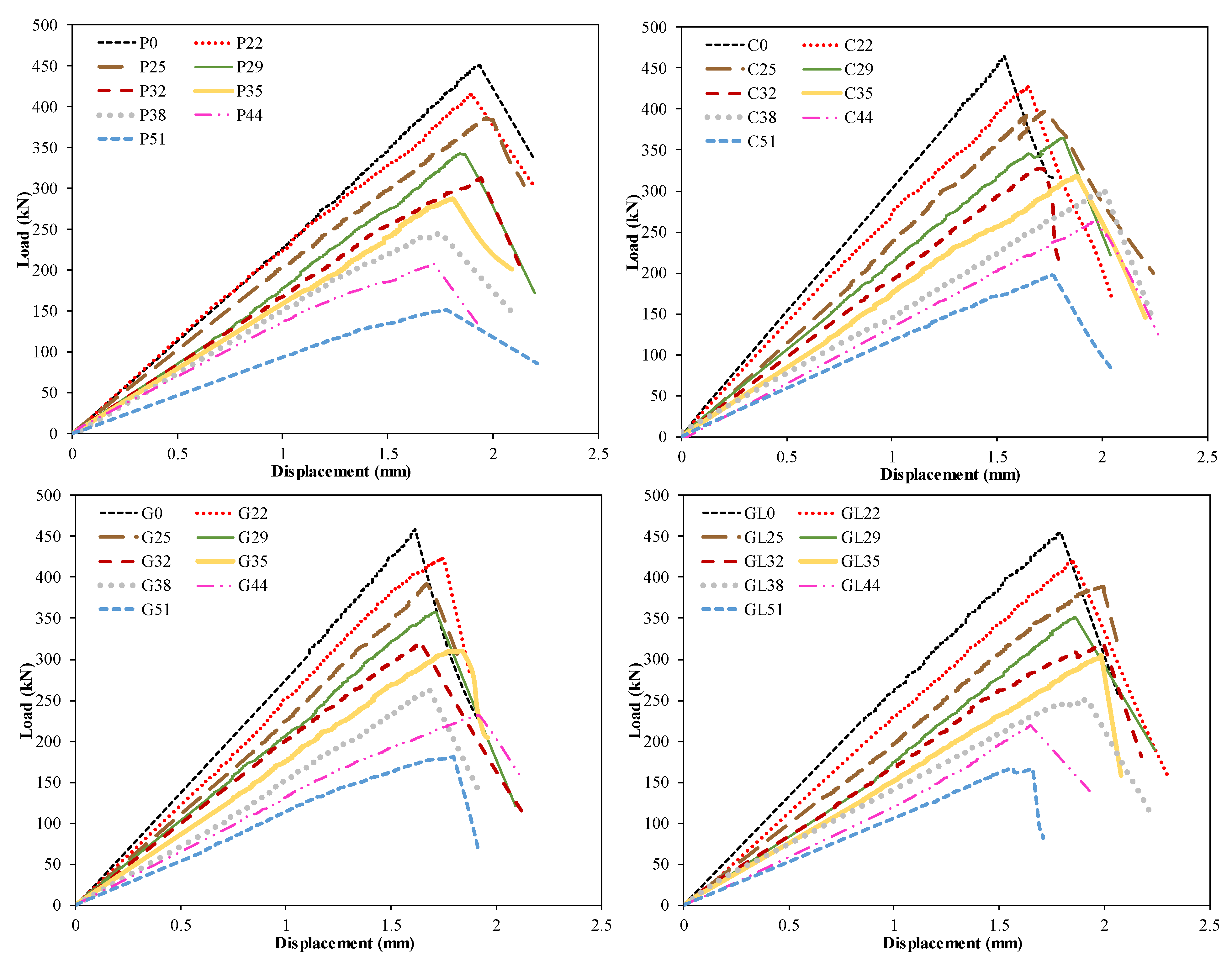
- The effect of CFRP and GFRP strengthening for the pultruded box columns, within which the openings were under a compression load, was examined. From the experimental results obtained in the study, it is seen that there is no need to take any precaution for low-strength fibers (300 gr/m2 GFRP) used for pultruded columns with openings, provided that the D/W ratios do not exceed 0.68. However, it was observed that the decrease in load-bearing capacity and the decrease in initial stiffness coincided with the increase in the hole diameters. It is observed that the CFRP (C), GFRP (G), and GFRP (GL)-strengthening methods can restore the pultruded column to the reference capacity level, especially for the columns where the D/W ratio is between 0.29 and 0.68. It can be concluded that all strengthening applications will be effective up to a certain D/W ratio. After the experiment, the damage modes occurring in CFRP (C), GFRP (G), and GFRP (GL) applications were detected in the micro damage analysis and ranked according to the order of damage development. According to this analysis, the damages that occurred were fiber bundles debonding, delamination between fiber and pultruded column in the direction of the fiber, splitting, web–flange junction failure, and fiber breakages.
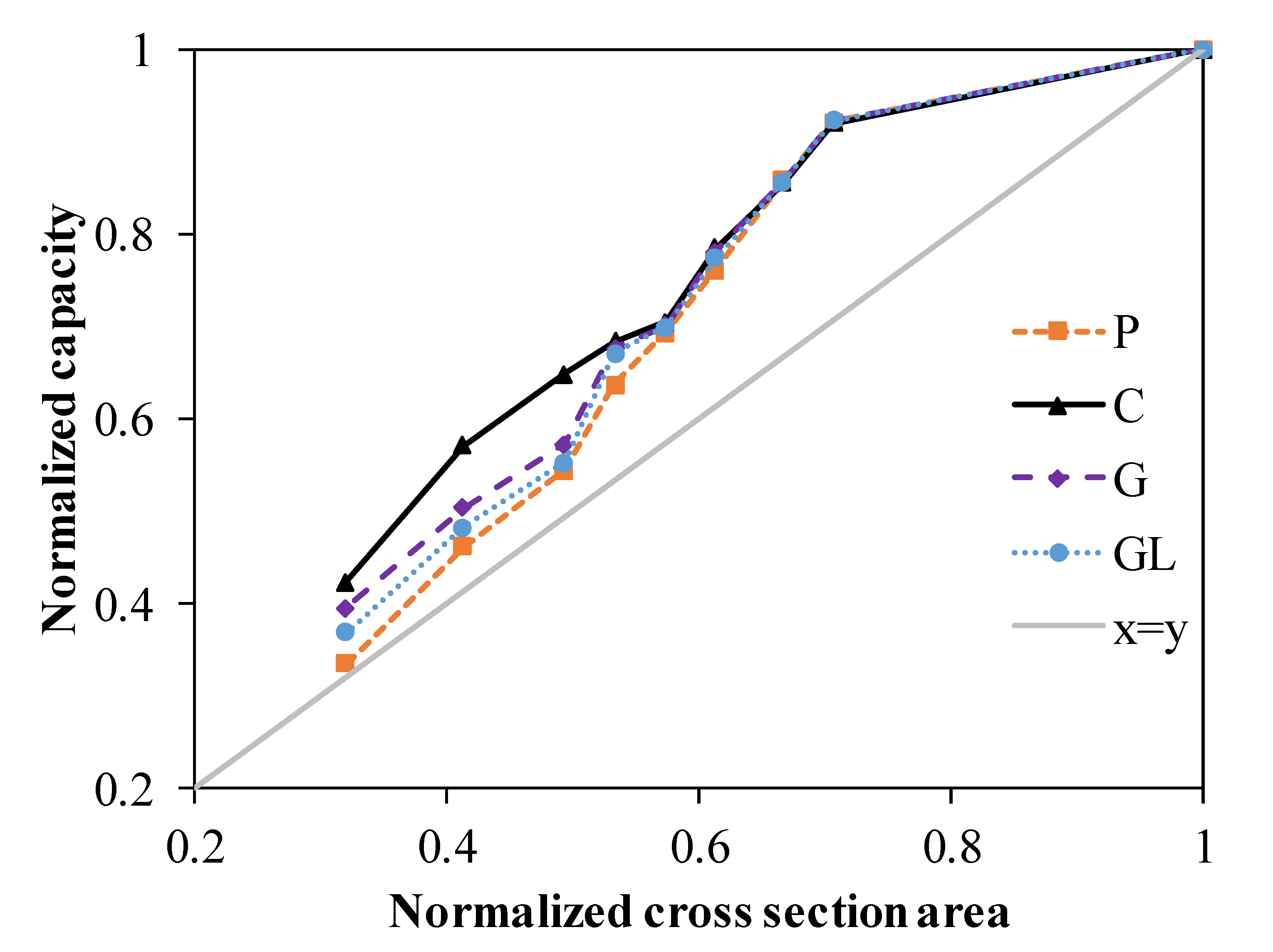
- The pultruded profiles with openings can compensate the reduction in load-bearing capacity with holes up to a 0.39 D/W ratio. The capacity significantly drops after a D/W ratio of 0.39. Moreover, the pultruded profile with CFRP wrapping is more likely to compensate the capacity compared to other wrappings.
Author Contributions
Funding
Institutional Review Board Statement
Data Availability Statement
Conflicts of Interest
References
- Nunes, F.; Silvestre, N.; Correia, J.R. Progressive damage analysis of web crippling of GFRP pultruded I-sections. J. Compos. Constr. 2017, 21, 04016104. [Google Scholar] [CrossRef]
- Vedernikov, A.; Safonov, A.; Tucci, F.; Carlone, P.; Akhatov, I. Pultruded materials and structures: A review. J. Compos. Mater. 2020, 54, 4081–4117. [Google Scholar] [CrossRef]
- Vedernikov, A.; Tucci, F.; Carlone, P.; Gusev, S.; Konev, S.; Firsov, D.; Akhatov, I.; Safonov, A. Effects of pulling speed on structural performance of L-shaped pultruded profiles. Compos. Struct. 2021, 255, 112967. [Google Scholar] [CrossRef]
- Özkılıç, Y.O.; Madenci, E.; Gemi, L. Tensile and compressive behaviors of the pultruded GFRP lamina. Turk. J. Eng. 2020, 4, 169–175. [Google Scholar]
- Madenci, E.; Özkılıç, Y.O.; Gemi, L. Experimental and theoretical investigation on flexure performance of pultruded GFRP composite beams with damage analyses. Compos. Struct. 2020, 242, 112162. [Google Scholar] [CrossRef]
- Madenci, E.; Özkılıç, Y.O.; Gemi, L. Buckling and free vibration analyses of pultruded GFRP laminated composites: Experimental, numerical and analytical investigations. Compos. Struct. 2020, 254, 112806. [Google Scholar] [CrossRef]
- Madenci, E.; Özkılıç, Y.O.; Gemi, L. Theoretical investigation on static analysis of pultruded GFRP composite beams. Acad. Platf. J. Eng. Sci. 2020, 8, 483–490. [Google Scholar]
- Wang, W.; Xian, G.; Li, H. Surface modification of ramie fibers with silanized CNTs through a simple spray-coating method. Cellulose 2019, 26, 8165–8178. [Google Scholar] [CrossRef]
- Gemi, L.; Madenci, E.; Özkılıç, Y.O.; Yazman, Ş.; Safonov, A. Effect of Fiber Wrapping on Bending Behavior of Reinforced Concrete Filled Pultruded GFRP Composite Hybrid Beams. Polymers 2022, 14, 3740. [Google Scholar] [CrossRef]
- Gemi, L.; Madenci, E.; Özkılıç, Y.O. Experimental, analytical and numerical investigation of pultruded GFRP composite beams infilled with hybrid FRP reinforced concrete. Eng. Struct. 2021, 244, 112790. [Google Scholar] [CrossRef]
- Vedernikov, A.; Gemi, L.; Madenci, E.; Onuralp Özkılıç, Y.; Yazman, Ş.; Gusev, S.; Sulimov, A.; Bondareva, J.; Evlashin, S.; Konev, S.; et al. Effects of high pulling speeds on mechanical properties and morphology of pultruded GFRP composite flat laminates. Compos. Struct. 2022, 301, 116216. [Google Scholar] [CrossRef]
- Zaghloul, M.M.Y.; Zaghloul, M.Y.M.; Zaghloul, M.M.Y. Experimental and modeling analysis of mechanical-electrical behaviors of polypropylene composites filled with graphite and MWCNT fillers. Polym. Test. 2017, 63, 467–474. [Google Scholar] [CrossRef]
- Zaghloul, M.M.Y.; Mohamed, Y.S.; El-Gamal, H. Fatigue and tensile behaviors of fiber-reinforced thermosetting composites embedded with nanoparticles. J. Compos. Mater. 2019, 53, 709–718. [Google Scholar] [CrossRef]
- Zaghloul, M.M.Y.; Zaghloul, M.M.Y. Influence of flame retardant magnesium hydroxide on the mechanical properties of high density polyethylene composites. J. Reinf. Plast. Compos. 2017, 36, 1802–1816. [Google Scholar] [CrossRef]
- Zaghloul, M.M.Y.M. Mechanical properties of linear low-density polyethylene fire-retarded with melamine polyphosphate. J. Appl. Polym. Sci. 2018, 135, 46770. [Google Scholar] [CrossRef]
- Fuseini, M.; Zaghloul, M.M.Y. Qualitative and statistical approaches of the electrophoretic deposition kinetics of polyaniline copper coating. Prog. Org. Coat. 2022, 171, 107015. [Google Scholar] [CrossRef]
- Mahmoud Zaghloul, M.Y.; Yousry Zaghloul, M.M.; Yousry Zaghloul, M.M. Developments in polyester composite materials—An in-depth review on natural fibres and nano fillers. Compos. Struct. 2021, 278, 114698. [Google Scholar] [CrossRef]
- Li, C.; Xian, G.; Li, H. Combined effects of temperature, hydraulic pressure and salty concentration on the water uptake and mechanical properties of a carbon/glass fibers hybrid rod in salty solutions. Polym. Test. 2019, 76, 19–32. [Google Scholar] [CrossRef]
- Humeau, C.; Davies, P.; Jacquemin, F. Moisture diffusion under hydrostatic pressure in composites. Mater. Des. 2016, 96, 90–98. [Google Scholar] [CrossRef]
- Zhao, X.; Wang, X.; Wu, Z.; Zhu, Z. Fatigue behavior and failure mechanism of basalt FRP composites under long-term cyclic loads. Int. J. Fatigue 2016, 88, 58–67. [Google Scholar] [CrossRef]
- Rezazadeh, M.; Carvelli, V. A damage model for high-cycle fatigue behavior of bond between FRP bar and concrete. Int. J. Fatigue 2018, 111, 101–111. [Google Scholar] [CrossRef]
- Li, C.; Yin, X.; Wang, Y.; Zhang, L.; Zhang, Z.; Liu, Y.; Xian, G. Mechanical property evolution and service life prediction of pultruded carbon/glass hybrid rod exposed in harsh oil-well condition. Compos. Struct. 2020, 246, 112418. [Google Scholar] [CrossRef]
- Li, C.; Guo, R.; Xian, G.; Li, H. Innovative compound-type anchorage system for a large-diameter pultruded carbon/glass hybrid rod for bridge cable. Mater. Struct. 2020, 53, 73. [Google Scholar] [CrossRef]
- Nie, X.; Zhang, S.S.; Teng, J.G.; Chen, G. Experimental study on RC T-section beams with an FRP-strengthened web opening. Compos. Struct. 2018, 185, 273–285. [Google Scholar] [CrossRef]
- Salih, R.; Zhou, F.; Abbas, N.; Khan Mastoi, A. Experimental investigation of reinforced concrete beam with openings strengthened using FRP sheets under cyclic load. Materials 2020, 13, 3127. [Google Scholar] [CrossRef]
- Chung, K.F.; Liu, T.C.H.; Ko, A.C.H. Investigation on Vierendeel mechanism in steel beams with circular web openings. J. Constr. Steel Res. 2001, 57, 467–490. [Google Scholar] [CrossRef]
- Nie, X.; Zhang, S.; Gao, Z.; Zeng, Z. A review on the behaviour of reinforced concrete beams with fibre-reinforced polymer-strengthened web openings. Adv. Struct. Eng. 2022, 25, 426–450. [Google Scholar] [CrossRef]
- Osman, B.H.; Wu, E.; Ji, B.; SAbdelgader, A.M. A state of the art review on reinforced concrete beams with openings retrofitted with FRP. Int. J. Adv. Struct. Eng. 2016, 8, 253–267. [Google Scholar] [CrossRef]
- Soudki, K.; El-Salakawy, E.; Craig, B. Behavior of CFRP strengthened reinforced concrete beams in corrosive environment. J. Compos. Constr. 2007, 11, 291–298. [Google Scholar] [CrossRef]
- Elsanadedy, H.; Al-Salloum, Y.; Al-Zaheri, Z.; Alsayed, S.; Abbas, H. Behavior and design aspects of FRP-strengthened URM walls under out-of-plane loading. J. Compos. Constr. 2016, 20, 04016048. [Google Scholar] [CrossRef]
- Elsanadedy, H.; Abbas, H.; Al-Salloum, Y.; Almusallam, T. Prediction of intermediate crack debonding strain of externally bonded FRP laminates in RC beams and one-way slabs. J. Compos. Constr. 2014, 18, 04014008. [Google Scholar] [CrossRef]
- Özkılıç, Y.O.; Aksoylu, C.; Yazman, Ş.; Gemi, L.; Arslan, M.H. Behavior of CFRP-strengthened RC beams with circular web openings in shear zones: Numerical study. Structures 2022, 41, 1369–1389. [Google Scholar] [CrossRef]
- Gemi, L.; Alsdudi, M.; Aksoylu, C.; Yazman, S.; Ozkilic, Y.O.; Arslan, M.H. Optimum amount of CFRP for strengthening shear deficient reinforced concrete beams. Steel Compos. Struct. 2022, 43, 735–757. [Google Scholar]
- Arslan, M.H.; Yazman, Ş.; Hamad, A.A.; Aksoylu, C.; Özkılıç, Y.O.; Gemi, L. Shear strengthening of reinforced concrete T-beams with anchored and non-anchored CFRP fabrics. Structures 2022, 39, 527–542. [Google Scholar] [CrossRef]
- Özkılıç, Y.O.; Yazman, Ş.; Aksoylu, C.; Arslan, M.H.; Gemi, L. Numerical investigation of the parameters influencing the behavior of dapped end prefabricated concrete purlins with and without CFRP strengthening. Constr. Build. Mater. 2021, 275, 122173. [Google Scholar] [CrossRef]
- Aksoylu, C.; Özkılıç, Y.O.; Yazman, Ş.; Gemi, L.; Arslan, M.H. Experimental and Numerical Investigation of Load Bearing Capacity of Thinned End Precast Purlin Beams and Solution Proposals. Tek. Dergi 2021, 32, 10823–10858. [Google Scholar]
- Aksoylu, C.; Yazman, Ş.; Özkılıç, Y.O.; Gemi, L.; Arslan, M.H. Experimental analysis of reinforced concrete shear deficient beams with circular web openings strengthened by CFRP composite. Compos. Struct. 2020, 249, 112561. [Google Scholar] [CrossRef]
- Aksoylu, C.; Özkılıç, Y.O.; Arslan, M.H. Damages on prefabricated concrete dapped-end purlins due to snow loads and a novel reinforcement detail. Eng. Struct. 2020, 225, 111225. [Google Scholar] [CrossRef]
- Elsanadedy, H.M.; Al-Salloum, Y.A.; Almusallam, T.H.; Alshenawy, A.O.; Abbas, H. Experimental and numerical study on FRP-upgraded RC beams with large rectangular web openings in shear zones. Constr. Build. Mater. 2019, 194, 322–343. [Google Scholar] [CrossRef]
- Abdalla, H.; Torkey, A.; Haggag, H.; Abu-Amira, A. Design against cracking at openings in reinforced concrete beams strengthened with composite sheets. Compos. Struct. 2003, 60, 197–204. [Google Scholar] [CrossRef]
- Pimanmas, A. Strengthening R/C beams with opening by externally installed FRP rods: Behavior and analysis. Compos. Struct. 2010, 92, 1957–1976. [Google Scholar] [CrossRef]
- Fatehi Makki, R.; Talib Jassem, A.; Abd Al-Latef Jassem, H. Behavior of reactive-powder concrete deep beams with CFRP-strengthened openings. Pract. Period. Struct. Des. Constr. 2019, 24, 04019016. [Google Scholar] [CrossRef]
- Arabzadeh, A.; Karimizadeh, H. Experimental study of RC deep beams with opening and FRP composites installed by means of EBR and EBROG methods. Constr. Build. Mater. 2019, 208, 780–791. [Google Scholar] [CrossRef]
- Allawi, A.A.; Oukaili, N.K.; Jasim, W.A. Strength compensation of deep beams with large web openings using carbon fiber–reinforced polymer sheets. Adv. Struct. Eng. 2021, 24, 165–182. [Google Scholar] [CrossRef]
- Rahim, N.I.; Mohammed, B.S.; Al-Fakih, A.; Wahab, M.; Liew, M.; Anwar, A.; Amran, Y.H. Strengthening the structural behavior of web openings in RC deep beam using CFRP. Materials 2020, 13, 2804. [Google Scholar] [CrossRef]
- Almusallam, T.; Al-Salloum, Y.; Elsanadedy, H.; Alshenawy, A.; Iqbal, R. Behavior of FRP-strengthened RC beams with large rectangular web openings in flexure zones: Experimental and numerical study. Int. J. Concr. Struct. Mater. 2018, 12, 47. [Google Scholar] [CrossRef]
- Hemzah, S.A.; Alyhya, W.S.; Hassan, S.A. Experimental investigation for structural behaviour of self-compacting reinforced concrete hollow beams with in-place circular openings strengthened with CFRP laminates. Structures 2020, 24, 99–106. [Google Scholar] [CrossRef]
- Mansur, M.; Tan, K.-H.; Wei, W. Effects of creating an opening in existing beams. Struct. J. 1999, 96, 899–905. [Google Scholar]
- Teng, J.G.; Zhang, S.S.; Dai, J.; Chen, J. Three-dimensional meso-scale finite element modeling of bonded joints between a near-surface mounted FRP strip and concrete. Comput. Struct. 2013, 117, 105–117. [Google Scholar] [CrossRef]
- Nie, X.; Zhang, S.; Chen, G.; Yu, T. Strengthening of RC beams with rectangular web openings using externally bonded FRP: Numerical simulation. Compos. Struct. 2020, 248, 112552. [Google Scholar] [CrossRef]
- Nie, X.; Zhang, S.; Yu, T. Behaviour of RC beams with a fibre-reinforced polymer (FRP)-strengthened web opening. Compos. Struct. 2020, 252, 112684. [Google Scholar] [CrossRef]


| Property | Mean Value (MPa) |
|---|---|
| Longitudinal tensile modulus of elasticity | 23,000 |
| Transverse tensile modulus of elasticity | 7000 |
| Longitudinal tensile strength | 240 |
| Transverse tensile strength | 50 |
| Longitudinal compressive strength | 150 |
| Transverse compressive strength | 70 |
| Shear strength | 25 |
| CFRP Strip Properties (800 gr/m2) | Values |
|---|---|
| Thickness (mm) | 0.85 |
| Tensile strength (GPa) | 4.4 |
| Modulus of elasticity (GPa) | 235 |
| Rupture strain (%) | 1.87 |
| GFRP strip properties (1200 gr/m2) | Values |
| Thickness (mm) | 1.2 |
| Tensile strength (GPa) | 3.5 |
| Modulus of elasticity (GPa) | 80 |
| Rupture strain (%) | 4.37 |
| GFRP strip properties (300 gr/m2) | Values |
| Thickness (mm) | 0.3 |
| Tensile strength (GPa) | 0.586 |
| Modulus of elasticity (GPa) | 31.2 |
| Rupture strain (%) | 1.91 |
| Epoxy + Hardener (F-1564 + F-3486) | Values |
| Tensile strength (GPa) | 0.055 |
| Modulus of elasticity (GPa) | 2.090 |
| Rupture strain (%) | 4.06 ± 1.27 |
| Hole Size | D/W | P (kN) | Reduct. % | C (kN) | Reduct. % | G (kN) | Reduct. % | GL (kN) | Reduct. % |
|---|---|---|---|---|---|---|---|---|---|
| 0 | 0 | 450.6 | 1 | 464.9 | 1 | 458.6 | 1 | 454.5 | 1 |
| 22 | 0.29 | 414.9 | 7.9 | 427.5 | 8.04 | 422.8 | 7.8 | 418.9 | 7.8 |
| 25 | 0.32 | 386.5 | 14.22 | 397.1 | 14.58 | 392.5 | 14.41 | 389.3 | 14.34 |
| 29 | 0.39 | 342.9 | 23.90 | 364.9 | 21.51 | 357.6 | 22.02 | 351.1 | 22.75 |
| 32 | 0.42 | 312.4 | 30.67 | 327.6 | 29.53 | 320.8 | 30.04 | 317.6 | 30.12 |
| 35 | 0.46 | 286.9 | 36.32 | 317.8 | 31.64 | 310.1 | 32.38 | 305.1 | 32.87 |
| 38 | 0.50 | 245.3 | 45.56 | 301.1 | 35.23 | 262.3 | 42.80 | 251.1 | 44.75 |
| 44 | 0.58 | 207.8 | 53.88 | 265.1 | 42.97 | 231 | 49.63 | 219.2 | 51.77 |
| 51 | 0.68 | 151.2 | 66.44 | 196.9 | 57.64 | 181.1 | 60.51 | 167.3 | 63.19 |
| Test Specimens | Damage Modes | Explanation |
|---|---|---|
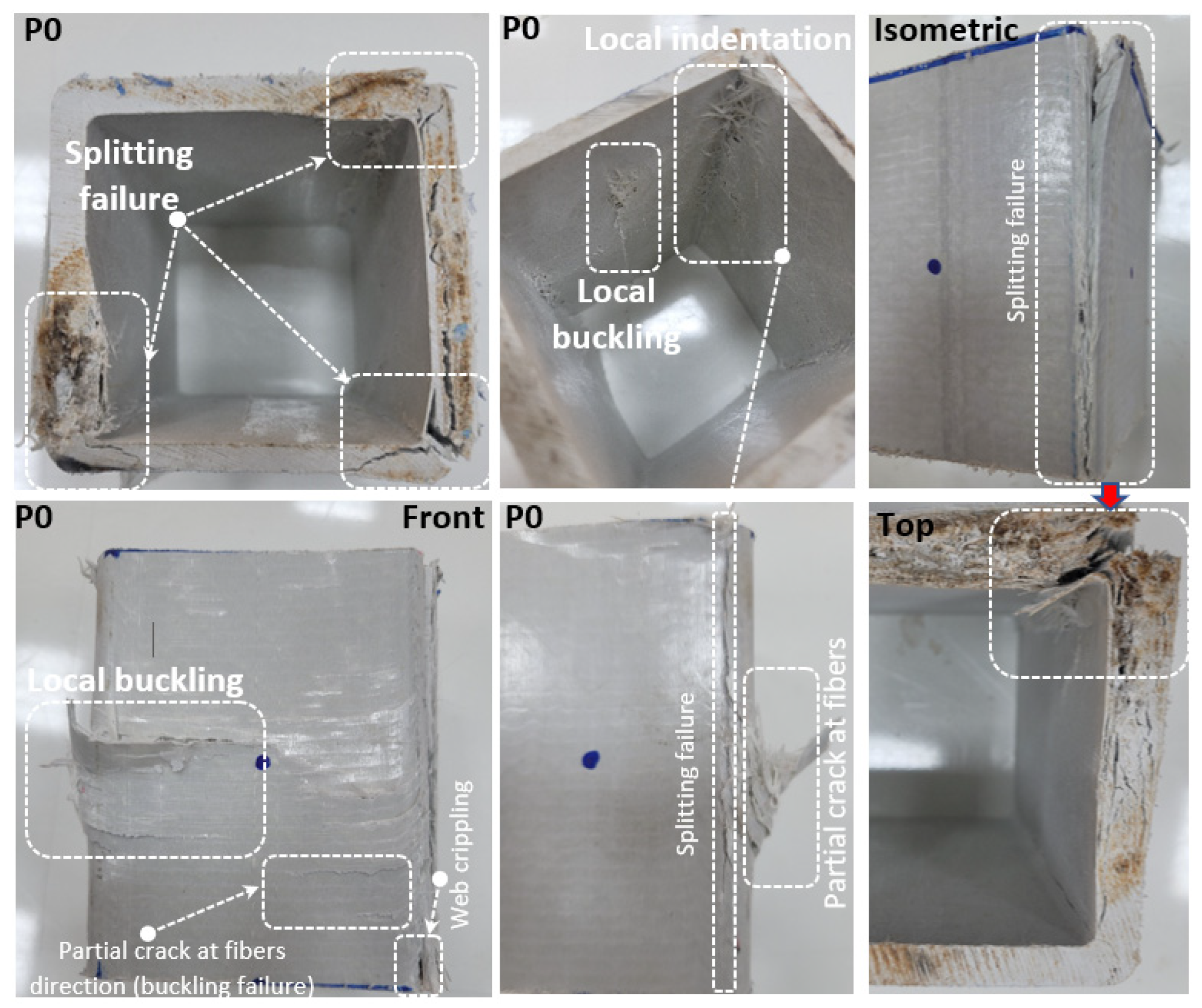
| P0 | Splitting failure Local buckling Local indentation Web Crippling | Splitting failure was observed on web–flange junction. In addition, local buckling occurred in the middle of the profile height, with the effect of compression. Local indentation was observed in the upper region where the load was applied, and web crippling (crushing behavior) was observed in the lower region. |
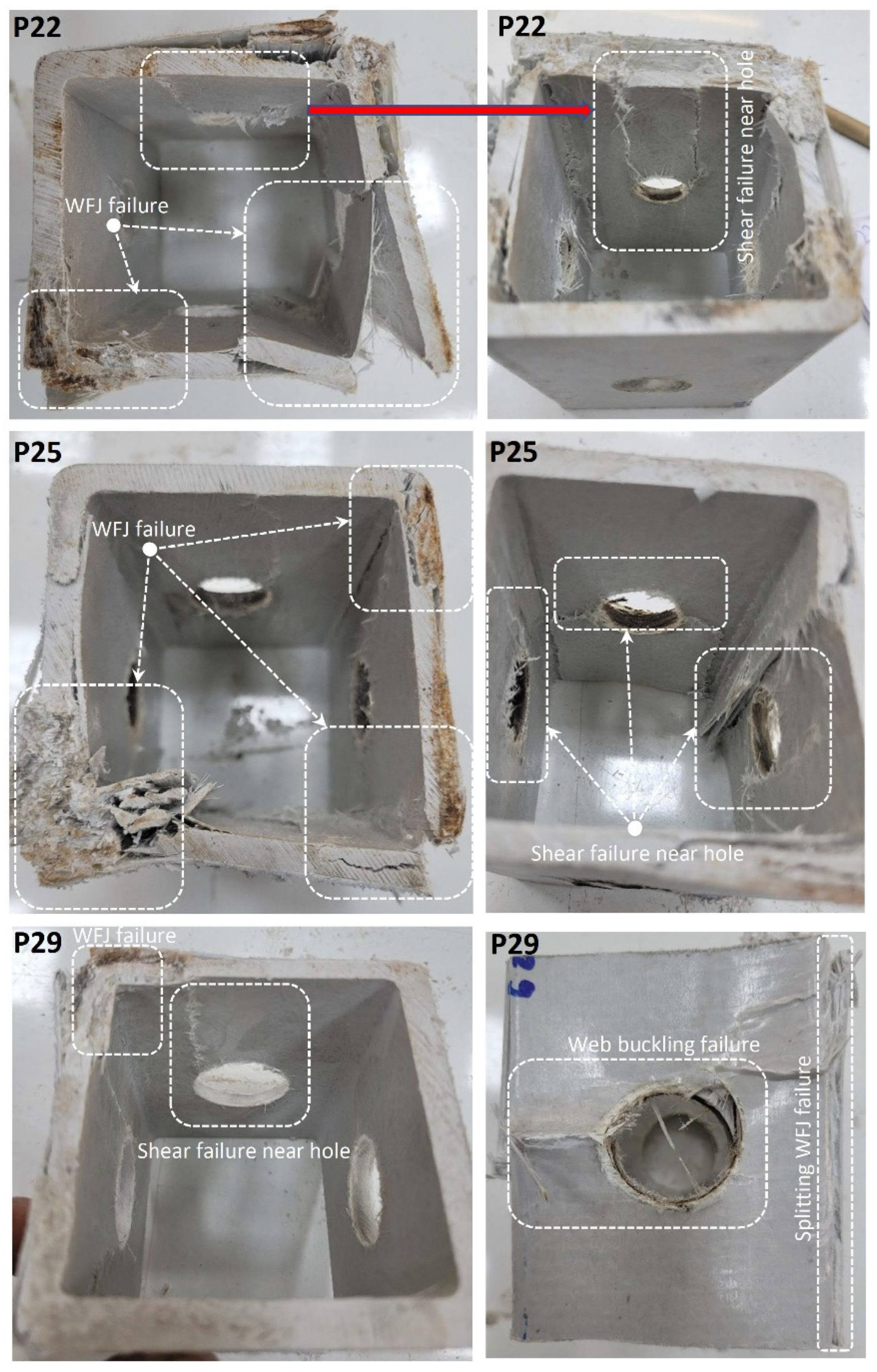
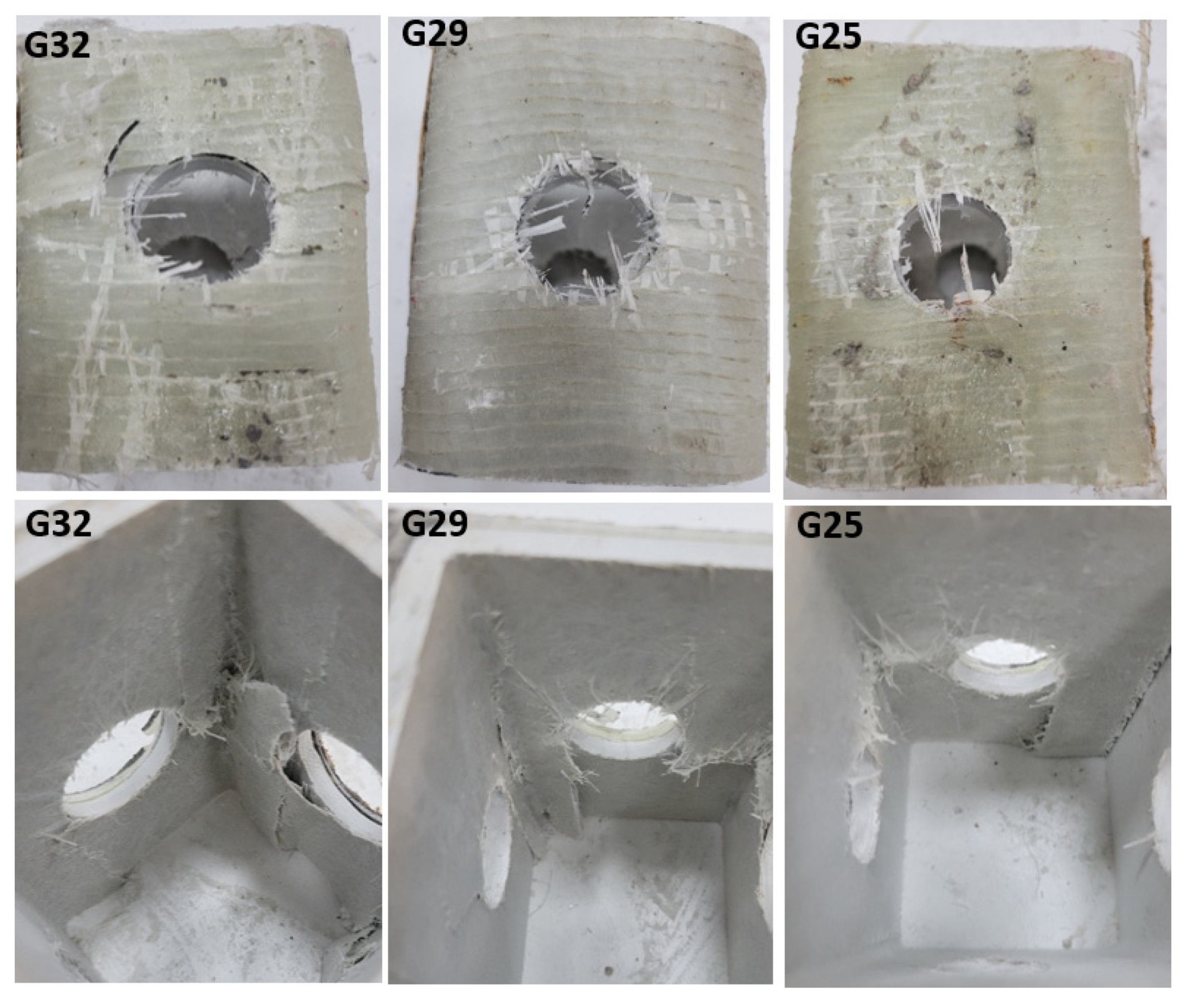
| P22-P25-P29-P32 | WFJ failure Shear failure near hole Web buckling failure | Shear damage was observed starting around the hole and progressing to the profile height. In addition, splitting damage occurred at the profile corner points. Web buckling failure with shear damage around the hole was observed in P29. |
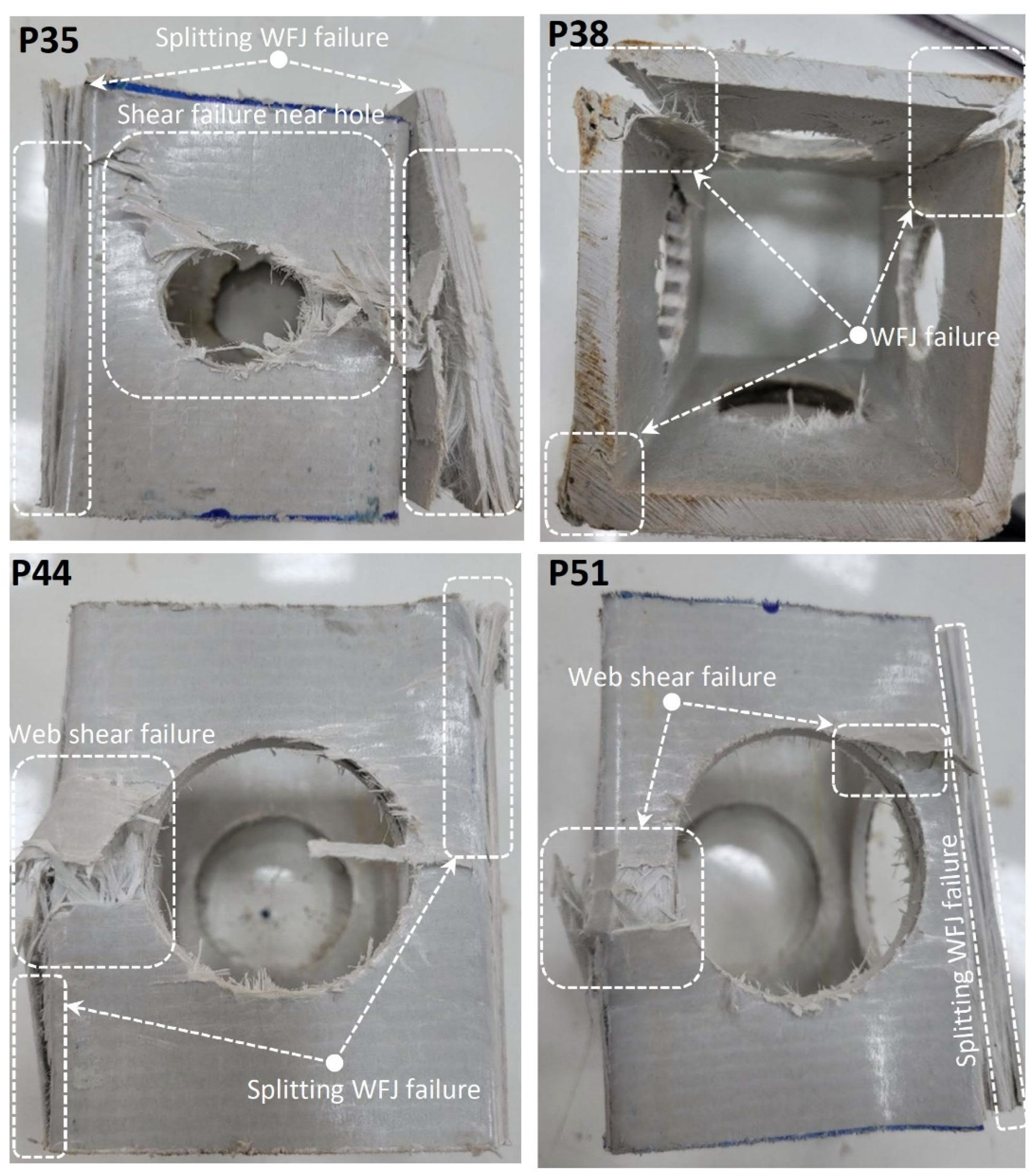
| P35-P38-P44-P51 | WFJ failure Web shear failure Shear failure near hole | While web buckling with cracking at the mid was observed in specimens with a D/W ratio below 0.46 (P35 specimen), direct shear damage was observed in specimens above this ratio. |
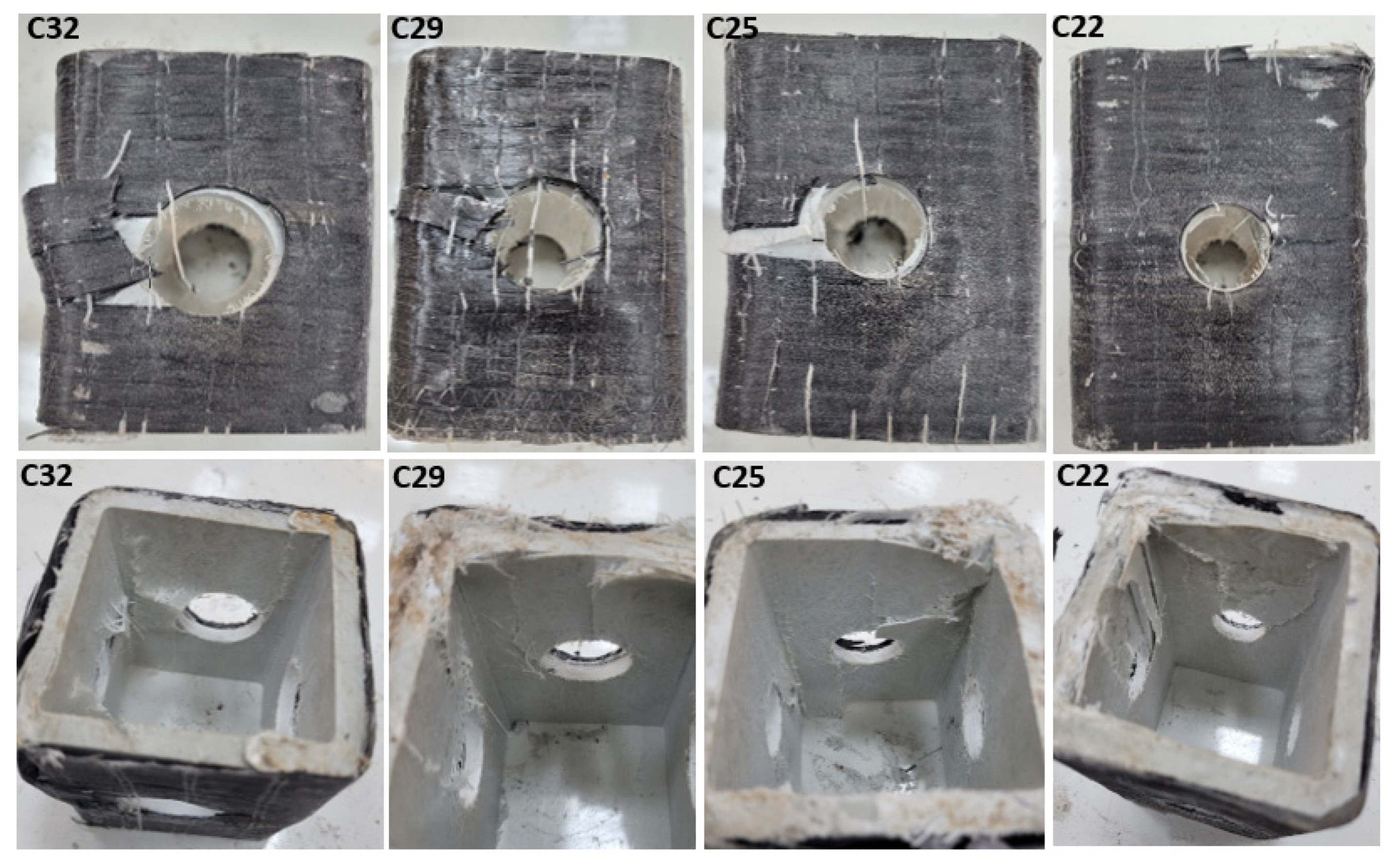
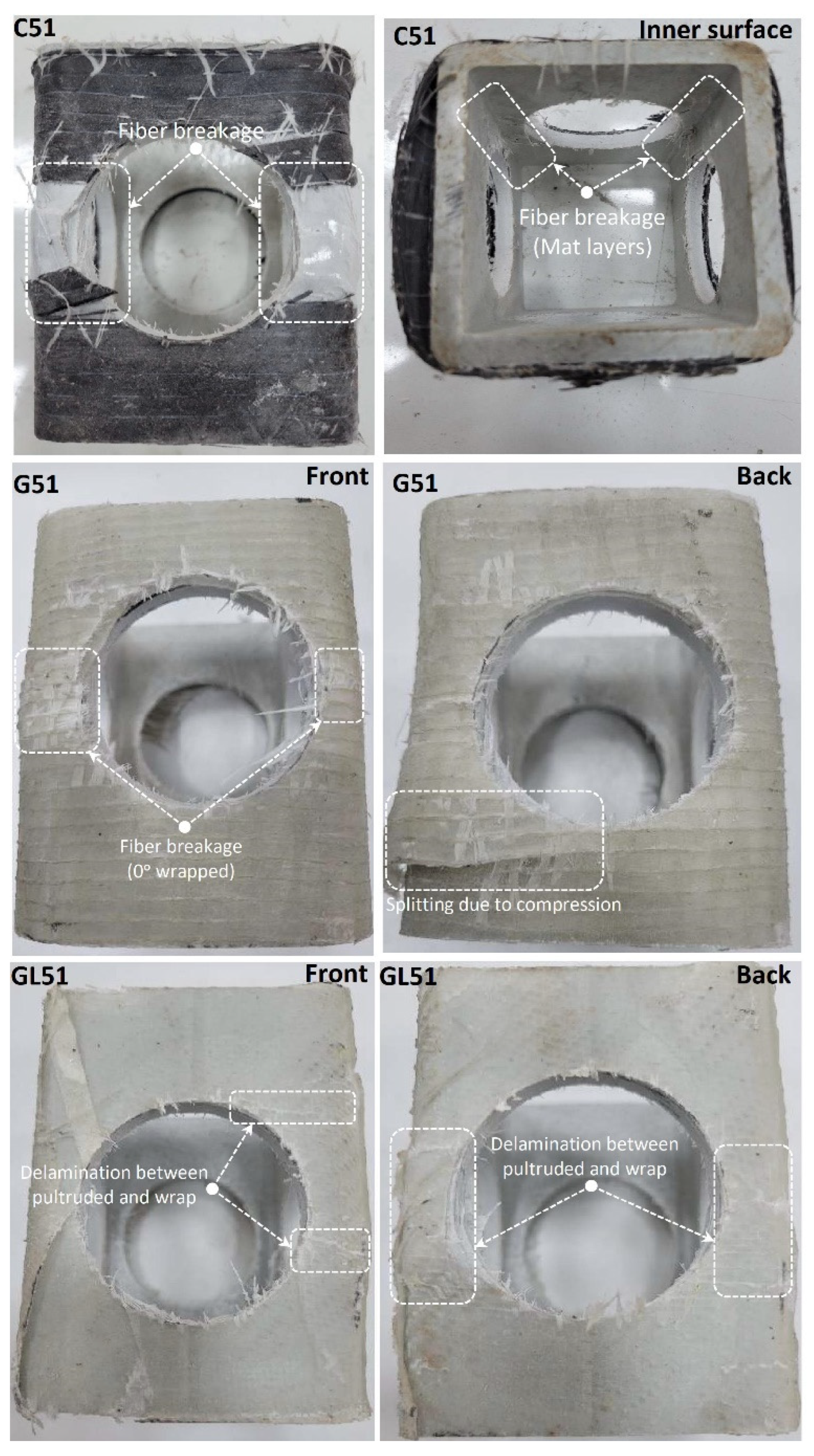
| C51-G51-GL51 | Fiber breakage Splitting due to compression Delamination between pultruded and wrap | WFJ failure prevented in each strengthening application. Fiber breakage was observed around the hole in specimens C51 and G51, while additional splitting damage was observed in specimen G51. Moreover, delamination was observed around the hole in the GL51. |
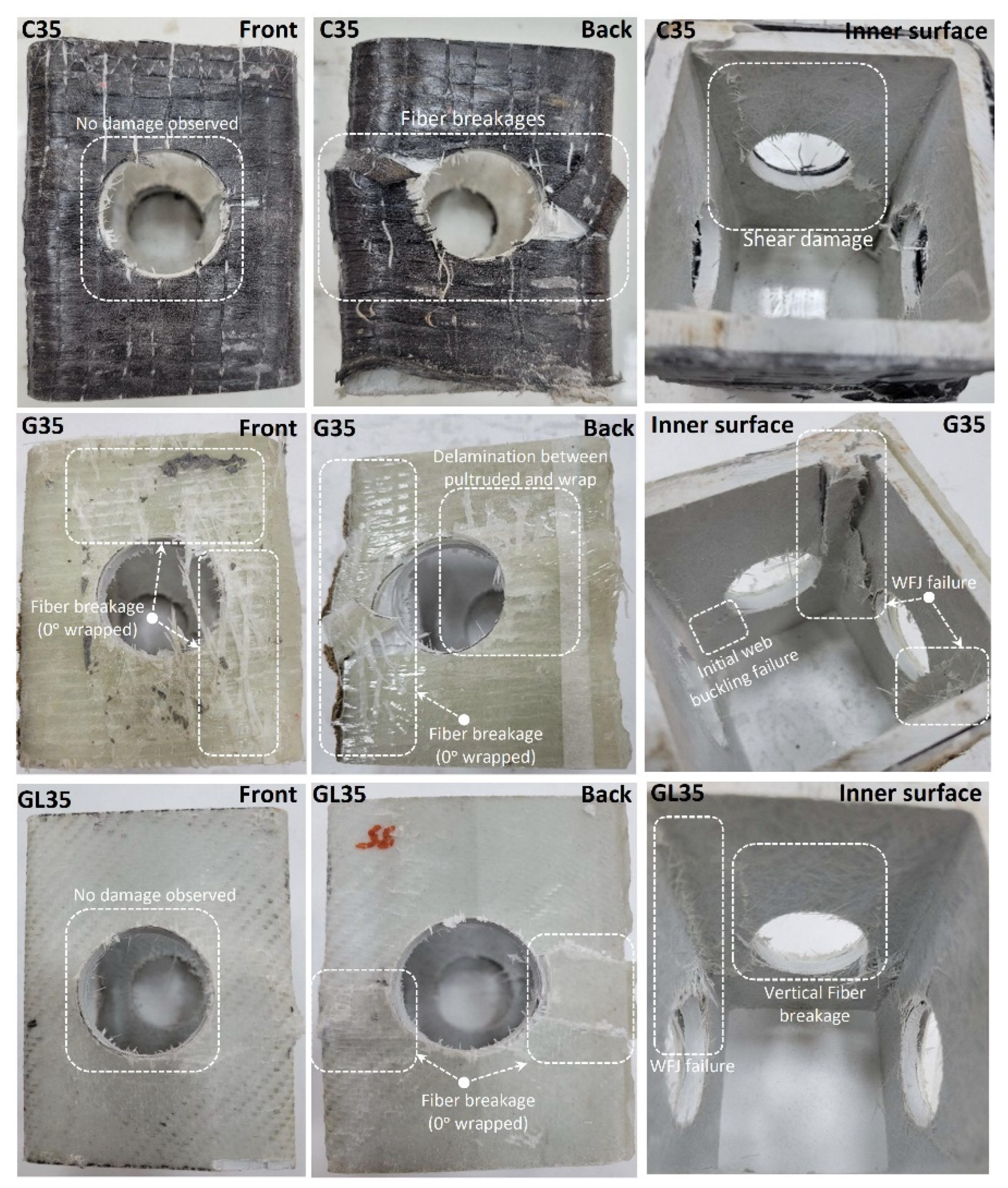
| C35-G35-GL35 | Fiber breakage Shear damage near hole Delamination between pultruded and wrap | GL formed a better adhesion interface, resulting in less internal surface damage. Fiber damage observed in C- and G-type reinforcements led to an increase in internal surface damage. |
Publisher’s Note: MDPI stays neutral with regard to jurisdictional claims in published maps and institutional affiliations. |
© 2022 by the authors. Licensee MDPI, Basel, Switzerland. This article is an open access article distributed under the terms and conditions of the Creative Commons Attribution (CC BY) license (https://creativecommons.org/licenses/by/4.0/).
Share and Cite
Aksoylu, C.; Özkılıç, Y.O.; Madenci, E.; Safonov, A. Compressive Behavior of Pultruded GFRP Boxes with Concentric Openings Strengthened by Different Composite Wrappings. Polymers 2022, 14, 4095. https://doi.org/10.3390/polym14194095
Aksoylu C, Özkılıç YO, Madenci E, Safonov A. Compressive Behavior of Pultruded GFRP Boxes with Concentric Openings Strengthened by Different Composite Wrappings. Polymers. 2022; 14(19):4095. https://doi.org/10.3390/polym14194095
Chicago/Turabian StyleAksoylu, Ceyhun, Yasin Onuralp Özkılıç, Emrah Madenci, and Alexander Safonov. 2022. "Compressive Behavior of Pultruded GFRP Boxes with Concentric Openings Strengthened by Different Composite Wrappings" Polymers 14, no. 19: 4095. https://doi.org/10.3390/polym14194095
APA StyleAksoylu, C., Özkılıç, Y. O., Madenci, E., & Safonov, A. (2022). Compressive Behavior of Pultruded GFRP Boxes with Concentric Openings Strengthened by Different Composite Wrappings. Polymers, 14(19), 4095. https://doi.org/10.3390/polym14194095