
Embossing Lines and Dots Geometry Effect on the Key Tissue Paper Properties with Finite Element Method Analysis

 ,
, 
 ,
,  ,
,  and
and 
Abstract
:1. Introduction
2. Materials and Methods
2.1. Materials
2.2. Methods
2.3. Finite Element Method (FEM)
3. Results
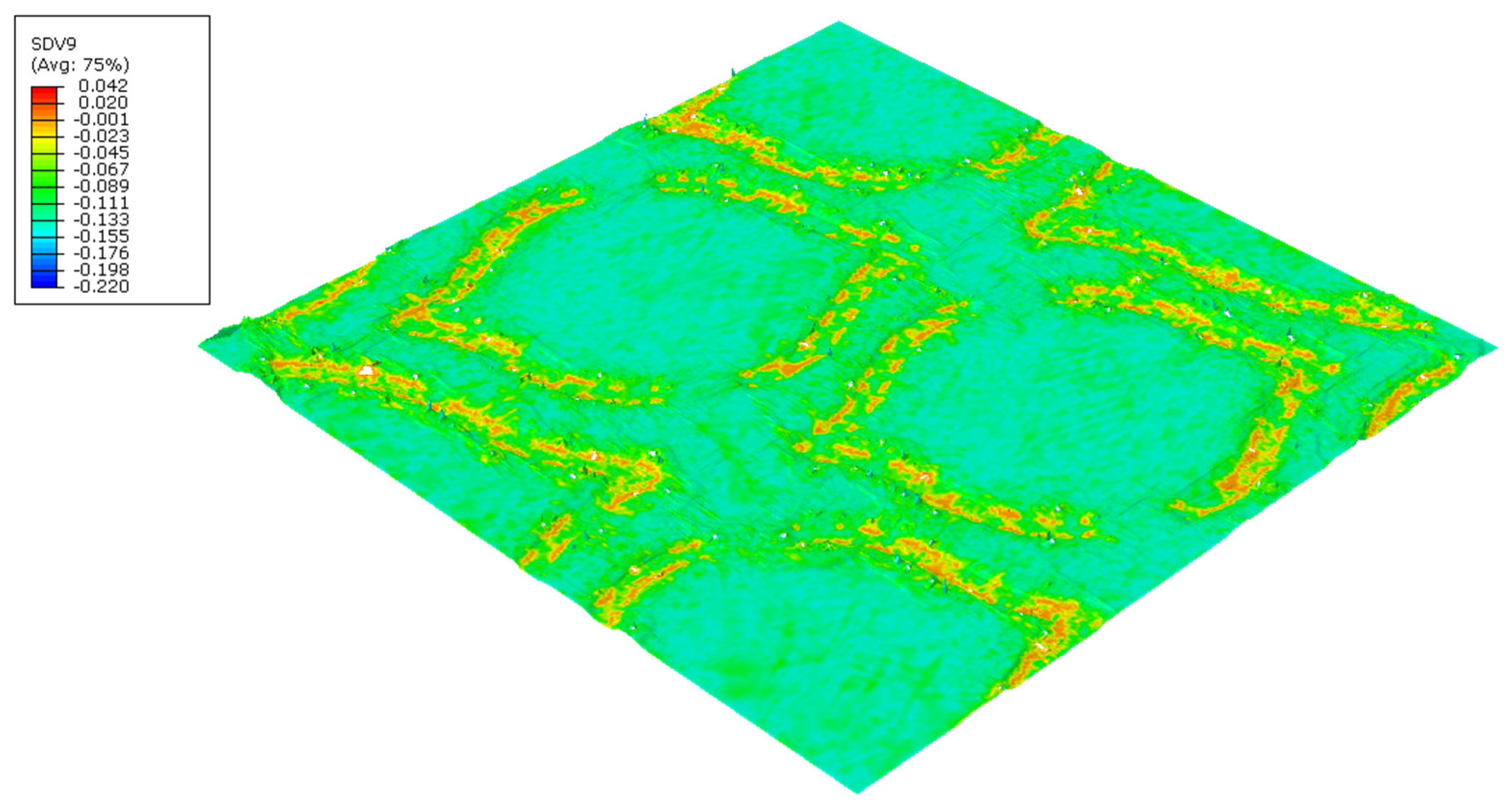
Finite Element Method (FEM)
4. Discussion
5. Conclusions
Author Contributions
Funding
Institutional Review Board Statement
Informed Consent Statement
Data Availability Statement
Acknowledgments
Conflicts of Interest
References
- Delić, G.; Vladić, G.; Pál, M.; Banjanin, B.; Dedijer, S. Performance evaluation of paper embossing tools produced by fused deposition modelling additive manufacturing technology. J. Graph. Eng. Des. 2017, 8, 47–54. [Google Scholar] [CrossRef]
- Spina, R.; Cavalcante, B. Characterizing Materials and Processes Used on Paper Tissue Converting Lines. Mater. Today Commun. 2018, 17, 427–437. [Google Scholar] [CrossRef]
- Biagiotti, M. Tissue Embossing Developments | The Tissue Story. 2017. Available online: https://www.tissuestory.com/2017/11/21/tissue-embossing-developments/ (accessed on 8 January 2019).
- Wilhelm, L. Embossing Roll and Embossed Substract. WO2005065928A1, 30 June 2005. [Google Scholar]
- Pál, M.; Banjanin, B.; Dedijer, S.; Vladić, G.; Bošnjaković, G. Preliminary analysis of image processing-based evaluation of embossing quality. In Proceedings of the Tenth International Symposium GRID 2020, Kashan, Iran, 16–17 December 2020; University of Novi Sad, Faculty of Technical Sciences, Department of Graphic Engineering and Design: Novi-Sad, Serbia, 2020; pp. 269–279. [Google Scholar] [CrossRef]
- Khan, A.A. Development of Model to Simulate Embossing of Tissue Paper: Effect of Embossing on Mechanical Performance of Tissue. Thesis for Master of Science (M.Sc.) in Engineering Mechanics, KTH Royal Institute of Technology. 2021. Available online: https://www.diva-portal.org/smash/get/diva2:1590118/FULLTEXT01.pdf (accessed on 14 November 2021).
- Vieira, J.C.; Mendes, A.d.O.; Ribeiro, M.L.; Vieira, A.C.; Carta, A.M.; Fiadeiro, P.T.; Costa, A.P. Embossing Pressure Effect on Mechanical and Softness Properties of Industrial Base Tissue Papers with Finite Element Method Validation. Materials 2022, 15, 4324. [Google Scholar] [CrossRef] [PubMed]
- Vieira, J.C.; Mendes, A.d.O.; Ribeiro, M.L.; Vieira, A.C.; Carta, A.M.; Fiadeiro, P.T.; Costa, A.P. FEM Analysis Validation of Rubber Hardness Impact on Mechanical and Softness Properties of Embossed Industrial Base Tissue Papers. Polymers 2022, 14, 2485. [Google Scholar] [CrossRef] [PubMed]
- Mendes, A.d.O.; Fiadeiro, P.T.; Costa, A.P.; Amaral, M.E.; Belgacem, M.N. Retro-diffusion and transmission of laser radiation to characterize the paper fiber distribution and mass density. In Proceedings of the 8th Iberoamerican Optics Meeting and 11th Latin American Meeting on Optics, Lasers, and Applications, Porto, Portugal, 22–26 July 2013; p. 8785. [Google Scholar] [CrossRef]
- Mendes, A.d.O.; Fiadeiro, P.T.; Costa, A.P.; Amaral, M.E.; Belgacem, M.N. Study of repeatability of an optical laser system for characterization of the paper fiber distribution and mass density. In Proceedings of the Second International Conference on Applications of Optics and Photonics, Aveiro, Portugal, 26–30 May 2014; p. 9286. [Google Scholar] [CrossRef]
- Mendes, A.d.O.; Fiadeiro, P.T.; Costa, A.P.; Amaral, M.E.; Belgacem, M.N. Laser scanning for assessment of the fiber anisotropy and orientation in the surfaces and bulk of the paper. Nord. Pulp Pap. Res. J. 2015, 30, 308–318. [Google Scholar] [CrossRef]
- Vieira, J.C.; Mendes, A.d.O.; Carta, A.M.; Galli, E.; Fiadeiro, P.T.; Costa, A.P. Impact of Embossing on Liquid Absorption of Toilet Tissue Papers. BioResources 2020, 15, 3888–3898. [Google Scholar] [CrossRef]
- Mendes, A.d.O.; Vieira, J.C.; Carta, A.M.; Galli, E.; Simões, R.; Fiadeiro, P.T. Influence of Tissue Paper Converting Conditions on Finished Product Softness. BioResources 2020, 15, 7178–7190. [Google Scholar] [CrossRef]
- Vieira, J.C.; Vieira, A.C.; Mendes, A.d.O.; Carta, A.M.; Fiadeiro, P.T.; Costa, A.P. Mechanical Behavior of Toilet Paper Perforation. BioResources 2021, 16, 4846–4861. [Google Scholar] [CrossRef]
- Vieira, J.C.; Vieira, A.C.; Mendes, A.d.O.; Carta, A.M.; Fiadeiro, P.T.; Costa, A.P. Toilet Paper Perforation Efficiency. BioResources 2021, 17, 492–503. [Google Scholar] [CrossRef]
- Vieira, J.C.; Morais, F.; Mendes, A.d.O.; Ribeiro, M.L.; Carta, A.M.; Curto, J.; Amaral, M.E.; Fiadeiro, P.T.; Costa, A.P. Mechanical and softness characterization of “deco” and “micro” embossed tissue papers using finite element model (FEM) validation. Cellulose 2022, 29, 5895–5912. [Google Scholar] [CrossRef]
- Mendes, A.d.O.; Fiadeiro, P.T.; Miguel, R.A.L. Three-dimensional surface reconstruction for evaluation of the abrasion effects on textile fabrics. In Proceedings of the SPIE—The International Society for Optical Engineering, San Jose, CA, USA, 15–19 January 2006. [Google Scholar] [CrossRef]
- Mendes, A.d.O.; Fiadeiro, P.T.; Pereira, M.J.T.; Miguel, R.A.L. Dual-scanning System for Optical Estimation of Pilling Formation. Text. Res. J. 2010, 80, 1201–1213. [Google Scholar] [CrossRef]
- Mendes, A.d.O.; Fiadeiro, P.T.; Miguel, R.A.L.; Lucas, J.M.; Silva, M.J.d.S. Three-dimensional surface reconstruction for evaluation of wrinkling on textile fabrics. In Proceedings of the Fourth International Conference on Applications of Optics and Photonics, SPIE, Lisbon, Portugal, 31 May–4 June 2019; p. 7. [Google Scholar] [CrossRef]
- Mendes, A.d.O.; Fiadeiro, P.T.; Miguel, R.A.L.; Lucas, J.M.; Silva, M.J.d.S. Optical 3D-system for fabric pilling assessment: A complementary tool to avoid evaluation errors. J. Text. Inst. 2020, 112, 921–927. [Google Scholar] [CrossRef]
- Mendes, A.d.O.; Fiadeiro, P.T.; Ramos, A.M.M.; de Sousa, S.C.L. Development of an optical system for analysis of the ink–paper interaction. Mach. Vis. Appl. 2013, 24, 1733–1750. [Google Scholar] [CrossRef]
- Curto, J.M.R.; Mendes, A.O.; Conceição, E.L.T.; Portugal, A.T.G.; Fiadeiro, P.T.; Ramos, A.M.M.; Simões, R.M.S.; Silva, M.J.S. Development of an Innovative 3D Simulator for Structured Polymeric Fibrous Materials and Liquid Droplets. In Mechanical and Materials Engineering of Modern Structure and Component Design; Öchsner, A., Altenbach, H., Eds.; Springer International Publishing: Cham, Switzerland, 2015; pp. 301–321. [Google Scholar] [CrossRef]
- Fiadeiro, P.T.; Mendes, A.d.O.; Ramos, A.M.M.; de Sousa, S.C.L. Study of the ink-paper interaction by image analysis: Surface and bulk inspection. In Proceedings of the 8th Iberoamerican Optics Meeting and 11th Latin American Meeting on Optics, Lasers, and Applications, Porto, Portugal, 22–26 July 2013; p. 8785. [Google Scholar] [CrossRef]
- Sousa, S.C.L.; Mendes, A.d.O.; Fiadeiro, P.T.; Ramos, A.M.M. Dynamic Interactions of Pigment-Based Inks on Chemically Modified Papers and Their Influence on Inkjet Print Quality. Ind. Eng. Chem. Res. 2014, 53, 4660–4668. [Google Scholar] [CrossRef]
- Morais, F.P.; Vieira, J.C.; Mendes, A.O.; Carta, A.M.; Costa, A.P.; Fiadeiro, P.T.; Curto, J.M.R.; Amaral, M.E. Characterization of absorbency properties on tissue paper materials with and without “deco” and “micro” embossing patterns. Cellulose 2021, 29, 541–555. [Google Scholar] [CrossRef]
- Mäkelä, P.; Östlund, S. Orthotropic elastic–plastic material model for paper materials. Int. J. Solids Struct. 2003, 40, 5599–5620. [Google Scholar] [CrossRef]
- Karafillis, A.P.; Boyce, M.C. A general anisotropic yield criterion using bounds and a transformation weighting tensor. J. Mech. Phys. Solids 1993, 41, 1859–1886. [Google Scholar] [CrossRef]


Publisher’s Note: MDPI stays neutral with regard to jurisdictional claims in published maps and institutional affiliations. |
© 2022 by the authors. Licensee MDPI, Basel, Switzerland. This article is an open access article distributed under the terms and conditions of the Creative Commons Attribution (CC BY) license (https://creativecommons.org/licenses/by/4.0/).
Share and Cite
Vieira, J.C.; Mendes, A.d.O.; Ribeiro, M.L.; Vieira, A.C.; Carta, A.M.; Fiadeiro, P.T.; Costa, A.P. Embossing Lines and Dots Geometry Effect on the Key Tissue Paper Properties with Finite Element Method Analysis. Polymers 2022, 14, 3448. https://doi.org/10.3390/polym14173448
Vieira JC, Mendes AdO, Ribeiro ML, Vieira AC, Carta AM, Fiadeiro PT, Costa AP. Embossing Lines and Dots Geometry Effect on the Key Tissue Paper Properties with Finite Element Method Analysis. Polymers. 2022; 14(17):3448. https://doi.org/10.3390/polym14173448
Chicago/Turabian StyleVieira, Joana Costa, António de O. Mendes, Marcelo Leite Ribeiro, André Costa Vieira, Ana Margarida Carta, Paulo Torrão Fiadeiro, and Ana Paula Costa. 2022. "Embossing Lines and Dots Geometry Effect on the Key Tissue Paper Properties with Finite Element Method Analysis" Polymers 14, no. 17: 3448. https://doi.org/10.3390/polym14173448
APA StyleVieira, J. C., Mendes, A. d. O., Ribeiro, M. L., Vieira, A. C., Carta, A. M., Fiadeiro, P. T., & Costa, A. P. (2022). Embossing Lines and Dots Geometry Effect on the Key Tissue Paper Properties with Finite Element Method Analysis. Polymers, 14(17), 3448. https://doi.org/10.3390/polym14173448