Article

Mechano-Chemical Properties of Electron Beam Irradiated Polyetheretherketone

1
Department of Science and Innovation, Astana IT University, Nur-Sultan 010000, Kazakhstan
2
Department of Physics, School of Sciences and Humanities, Nazarbayev University, Nur-Sultan 010000, Kazakhstan
3
Surface Engineering Tribology Centre, Amanzholov University, Oskemen 070020, Kazakhstan
4
Department of Engineering, Astana International University, Nur-Sultan 010000, Kazakhstan
5
School of Nuclear Engineering, Purdue University, West Lafayette, IN 47907, USA
6
Department of Condensed Matter Physics, National Research Nuclear University MEPhI, 115409 Moscow, Russia
*
Authors to whom correspondence should be addressed.
Polymers 2022, 14(15), 3067; https://doi.org/10.3390/polym14153067
Submission received: 20 May 2022 / Revised: 24 June 2022 / Accepted: 18 July 2022 / Published: 29 July 2022
(This article belongs to the Section Polymer Analysis and Characterization)

Abstract

:
In this study, the mechano-chemical properties of aromatic polymer polyetheretherketone (PEEK) samples, irradiated by high energy electrons at 200 and 400 kGy doses, were investigated by Nanoindentation, Brillouin light scattering spectroscopy and Fourier-transform infrared spectroscopy (FTIR). Irradiating electrons penetrated down to a 5 mm depth inside the polymer, as shown numerically by the monte CArlo SImulation of electroN trajectory in sOlids (CASINO) method. The irradiation of PEEK samples at 200 kGy caused the enhancement of surface roughness by almost threefold. However, an increase in the irradiation dose to 400 kGy led to a decrease in the surface roughness of the sample. Most likely, this was due to the processes of erosion and melting of the sample surface induced by high dosage irradiation. It was found that electron irradiation led to a decrease of the elastic constant C11, as well as a slight decrease in the sample’s hardness, while the Young’s elastic modulus decrease was more noticeable. An intrinsic bulk property of PEEK is less radiation resistance than at its surface. The proportionality constant of Young’s modulus to indentation hardness for the pristine and irradiated samples were 0.039 and 0.038, respectively. In addition, a quasi-linear relationship between hardness and Young’s modulus was observed. The degradation of the polymer’s mechanical properties was attributed to electron irradiation-induced processes involving scission of macromolecular chains.

Graphical Abstract

1. Introduction

PEEK (polyetheretherketone), originally developed by Imperial Chemical Industries in 1978, is a semi-crystalline thermoplastic with unique chemical, mechanical and electrical properties [1]. This polymer possesses excellent mechanical, thermal and electrical properties, and is resistant to harsh external stimuli such as radiation [2], chemically active environments [3], pressure, temperature and others [4]. Thanks to these properties, the polymer is widely used in the aerospace [5,6] and automotive industries [7] for the manufacture of doors, pipes for protecting high-voltage cables, thermal acoustic blankets, brackets, pump gears, and valve seats and other constructive elements. In the nuclear industry, the polymer is proposed to be used for containers for long-term storage of spent nuclear fuel and high-level radioactive waste [8,9,10]. In biomedical applications, PEEK is considered as an implant alternative to traditional metal and ceramic materials, for example, in the fields of dentistry [11] and orthopedics [12]. The development of porous PEEK-based membranes for such applications as lithium-ion batteries [13,14], gas separation [15], organic solvents nanofiltration [16], etc., is considered very promising.
Polymers are often used in harsh radiation environments, and radiation-induced effects drastically change their structure and properties [17]. The degradation of the mechanical properties of PEEK, polyamide, polyether-imide, polyether-sulfone, and polysulfone polymers upon irradiation with electrons at a dose of up to 100 MGy was reported [18]. According to the literature, PEEK showed the highest radiation resistance among these listed polymers. Recently, PEEK has been studied with respect to its mechanical properties when irradiated by 20 MeV H 2 + ions with the dose of 14.5 MGy, and showed an abrupt decrease in tensile strength [19]. However, 1 MeV H + ion irradiation with the fluence of 3 × 10 9 ions/ m 2 leads to an increase of the hardness value [20]. The same trend of hardness change was reported after UV irradiation with the energy fluence of 3.47 × 10 4 ions/ m 2 [21]. A reduction in Young’s modulus was observed after irradiation by gamma rays at 600 kGy doses [22]. As the main interactions with matter are basically the same for gamma rays and high-energy electrons [23], it is essential to compare the electron irradiation effects on polymers. However, a limited number of works are devoted to the study of the effects of high energy electron radiation on the structure and properties of polymers [24,25]. The authors of [26] reported that high-density polyethylene (HDPE) and low-density polyethylene (LDPE) polymers exposed to 198 kGy exhibited hardness 57% and 24% higher, respectively, than non-irradiated materials. At the same time, the elastic modulus of the HDPE polymer, irradiated at a dose of 198 kGy, increased by 38%, and for the LDPE irradiated at a dose of 132 kGy, the elastic modulus increased by 21%. The breaking strength of PEEK reduces sharply and yield strength reduces slightly due to the 1 MeV electron irradiation with the fluences of 5 × 10 14 e/ cm 2 and 3 × 10 15 e/ cm 2 [27]. High energy electrons with the energy of 350 keV and doses of 12–34 MGy induces chemical modifications of PEEK’s macromolecules, consequently, both cross-linking, chain scission and a slight decrease of the modulus were observed by differential scanning calorimetry (DSC) and dynamic mechanical analysis (DMA) [28]. However, Brillouin spectroscopy is a non-destructive, rapid and very accurate technique that allows the probing of micro or sub-nano scale perturbations in the system with the comparison of these conventional low-frequency techniques, with certain limitations regarding the measurement resolution [29].
To the best of our knowledge, the mechanical properties of PEEK after 2.7 MeV electron irradiation with doses of up to 400 kGy have never been studied, since the majority of works have been provided on the MGy doses. The purpose of this work is to study the effect of high-energy electron beam radiation with the doses of 200 kGy and 400 kGy on the structure and mechanical properties of the PEEK polymer. In this regard, the morphology of the pristine and irradiated PEEK samples, irradiated at a maximum dose of 400 kGy, were determined by the scanning probe microscopy (SPM), while their elastic properties were assessed by contact-based nanoindentation and temperature-dependent optical (non-contact-based) Brillouin light scattering spectroscopy. Chemical variation due to electron irradiation was determined by Fourier transformed infrared spectroscopy (FTIR). In addition, the depth profiling of electrons penetrating through the PEEK structure was demonstrated by CASINO simulation.

2. Materials and Methods

2.1. Electron Irradiation
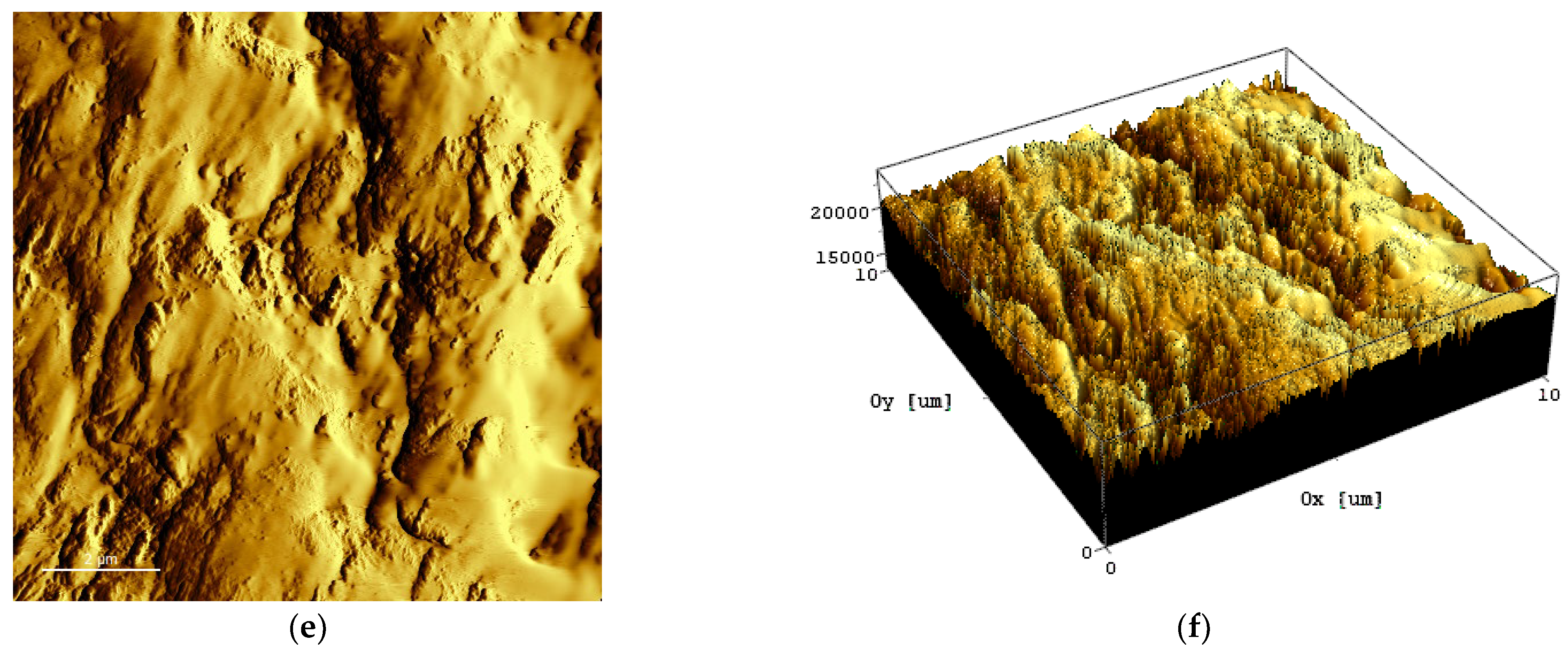
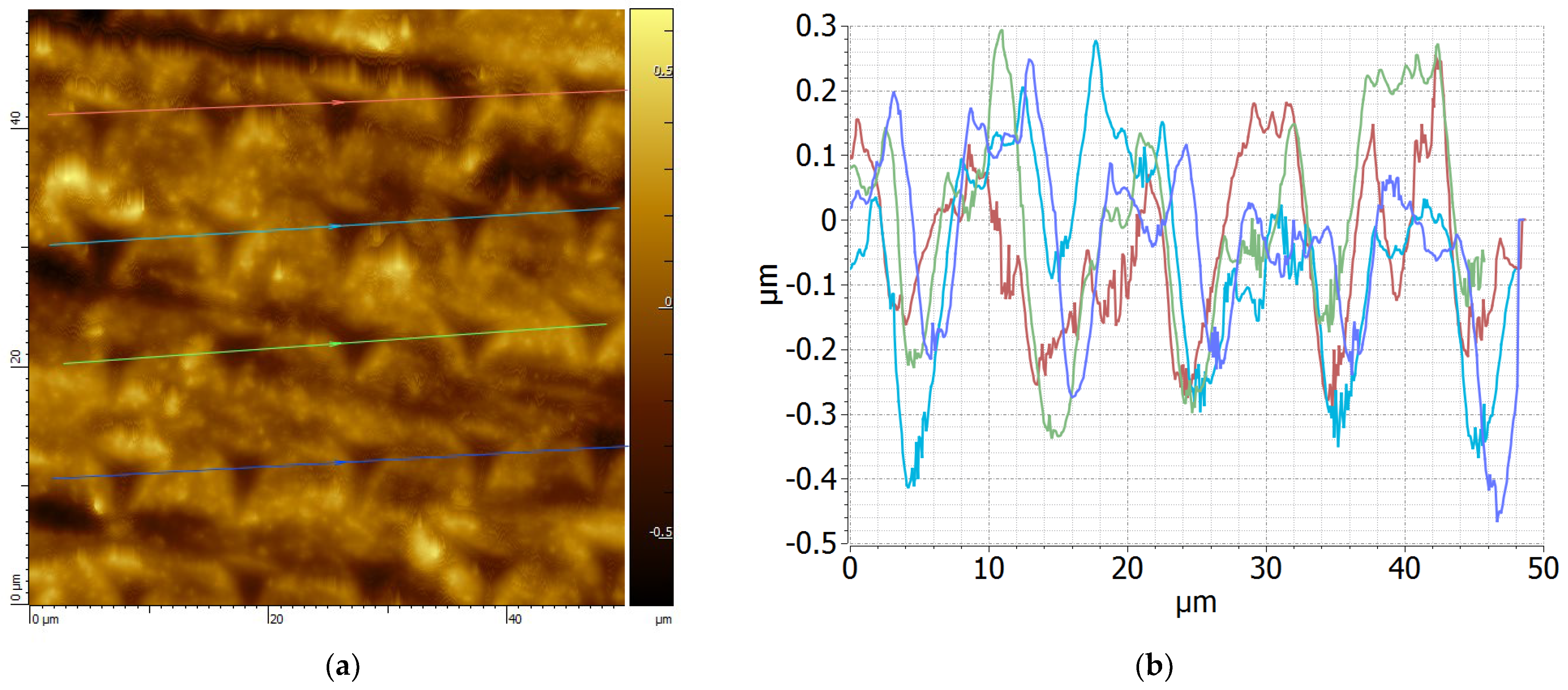
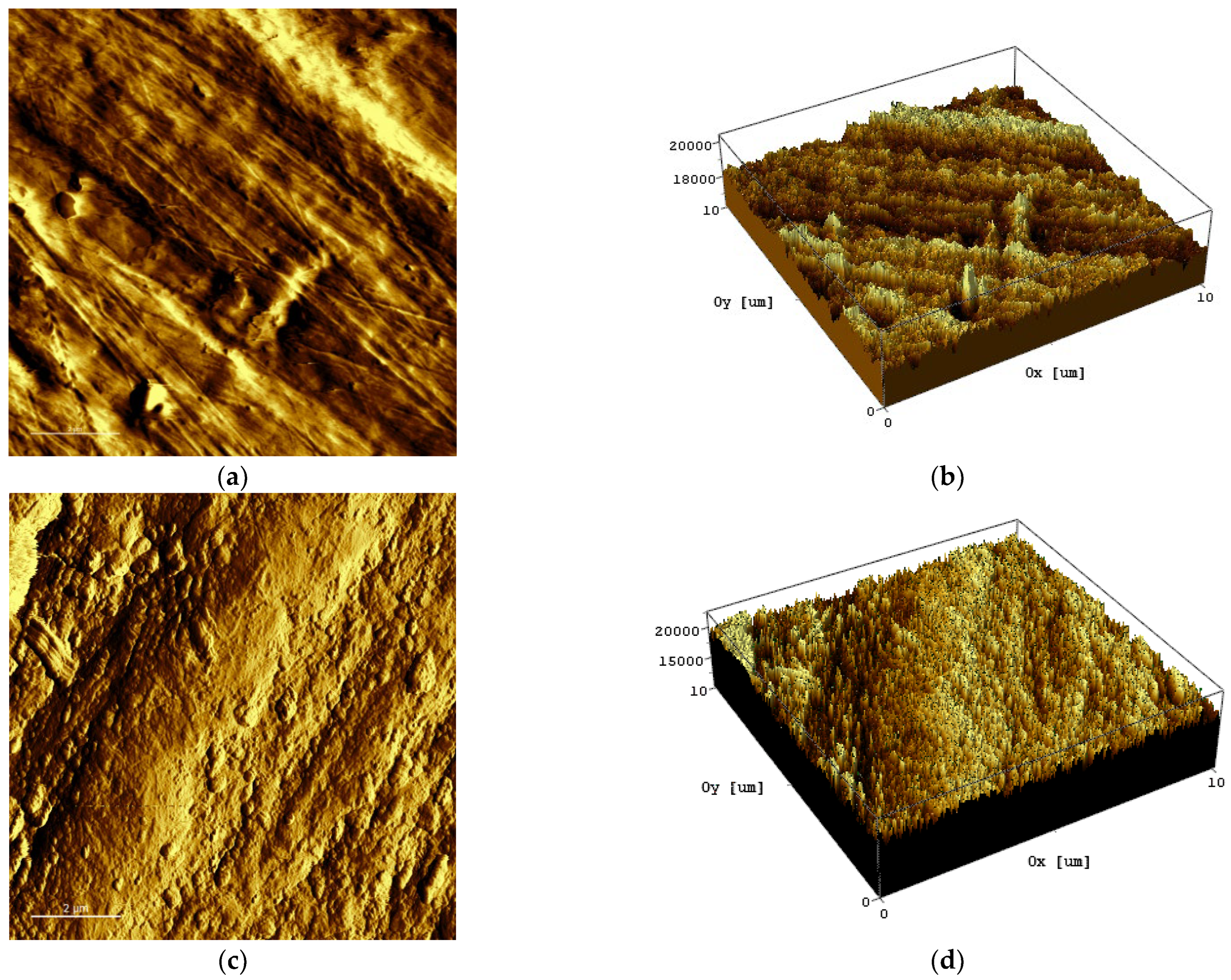
Polyetheretherketone (PEEK) plates, with an area of 10 mm2 and 5 mm thickness, manufactured by Ensinger (based on Victrex® PEEK 450 G or Solvay‘s KetaSpire® KT-820 polymer) were investigated. The polymer plates underwent irradiation by fast electrons at room temperature using the ILU-10 industrial electron pulse accelerator facility at the Park of Nuclear Technologies in Kurchatov, Kazakhstan [30]. An alternating high-frequency (HF) electric field was used to accelerate electrons. The radiation source was a copper toroidal resonator equipped with a triode electron gun operating at 50 MHz frequency. The accelerator’s electron beam energy and beam current were set at 2.7 MeV and 6.87 mA, respectively. The electron beam diameter on the sample surface and pulse duration were set to 10 mm and 0.4−0.5 ms, respectively. The polymer plates were exposed to a total dose of 400 kGy.

2.2. SPM

The surface morphology of the PEEK samples was measured using the Smart SPM1000 SPM. AppNano silicon probes, ACST series, designed for soft tapping/non-contact mode measurements were used. A cantilever with the size of 150 μm × 28 μm × 3 µm and stiffness 7.8 N/m was oscillated at the frequency of 150 kHz. The tetrahedrally shaped, Au coated, 14–16 μm long cantilever tip was made of n-type antimony doped single crystalline Si with resistivity 0.01–0.025 ohm/cm and 6 nm radius of curvature.

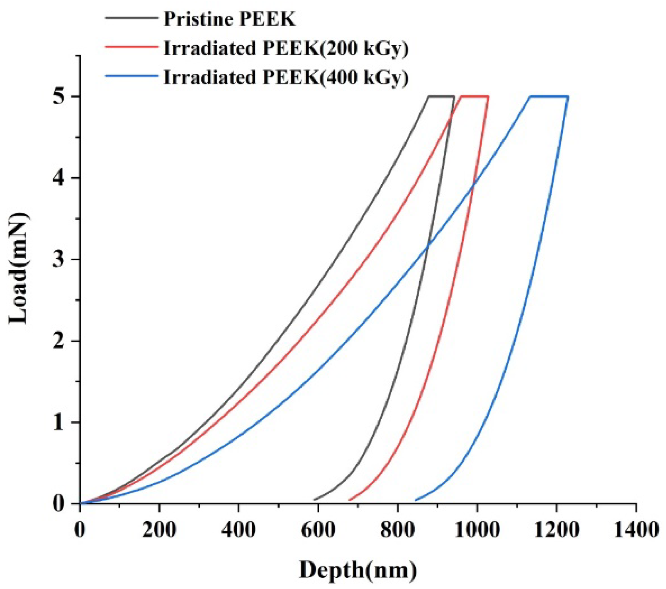
2.3. Nanoindentation

All PEEK samples were nanoindented using the Bruker Hysitron TI Premier nano-scale imaging and surface analysis system. Young’s modulus and hardness were measured using the Oliver and Farr method [31]. The penetrating body was a Berkovich indenter (Ѳ = 65.27°) with the maximum load of 10 mN, and holding time of 5 s. Nanoindentation was tested from 100 points and results were averaged for each sample.
Indentation hardness H was determined using the following equation:
H = P m a x A c ,
where Pmax is the maximum applied load; Ac is the contact area defined by
A c = 24.5   h c 2
where h c is the indentation contact depth as follows:
h c = h m a x ε P m a x S ,
with hmax and S = dP/dh being the maximum contact indentation depth and contact stiffness or unloading slope, respectively. The ε is a constant depending on the indenter shape (ɛ = 0.75 [31]). Pmax, hmax, and S were all obtained from measurements.
Young’s elastic modulus was given by the following formula:
E = d P d h   1 2 π A c ,
where P is the applied load and h is the indentation contact depth [31].

2.4. Brillouin Spectroscopy and FTIR

Brillouin spectra of the initial and irradiated polymer plates were recorded in the 180° backscattering geometry using a (3+3)-pass tandem JRS Fabry-Perot interferometer [32] (Table Stable Inc., Mettmenstetten, Switzerland). The free spectral range was set at 25 GHz. The incident 532 nm wavelength laser light was focused down to 2 µm spot diameter using 20× microscope objective, while the optical power of the laser beam was kept below 10 mW to prevent sample damage. During optical (non-contact) Brillouin measurements, the sample temperature was controlled using a Peltier PE120 temperature-controlled stage (Linkam Instruments, Inc., Redhill, UK) over a 20–120 °C temperature range. Brillouin spectra were measured from 5 different points for each temperature value and for each sample.
FTIR spectra of the samples were measured using a Thermo Scientific (Waltham, MA, USA) Nicolet iS10 spectrometer. The spectrometer was equipped with automatic spectral identification tools.

3. Results

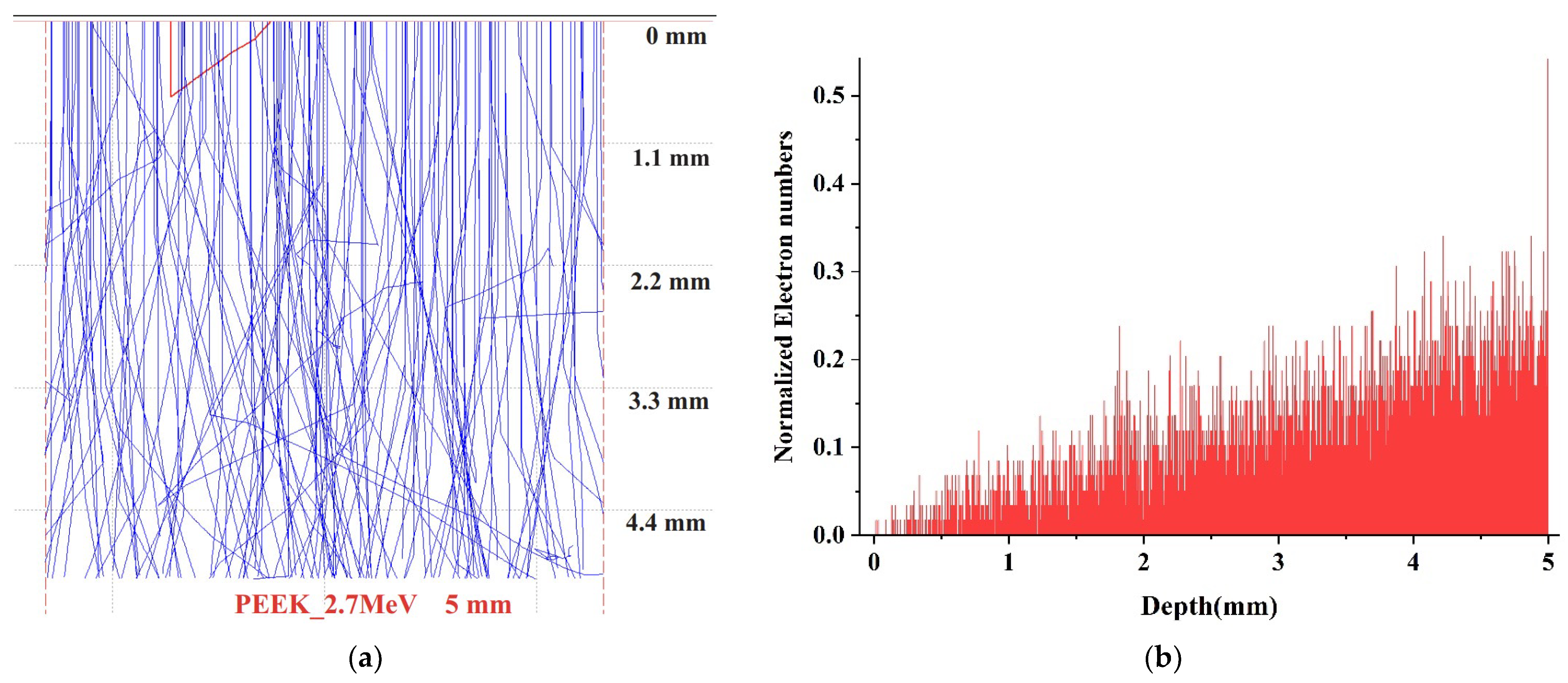
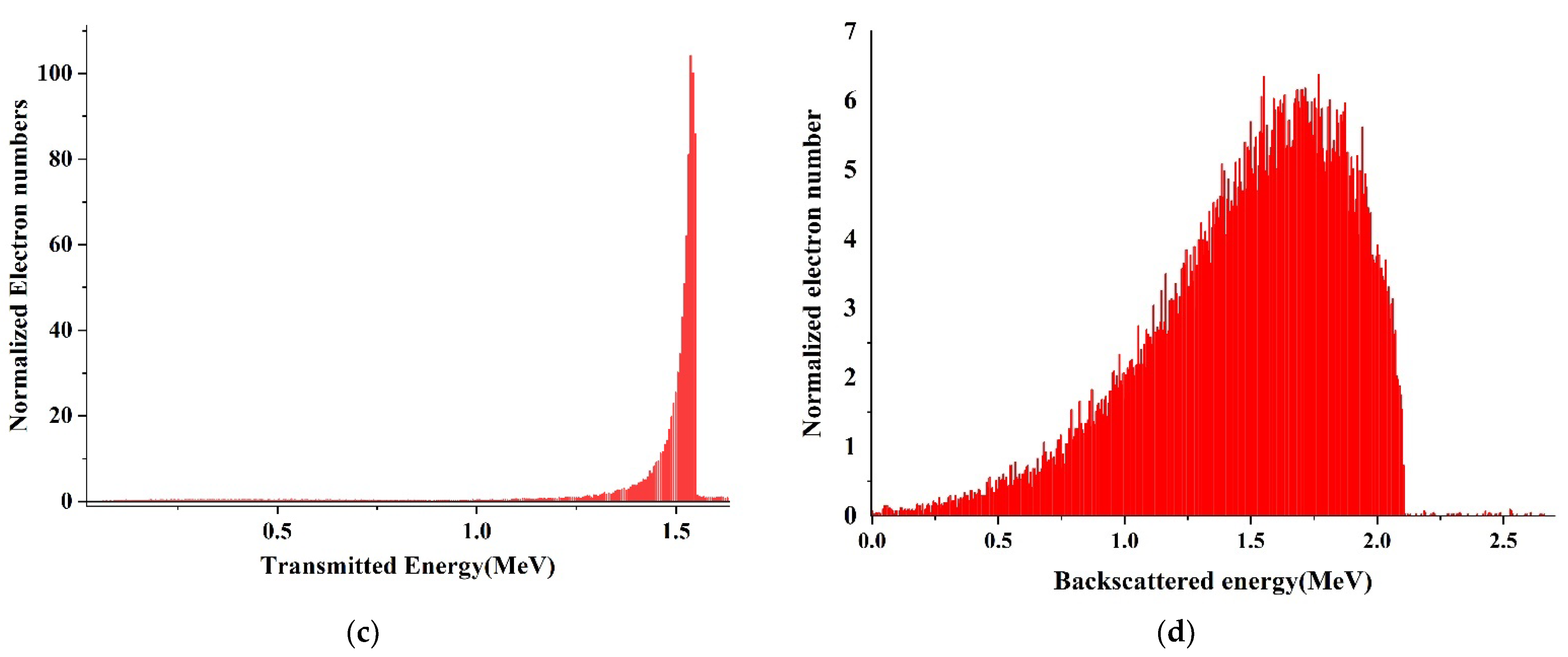
3.1. Assessment of Electron Penetration Depth

In this study, monte CArlo SImulation of electroN trajectory in sOlids (CASINO) software was used to estimate the penetration depth of electrons, backscattered and transmitted energy in PEEK samples. The complete electron trajectories in the material was estimated using Monte-Carlo simulation, as described in detail by Drouin et al. [33,34]. PEEK was modeled using the chemical composition density of 1.3 g cm 3 and thickness of 5 mm, as given by the supplier. The number of electrons was 100,000 and the specified electron beam diameter was 10 mm, where the irradiation covered the whole sample surface. Figure 1 represents the simulation results of PEEK irradiated with 2.7 MeV electron energy. It can be clearly seen that the electrons with the energy of 2.7 MeV completely pass through the sample (Figure 1a). When the energy of the primary beam increases, the penetration depth is also enhanced [35]. The depth profiling of electron distributions in the sample is shown in Figure 1b. The number of electrons inside the sample is much lower than the initial electron number, and this indicates that the 2.7 MeV electron beam with such strong energy can completely penetrate the entire PEEK structure, and that less electron detainment occurred in the sample. It is also seen in Figure 1c, where most of the electrons are transmitted rather than absorbed in the 2.7 MeV irradiated sample, and their energies are ~1.5 MeV. The electrons continuously change their direction of travel across the polymer due to their elastic backscattering with the host atomic nuclei [36]. The backscattered electrons reach a maximum energy of 2.1 MeV during incident, and 2.7 MeV electron beams, respectively, as displayed in Figure 1d. Moreover, the estimation of electron penetration depth gives valuable information to make sure that we have provided all measurements exactly where the electrons passed and made structural changes. Simultaneous cross-linking and chains scission of PEEK macromolecules under high-dose electron beam irradiation was observed in Ref. [37].
The 2D and 3D morphology images of pristine (a, b) and irradiated (c–f) PEEK are shown in Figure 2.
The roughness analysis of pristine and irradiated PEEK was performed for a scan area of 101.841 µm2 and 101.642 µm2, respectively. The sample surface before irradiation (Figure 2a) exhibited irregular grooves and bumps. Apparently, these grooves were formed as a result of polishing the sample. The average surface roughness (Ra) of pristine PEEK was relatively high at 265 nm (See Table 1). The irradiation of PEEK with a dose of 200 Gr led to a significant increase in the number of bumps. Wherein, the bumps’ length decreased, their depth increased. The average surface roughness (Ra) of the irradiated PEEK increased significantly and amounted to 750 nm. We believe that the increase in the surface roughness of the sample was caused by radiation damage during irradiation. With an increase in the irradiation dose to 400 kGy, the surface of the sample was smoothed, and the average surface roughness decreased to 665 nm. Most likely, this was due to evaporation and partial melting of the sample surface.

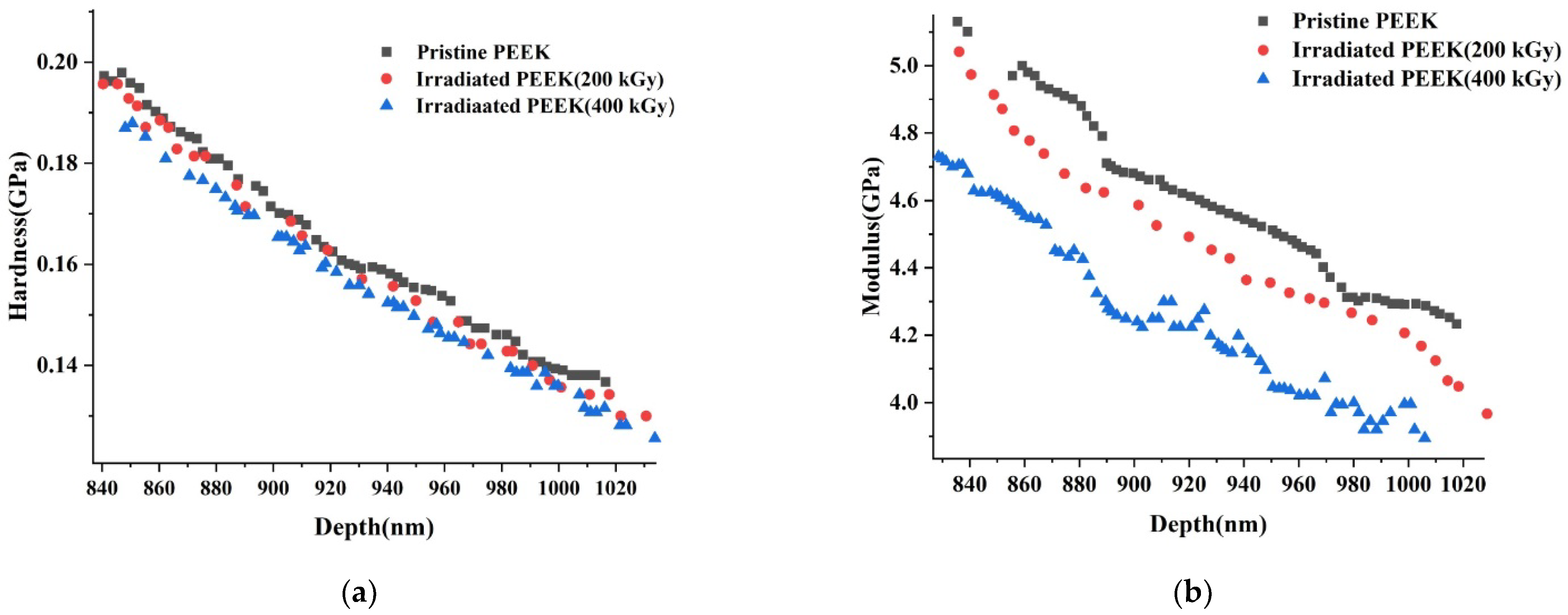
3.2. Nanoindentation

Typical loading and unloading curves for pristine and irradiated PEEK surfaces are shown in Figure 3. The loading-unloading speed was set at 200 mN/s with the penetration depth reaching a maximum of 1100 nm. For each sample, 100 indents were implemented. The indents were located at a distance of about 5–10 µm from each other. The trapezoidal load function was such that loading, holding and unloading segments lasted for 5, 10 and 5 s, respectively. In order to minimize the influence of the sample surface roughness on the indentation result, the smoothest areas were selected. The atomic force microscopy (AFM) images of the sample surface subjected to indentation are shown in Figure 4.
The indentation hardness and elastic modulus data as a function of indentation depth for the pristine and irradiated PEEK samples are shown in Figure 5a,b respectively.
The results of measuring the hardness and elastic modulus of PEEK samples before and after electron irradiation by the nanoindentation method are presented in Table 2.
The proportionality constant between H and E values for pristine PEEK was 0.039, and results for PEEK samples irradiated at 200 kGy and 400 kGy were the same, being 0.038. Our results are consistent with the literature data as shown in Table 3. Besides, H/E values measured for a range of materials using nanoindentation vary from 0.0067 to 0.1, and our H/E results are in this range [38].
A close relationship between such properties of polymers as the elastic modulus (E), shear modulus (G), yield strength (Y) and hardness (H) was shown in the work [39]. Tabor [40] found that H is proportional to the macroscopic yield stress as follows:
H 3 Y
Another approximate formula for amorphous polymers was derived by Struik [41]:
E 30 Y
Combining Equations (5) and (6) we can derive a very simplified formula as follows:
H 3 Y E / 10
Although the values of the constants in Equation (7) are approximate, the linear relationships between H, Y, E and G usually hold very well. In particular, linear H-Y-E-G ratios were observed for amorphous and semicrystalline polymers [39,42] and for cross-linked polymers [43,44]. Moreover, linear proportionality between properties has also been observed for multiphase, multicomponent polymer systems [45,46].

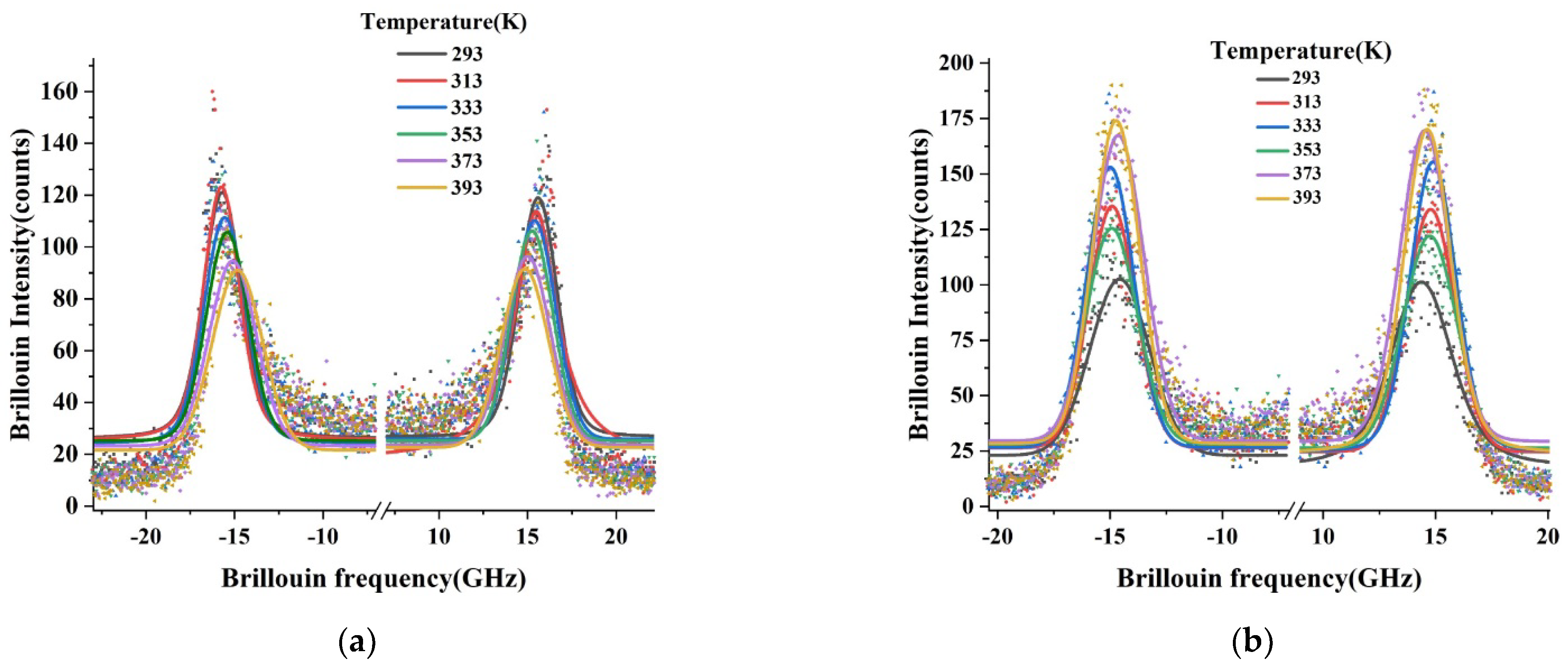
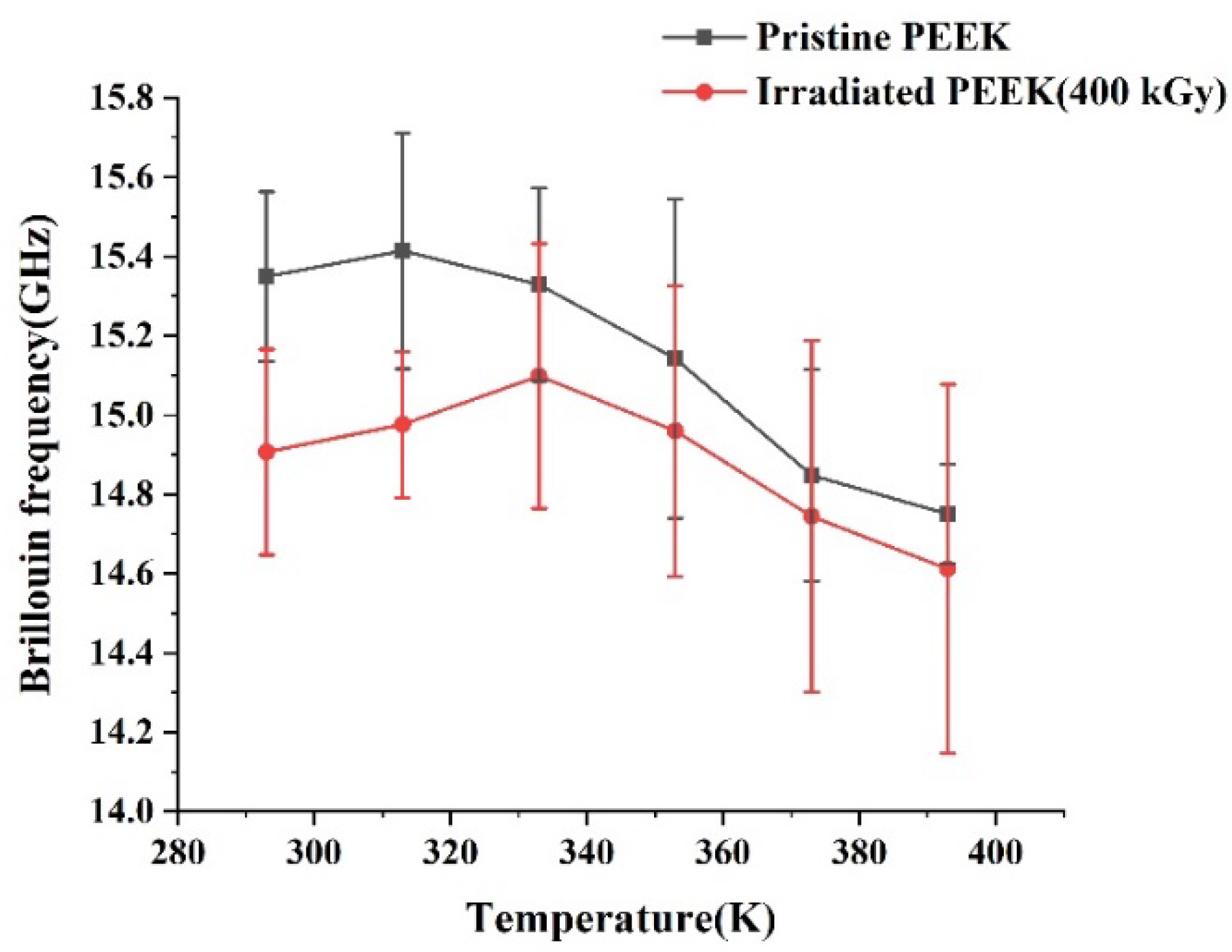
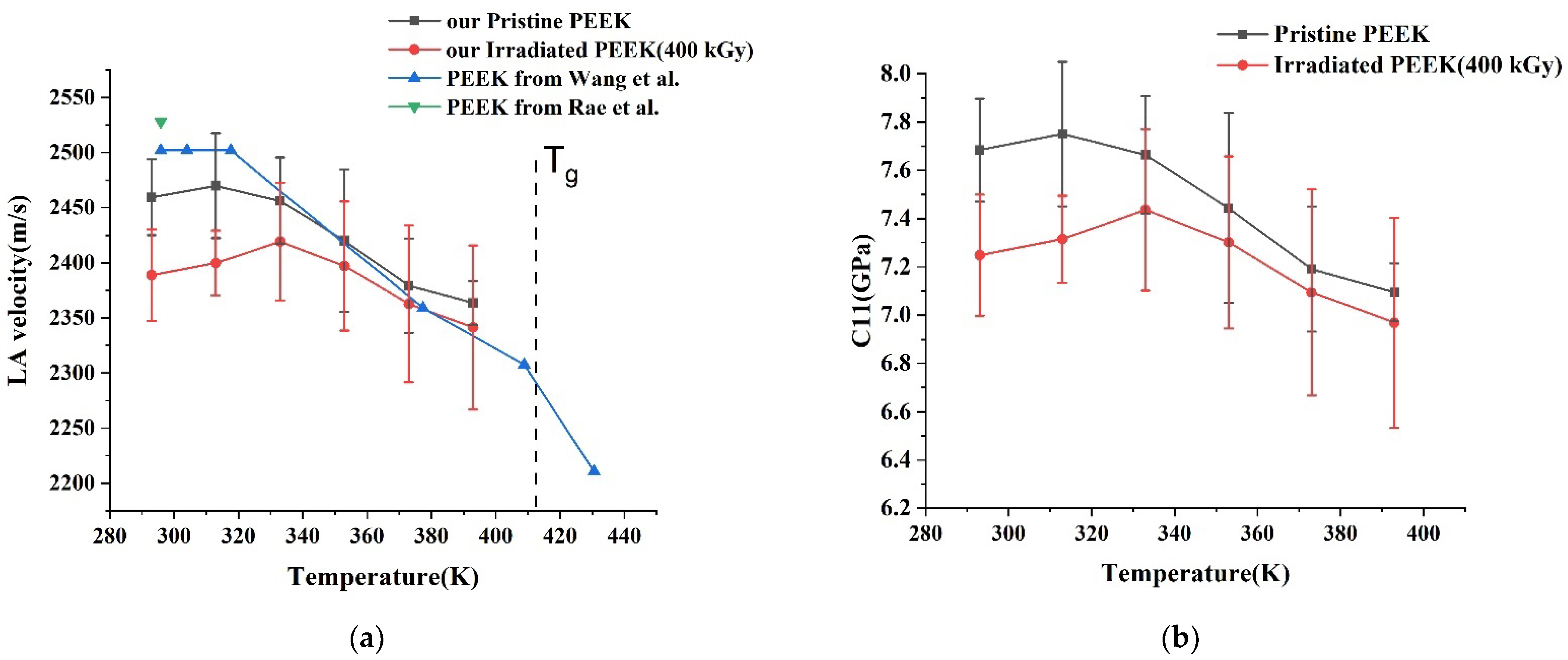
3.3. Brillouin Specrtoscopy
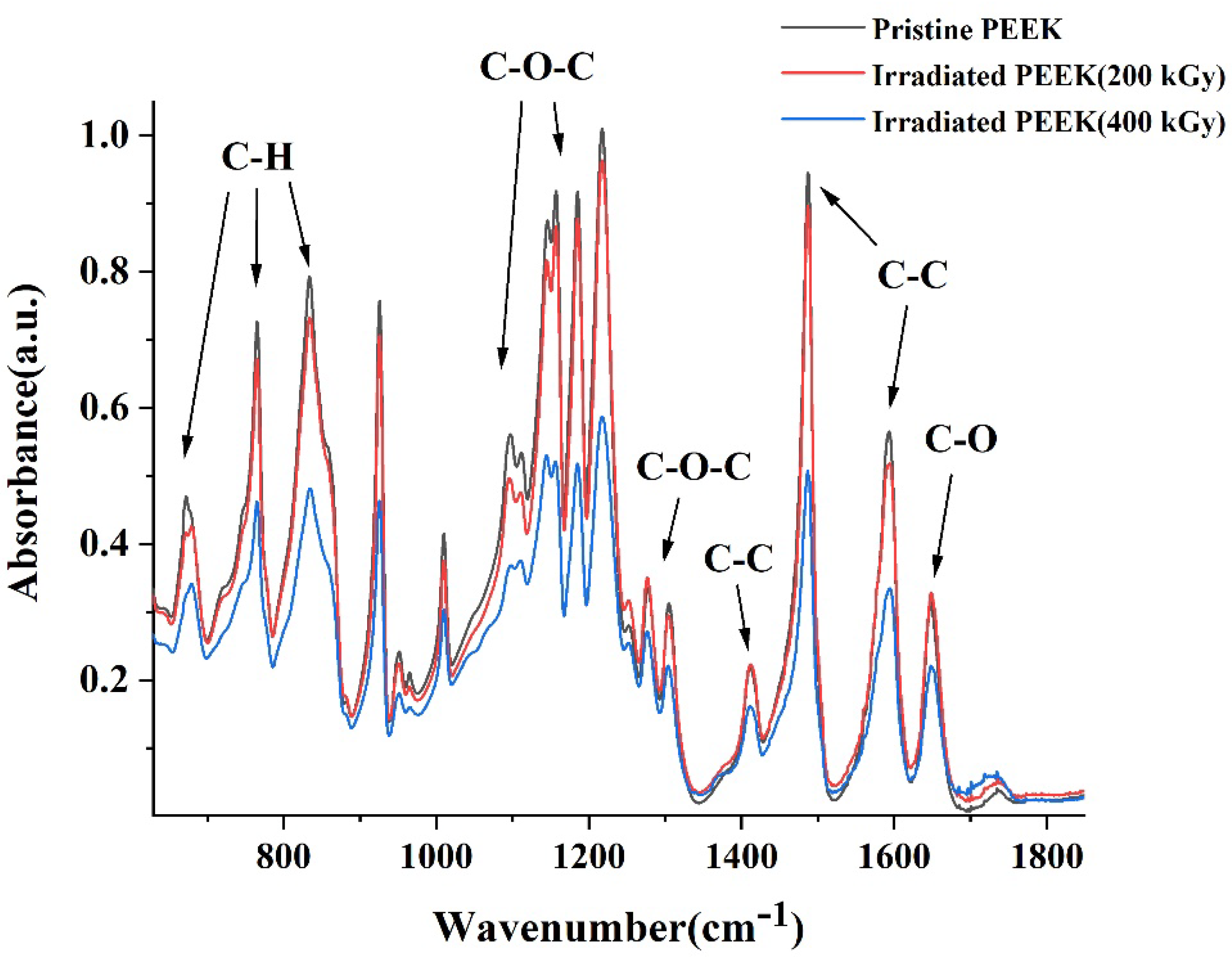
Stokes and anti-Stokes sides of the Brillouin spectra of pristine and irradiated PEEK samples under different temperatures are shown in Figure 6. The signal acquisition time was 10 min for each spectrum. All reported positions of measured Brillouin peaks are the results of the Voigt fitting.
Figure 7 shows the frequency shift of longitudinal acoustic (LA) phonons from pristine and irradiated PEEK samples measured at different temperatures.
The connection between the frequency shift of ϑ of Brillouin peaks and the phase velocity V of the corresponding acoustic mode directly derived as follows [47,48]:
V L = λ i ϑ L 2 n ,
where ϑL is the longitudinal acoustic phonon frequency deduced from the Brillouin peak frequency shift; λi is the incident light wavelength and n is the refractive index of the material.
Using measured LA phonon velocity one can estimate longitudinal elastic modulus C11 [48,49,50] as follows:
C 11 = ρ V L 2 ,
where ρ is the density of the material. We observe the softening of LA phonon velocity resulting in the subsequent decrease of C 11 with the rise of temperature, assuming that the PEEK’s mass density was not altered.
As the backscattering geometry only allows the frequency of LA phonons to register, the frequency of transverse acoustic (TA) phonons was taken from the literature [48] to assess TA phonon velocity using modified Formula 8, according to the scattering geometry. Consequently, assuming that PEEK is elastically isotropic, the shear elastic modulus C 44 can be determined as follows:
C 44 = ρ V b 2 , V b 2 = V L 2 4 3 V T 2
where V b —bulk sound velocity.
Furthermore, the knowledge of compressional and shear modules allows us to find Young’s modulus as follows:
E = C 44 ( 3 C 11 4 C 44 ) C 11 C 44
Figure 8 shows the variation of LA phonon velocity (a) and C11 elastic module (b) with temperature. Finally, in Table 4 we list comparative results of Young’s moduli determined by nanoindentation and Brillouin spectroscopy for pristine PEEK, but it was not possible to compare Young’s moduli for irradiated PEEK due to the lack of transversal phonon values available from the literature. However, as can be seen from Table 4, Young’s moduli values found using both techniques are quite near to each other for pristine PEEK. It proves that LA sound velocity and C 11 elastic constant values are correct for the irradiated sample.

3.4. FTIR

The FTIR spectra of pristine and irradiated PEEK samples are shown in Figure 9. The band at 1650 cm−1 has been assigned to the carbonyl stretching vibration, a number of skeletal ring vibrations at 1598, 1490 and 1413 cm−1, the asymmetric stretching of ether group at 1277 and 1190 cm−1, the aromatic hydrogen in-plane deformation at 1155, 1215 and 1105 cm−1, and the aromatic hydrogen’s out of plane bending modes occurred at 765, 860–841 cm−1 (broad band) and diphenyl ketone band at 927 cm−1. As the electron beam radiation dose increases, the rate of chain scission increases, which is supported by the fact that the absorption intensity of each group decreased slightly with the increase of the irradiation dose. In addition, the dipole moment of the PEEK polymer changed due to irradiation, whereas infrared scattering of the material surface improved, leading to the weakening of the absorption intensity. Moreover, oxidation related peak at 1730 cm−1 enhances as a function of irradiation. On average it can be concluded that an increase in dose by two times leads to further scission and oxidation, which can be seen from the typical radiation-induced mechanical change in PEEK [28,51].

4. Discussion

Apparently, the increase in our PEEK surface roughness after irradiation with 2.7 MeV at a dose of 200 kGy is due to electron beam-induced sputtering. A similar effect of polyamide sputtering after irradiation with a 6 MeV pulsed electron beam was observed earlier [52]. In particular, the authors of this work found that the average roughness index (Ra) of the irradiated sample, measured by surface profilometry, increased from 0.06 to 0.1.
The degradation of the mechanical properties of irradiated PEEK can be explained in terms of structural transformations induced by irradiation. The chemical structure of pristine PEEK is illustrated in Figure 10.
The mechanical strength, high thermal and radiation resistance of the polymer is due to the aromatic ring in its composition. Flexibility is provided by the ether bond of oxygen in the main chain. The decrease in density and increase in free volume, leading to greater intermolecular interaction, is provided by the side ketone group. The binding energies of PEEK molecular components highlighted in the literature are shown in Table 5.
In general, the irradiation of polymers including PEEK with high-energy electrons is accompanied by chain scission or crosslinking, as well as changes in their crystallinity and microstructure [34,55]. Obviously, an electron accelerated to an energy of 2.7 MeV can easily break the bonds of any macromolecules in PEEK, since the electron beam energy is much higher than the binding energy of any of the major organic component groups listed in Table 3. We believe that chain (bonds) scission processes were dominant in our experiments on sample irradiation.
We also note that the elastic property measurement results of pristine PEEK obtained from nanoindentation and Brillouin spectroscopy support each other. Further softening of the PEEK structure is deduced to be from the rise of temperature, and irradiation dose.

5. Conclusions

The morphology, mechanical and chemical properties of 5 mm thick PEEK plates before and after irradiation with 2.7 MeV electrons with the doses of 200 kGy and 400 kGy were characterized. The CASINO calculation results showed that electrons with an energy of 2.7 MeV penetrated the entire sample. SPM results showed that the surface roughness of PEEK increased when irradiated at a dose of 200 kGy. However, a further increase in the irradiation dose to 400 kGy led to a decrease in the roughness. The nanoindentation and Brillouin results demonstrated with high accuracy, the decay of the hardness and elastic moduli of PEEK with the increase of irradiation dose. PEEK shows more radiation resistance at its surface than in its bulk. Moreover, the elastic properties of both irradiated and pristine PEEK deteriorate with rising temperature.

Author Contributions

Conceptualization, Z.U., N.A. and Z.I.; methodology, N.A.; software, B.K. and Z.I.; validation, N.Z., B.R. and Z.S.; formal analysis, N.S. and Z.A.; investigation, B.K. and N.A.; resources, G.A.; data curation, B.K.; writing—original draft preparation, N.A. and B.K.; writing—review and editing, Z.U. and Z.I.; visualization, B.K.; supervision, N.A.; project administration, Z.I. and Z.U.; funding acquisition, Z.U., N.A. and B.K. have equally contributed to the co-first authorship. All authors have read and agreed to the published version of the manuscript.

Funding

This research was funded by Nazarbayev University CRP grant number 11022021CRP1504.

Data Availability Statement

The research data are available upon a written request.

Acknowledgments

N.A. acknowledges the postdoctoral Scholarship Programme from the Ministry of Education and Science of the Republic of Kazakhstan (Grant No. AP13268877) “Development of manufacturing technology for radiation-resistant electronic components of artificial Earth satellites”. N.Z. acknowledges the Scholarship Programme from the Islamic Development Bank (ID2021-588606). B.K. and Z.U. acknowledge funding by Nazarbayev University CRP grant number 11022021CRP1504.

Conflicts of Interest

The authors declare no conflict of interest. The funders had no role in the design of the study; in the collection, analyses, or interpretation of data; in the writing of the manuscript, or in the decision to publish the results.

References

  1. May, R. Polyetheretherketones. In Encyclopedia of Polymer Science and Technology; John Wiley & Sons Inc.: Hoboken, NJ, USA, 2002. [Google Scholar]
  2. Hegazy, E.S.A.; Sasuga, T.; Nishii, M.; Seguchi, T. Irradiation effects on aromatic polymers: 2. Gas evolution during electron-beam irradiation. Polymer 1992, 33, 2904–2910. [Google Scholar] [CrossRef]
  3. Kurtz, S.M. Chapter 6—Chemical and Radiation Stability of PEEK. In Plastics Design Library, PEEK Biomaterials Handbook; Kurtz, S.M., Ed.; William Andrew Publishing: Norwich, NY, USA, 2012; pp. 75–79. ISBN 9781437744637. [Google Scholar]
  4. Harding, M.J.; Brady, S.; O’Connor, H.; Lopez-Rodriguez, R.; Edwards, M.D.; Tracy, S.; Dowling, D.; Gibson, G.; Girard, K.P.; Ferguson, S. 3D printing of PEEK reactors for flow chemistry and continuous chemical processing. React. Chem. Eng. 2020, 5, 728–735. [Google Scholar] [CrossRef]
  5. Searle, O.B.; Pfeiffer, R.H. Victrex® poly (ethersulfone)(PES) and Victrex® poly (etheretherketone)(PEEK). Polym. Eng. Sci. 1985, 25, 474–476. [Google Scholar] [CrossRef]
  6. Shekar, R.I.; Kotresh, T.M.; Rao, P.D.; Kumar, K. Properties of high modulus PEEK yarns for aerospace applications. J. Appl. Polym. Sci. 2009, 112, 2497–2510. [Google Scholar] [CrossRef]
  7. Chinthavali, M. 3D printing technology for automotive applications. In Proceedings of the 2016 International Symposium on 3D Power Electronics Integration and Manufacturing (3D-PEIM), Raleigh, NC, USA, 13–15 June 2016; pp. 1–13. [Google Scholar]
  8. Page, J.Y.S.D.; Bonon, H.W.; Bui, V.T. Neutron and gamma radiation effects on the viscoelastic behavior of poly (aryl ether ether ketone). In Proceedings of the Powering Canada’s Future, Toronto, ON, Canada, 8–11 June 1997. [Google Scholar]
  9. Bonin, H.W.; Vui, V.T.; Legault, J.F. High polymer composites for containers for the long-term storage of spent nuclear fuel and high level radioactive waste. In Proceedings of the Powering Canada’s Future, Toronto, ON, Canada, 8–11 June 1997. [Google Scholar]
  10. Kumar, R.; Singh, R. Thermoplastic Containers for Disposal of Radioactive Waste. In Reference Module in Materials Science and Materials Engineering; Elsevier: Amsterdam, The Netherlands, 2020. [Google Scholar]
  11. Siewert, B.; Plaza-Castro, M.; Sereno, N.; Jarman-Smith, M. Applications of PEEK in the dental field. In PEEK Biomaterials Handbook; William Andrew Publishing: Norwich, NY, USA, 2019; pp. 333–342. [Google Scholar]
  12. Kurtz, S.M.; Lanman, T. Dynamic stabilization and semirigid PEEK rods for spinal fusion. In PEEK Biomaterials Handbook; William Andrew Publishing: Norwich, NY, USA, 2019; pp. 281–289. [Google Scholar]
  13. Huang, T.; Song, J.; He, H.; Zhang, Y.B.; Li, X.M.; He, T. Impact of SPEEK on PEEK membranes: Demixing, morphology and performance enhancement in lithium membrane extraction. J. Membr. Sci. 2020, 615, 118448. [Google Scholar] [CrossRef]
  14. Li, D.; Shi, D.; Feng, K.; Li, X.; Zhang, H. Poly (ether ether ketone) (PEEK) porous membranes with super high thermal stability and high rate capability for lithium-ion batteries. J. Membr. Sci. 2017, 530, 125–131. [Google Scholar] [CrossRef]
  15. Tahir, Z.; Ilyas, A.; Li, X.; Bilad, M.R.; Vankelecom, I.F.; Khan, A.L. Tuning the gas separation performance of fluorinated and sulfonated PEEK membranes by incorporation of zeolite 4A. J. Appl. Polym. Sci. 2018, 135, 45952. [Google Scholar] [CrossRef]
  16. da Silva Burgal, J.; Peeva, L.; Livingston, A. Towards improved membrane production: Using low-toxicity solvents for the preparation of PEEK nanofiltration membranes. Green Chem. 2016, 18, 2374–2384. [Google Scholar] [CrossRef] [Green Version]
  17. Manas, D.; Manas, M.; Mizera, A.; Navratil, J.; Ovsik, M.; Tomanova, K.; Sehnalek, S. Use of irradiated polymers after their lifetime period. Polymers 2018, 10, 641. [Google Scholar] [CrossRef] [Green Version]
  18. Tavlet, M.; Van der Burgt, H. Radiation Resistance and Other Safety Aspects of High-Performance Plastics by ERTA; No. CERN-TIS-94-13; CERN: Meyrin, Switzerland, 1994. [Google Scholar]
  19. Sasuga, T.; Kudoh, H. Ion irradiation effects on thermal and mechanical properties of poly (ether–ether–ketone)(PEEK). Polymer 2000, 41, 185–194. [Google Scholar] [CrossRef]
  20. Rao, G.R.; Lee, E.H. Effects of sequential He+ and Ar+ implantation on surface properties of polymers. J. Mater. Res. 1996, 11, 2661–2667. [Google Scholar] [CrossRef]
  21. Nakamura, H.; Nakamura, T.; Noguchi, T.; Imagawa, K. Photodegradation of PEEK sheets under tensile stress. Polym. Degrad. Stab. 2006, 91, 740–746. [Google Scholar] [CrossRef] [Green Version]
  22. Kornacka, E.M.; Przybytniak, G.; Nowicki, A. Radical processes initiated by ionizing radiation in PEEK and their macroscopic consequences. Polym. Adv. Technol. 2019, 30, 79–85. [Google Scholar] [CrossRef] [Green Version]
  23. Woo, L.; Sandford, C.L. Comparison of electron beam irradiation with gamma processing for medical packaging materials. Radiat. Phys. Chem. 2002, 63, 845–850. [Google Scholar] [CrossRef]
  24. El-Saftawy, A.A.; Elfalaky, A.; Ragheb, M.S.; Zakhary, S.G. Electron beam induced surface modifications of PET film. Radiat. Phys. Chem. 2014, 102, 96–102. [Google Scholar] [CrossRef]
  25. Rahman, M.S.; Shaislamov, U.; Yang, J.; Kim, J.; Yu, Y.H.; Choi, S.; Lee, H. Effects of electron beam irradiation on tribological and physico-chemical properties of Polyoxymethylene copolymer (POM-C). Nucl. Instrum. Methods Phys. Res. B 2016, 387, 54–62. [Google Scholar] [CrossRef]
  26. Ovsik, M.; Manas, M.; Stanek, M.; Dockal, A.; Mizera, A.; Fluxa, P.; Bednarik, M. Adamek, M. Nano-Mechanical Properties of Surface Layers of Polyethylene Modified by Irradiation. Materials 2020, 13, 929. [Google Scholar] [CrossRef] [Green Version]
  27. Li, H.; Yang, J.; Lv, G.; Dong, S.; Tian, F.; Dong, S.; Li, X. In-Situ saxs/waxd analysis on structural evolution in peek irradiated by 1 MeV electrons during tensile deformation. Polym. Degrad. Stab. 2020, 181, 109350. [Google Scholar] [CrossRef]
  28. Rival, G.; Dantras, E.; Paulmier, T. Electronic irradiation ageing in the vicinity of glass transition temperature for PEEK space applications. Polym. Degrad. Stab. 2020, 181, 109305. [Google Scholar] [CrossRef]
  29. Steelman, Z.A.; Weems, A.C.; Traverso, A.J.; Szafron, J.M.; Maitland, D.J.; Yakovlev, V.V. Revealing the glass transition in shape memory polymers using Brillouin spectroscopy. Appl. Phys. Lett. 2017, 111, 241904. [Google Scholar] [CrossRef]
  30. Auslender, V.L. ILU-type electron accelerators for industrial technologies. Nucl. Instrum. Methods Phys. Res. Sect. B Beam Interact. Mater. At. 1994, 89, 46–48. [Google Scholar] [CrossRef]
  31. Oliver, W.C.; Pharr, G.M. Measurement of hardness and elastic modulus by instrumented indentation: Advances in understanding and refinements to methodology. J. Mater. Res. 2004, 19, 3–20. [Google Scholar] [CrossRef]
  32. Coker, Z.; Troyanova-Wood, M.; Traverso, A.J.; Yakupov, T.; Utegulov, Z.N.; Yakovlev, V.V. Assessing performance of modern Brillouin spectrometers. Opt. Express 2018, 26, 2400–2409. [Google Scholar] [CrossRef]
  33. Drouin, D.; Couture, A.R.; Joly, D.; Tastet, X.; Aimez, V.; Gauvin, R. CASINO V2.42—A Fast and Easy-to-use Modeling Tool for Scanning Electron Microscopy and Microanalysis Users. Scanning 2007, 29, 92–101. [Google Scholar] [CrossRef]
  34. Rival, G.; Paulmier, T.; Dantras, E. Influence of electronic irradiations on the chemical and structural properties of PEEK for space applications. Polym. Degrad. Stab. 2019, 168, 108943. [Google Scholar] [CrossRef]
  35. Tiwari, P.; Srivastava, A.K.; Khattak, B.Q.; Verma, S.; Upadhyay, A.; Sinha, A.K.; Ganguli, T.; Lodha, G.S.; Deb, S.K. Structural modification of poly (methyl methacrylate) due to electron irradiation. Measurement 2014, 51, 1–8. [Google Scholar] [CrossRef]
  36. Assa’d, A.M.D. Monte Carlo calculation of the backscattering coefficient of thin films of low on high atomic number materials and the reverse as a function of the incident electron energy and film thickness. Appl. Phys. A 2018, 124, 1–6. [Google Scholar] [CrossRef]
  37. Sasuga, T.; Hagiwara, M. Radiation deterioration of several aromatic polymers under oxidative conditions. Polymer 1987, 28, 1915–1921. [Google Scholar] [CrossRef]
  38. Bolshakov, A.P.G.M.; Pharr, G.M. Influences of pileup on the measurement of mechanical properties by load and depth sensing indentation techniques. J. Mater. Res. 1998, 13, 1049–1058. [Google Scholar] [CrossRef]
  39. Balta-Calleja, F.J.; Fakirov, S. Microhardness of Glassy Polymers. In Microhardness of Polymers; Balta-Calleja, F.J., Fakirov, S., Eds.; Cambridge University Press: Cambridge, UK, 2000; pp. 46–79. [Google Scholar]
  40. Tabor, D. The Hardness of Metals; Oxford University Press: New York, NY, USA, 1951. [Google Scholar]
  41. Struik, L.C.E. Some problems in the non-linear viscoelasticity of amorphous glassy polymers. J. Non-Cryst. Solids 1991, 131–133, 395–407. [Google Scholar] [CrossRef]
  42. Balta-Calleja, F.J.; Fakirov, S. Microharndess of Crystalline Polymers. In Microhardness of Polymers; Balta-Calleja, F.J., Fakirov, S., Eds.; Cambridge University Press: Cambridge, UK, 2000; pp. 80–126. [Google Scholar]
  43. Slouf, M.; Pilar, J.; Dybal, J.; Sloufova, I.; Michalkova, D.; Lukesova, M.; Zgadzai, O.; Blank, A.; Filippov, S.K. UV degradation of styrene-butadiene rubber versus high density poly(ethylene) in marine conditions studied by infrared spectroscopy, micro indentation, and electron spin resonance imaging. Polym. Degrad. Stab. 2018, 156, 132–143. [Google Scholar] [CrossRef]
  44. Ramsdale-Capper, R.; Foreman, J.P. Internal antiplasticisation in highly crosslinked amine cured multifunctional epoxy resins. Polymer 2018, 146, 321–330. [Google Scholar] [CrossRef]
  45. Ostafinska, A.; Fortelny, I.; Nevoralova, M.; Hodan, J.; Kredatusova, J.; Slouf, M. Synergistic effects in mechanical properties of PLA/PCL blends with optimized composition, processing, and morphology. RSC Adv. 2015, 5, 98971–98982. [Google Scholar] [CrossRef]
  46. Balta-Calleja, F.J.; Cagiao, M.E.; Adhikari, R.; Michler, G.H. Relating microhardness to morphology in styrene/butadiene block copolymer/polystyrene blends. Polymer 2004, 45, 247–254. [Google Scholar] [CrossRef] [Green Version]
  47. Stevens, L.L.; Orler, E.B.; Dattelbaum, D.M.; Ahart, M.; Hemley, R.J. Brillouin-scattering determination of the acoustic properties and their pressure dependence for three polymeric elastomers. J. Chem. Phys. 2007, 127, 104906. [Google Scholar] [CrossRef]
  48. Wang, J.; Zhou, Q.; Chao, D.; Li, F.; Cui, T. In situ determination of mechanical properties for poly (ether ether ketone) film under extreme conditions. RSC Adv. 2017, 7, 8670–8676. [Google Scholar] [CrossRef] [Green Version]
  49. Utegulov, Z.N.; Wicksted, J.P.; Shen, G.Q. Role of Al Formers and Na Modifers in Al2O3-Sio2-Na2O-Mgo-Eu2O3 Glassess: Brillouin and Raman Spectroscopy Studies. Phys. Chem. Glasses 2004, 45, 166–172. [Google Scholar]
  50. Shen, G.Q.; Utegulov, Z.N.; Wicksted, P.J.; Mian, S.M. Effects of the rare earth modifier on the Brillouin scattering from soda magnesia alumina silicate glasses. Phys. Chem. Glasses 2002, 43, 73–79. [Google Scholar]
  51. Al Lafi, A.G. FTIR spectroscopic analysis of ion irradiated poly (ether ether ketone). Polym. Degrad. Stab. 2014, 105, 122–133. [Google Scholar] [CrossRef]
  52. Mathakari, N.L.; Bhoraskar, V.N.; Dhole, S.D. 6 MeV pulsed electron beam induced surface and structural changes in polyimide. Mater. Sci. Eng. B 2010, 168, 122–126. [Google Scholar] [CrossRef]
  53. Hussain, S.; Rutledge, L.; Acheson, J.G.; Meenan, B.J.; Boyd, A.R. The surface characterisation of polyetheretherketone (Peek) modified via the direct sputter deposition of calcium phosphate thin films. Coatings 2020, 10, 1088. [Google Scholar] [CrossRef]
  54. Khoury, J.; Maxwell, M.; Cherian, R.E.; Bachand, J.; Kurz, A.C.; Walsh, M.; Assad, M.; Svrluga, R.C. Enhanced bioactivity and osseointegration of PEEK with accelerated neutral atom beam technology. J. Biomed. Mater. Res. Part B Appl. Biomater. 2017, 105, 531–543. [Google Scholar] [CrossRef] [PubMed]
  55. Vaughan, A.S.; Stevens, G.C. On crystallization, morphology and radiation effects in poly (ether ether ketone). Polymer 1995, 36, 1531–1540. [Google Scholar] [CrossRef]
Figure 1. Simulation results of PEEK irradiated with 2.7 MeV electrons: (a) Simulation of particle collision process; (b) Maximum penetration depth in the sample of the electron trajectories; (c) Energy of the transmitted electrons; (d) Energy of the backscattered electrons 3.2 Scanning Probe Microscopy.
Polymers 14 03067 g001aPolymers 14 03067 g001b
Figure 2. 2D and 3D surface morphology of pristine (a,b) and irradiated PEEK: (c,d) 200 kGy; (e,f) 400 kGy.
Polymers 14 03067 g002aPolymers 14 03067 g002b
Figure 3. Typical indentation load–displacement curve for the pristine and irradiated PEEK samples at a constant strain rate.
Polymers 14 03067 g003
Figure 4. AFM measurements of the surface morphology of a typical PEEK sample after nanoindentation to assess the tip’s penetration depth and volume: (a) height measurement, (b) assessment of penetration depth.
Polymers 14 03067 g004
Figure 5. Indentation hardness (a) and elastic modulus (b) as a function of indentation displacement data for pristine and irradiated PEEK samples.
Polymers 14 03067 g005
Figure 6. Brillouin spectra of PEEK samples in the 180°-backscattering geometry: (a) pristine; (b) irradiated.
Polymers 14 03067 g006
Figure 7. Brillouin shift of pristine and irradiated PEEK samples at different temperatures.
Polymers 14 03067 g007
Figure 8. The variation of LA phonon velocity (a) and C11 elastic module (b) with temperature.
Polymers 14 03067 g008
Figure 9. FTIR spectra of pristine and irradiated PEEK.
Polymers 14 03067 g009
Figure 10. Chemical structure of pristine PEEK.
Polymers 14 03067 g010
Table 1. Values of roughness parameters of pristine and irradiated PEEK.
PEEK SampleRa, [nm]Rms, [nm]
Pristine265339
Irradiated, 200 kGy750904
Irradiated, 400 kGy665826
Table 2. Mechanical properties of PEEK samples measured by nanoindentation.
PEEK SampleHardness, [GPa]Elastic Modulus, [GPa]
Pristine0.194.79
Irradiated, 200 kGy0.184.72
Irradiated, 400 kGy0.174.47
Table 3. Berkovich nanoindentation results of pristine PEEK.
Load, [mN]Depth, [nm]Hardness, [GPa]Elastic Modulus, [GPa]Reference
5800–11000.194.79Our PEEK
0–10000.34.7[47]
0–50000.237.8[48]
1.7–5.20–10000.254.2[49]
80–35000.356[50]
Table 4. Young’s modulus values of pristine PEEK.
Measurement TechniquesYoung’s Modulus, [GPa]
Nanoindentation4.79
BLS4.5
Table 5. XPS binding energies of PEEK molecular components.
ComponentBinding Energy, [eV]Reference
Ether group, O–C533.2; 533.4[53,54]
Carbonyl group, O=C531.1; 531.27[53,54]
Aromatic group, C=C285.0; 284.68[53,54]
Ether group, C–O286.6; 286.3[53,54]
Aromatic group, O, O=C287.5; 287.29[53,54]
Publisher’s Note: MDPI stays neutral with regard to jurisdictional claims in published maps and institutional affiliations.

