
Fabrication and Evaluation of Electrospun Silk Fibroin/Halloysite Nanotube Biomaterials for Soft Tissue Regeneration


 and
and
Abstract
: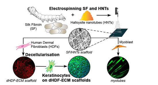
1. Introduction
2. Materials and Methods
3. Results
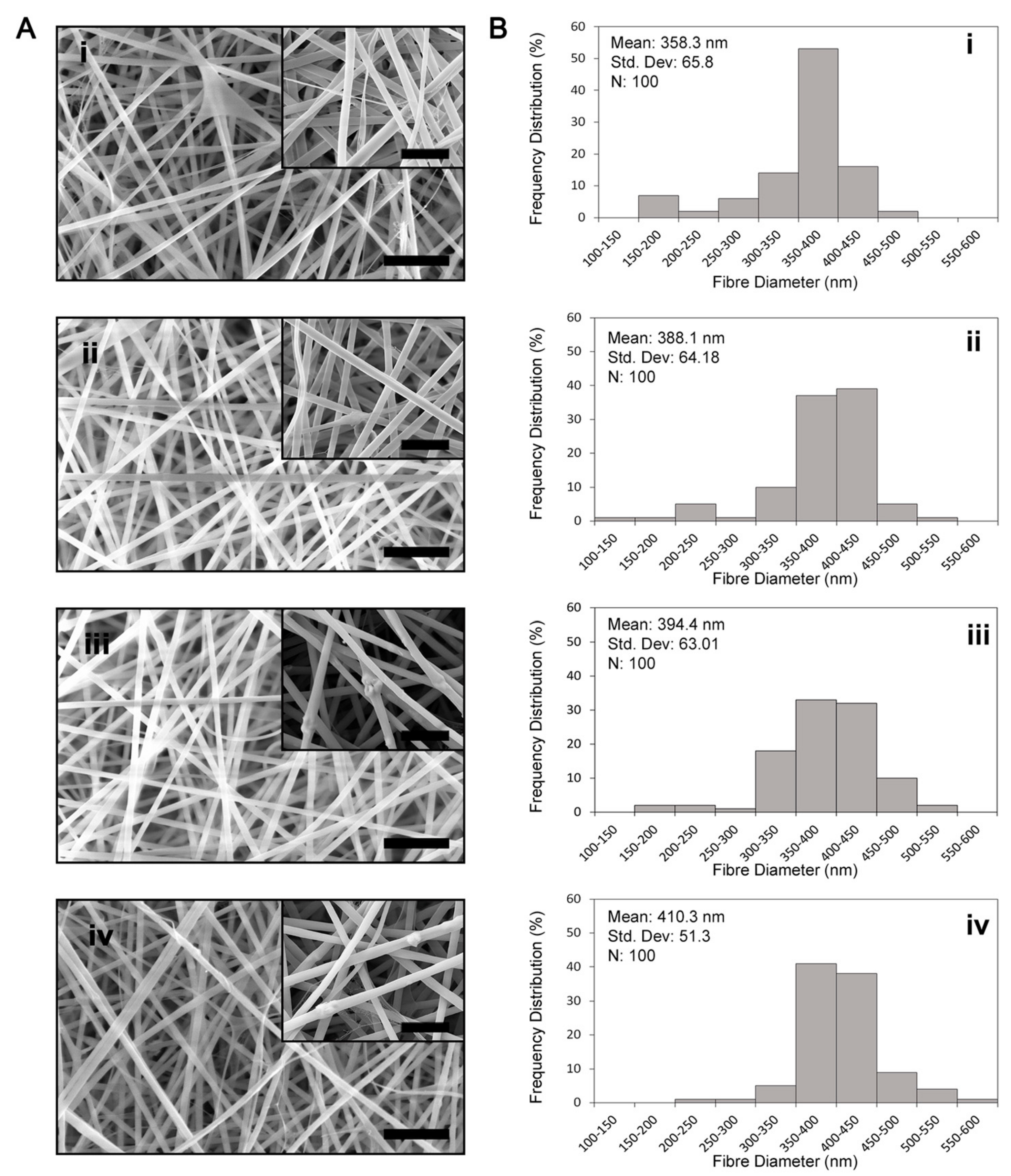
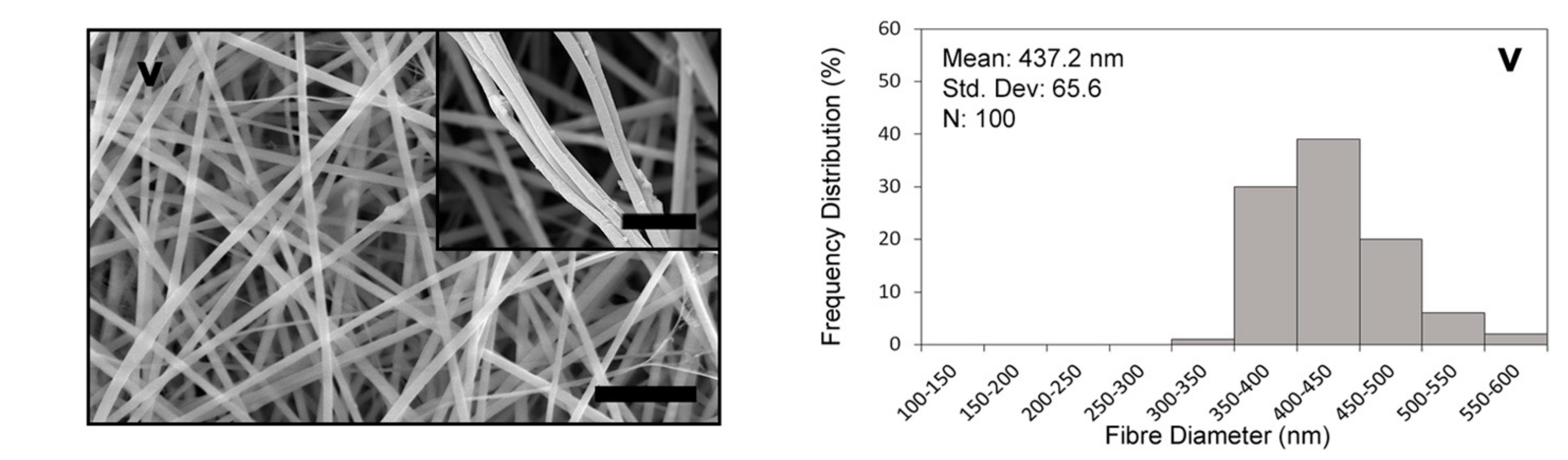
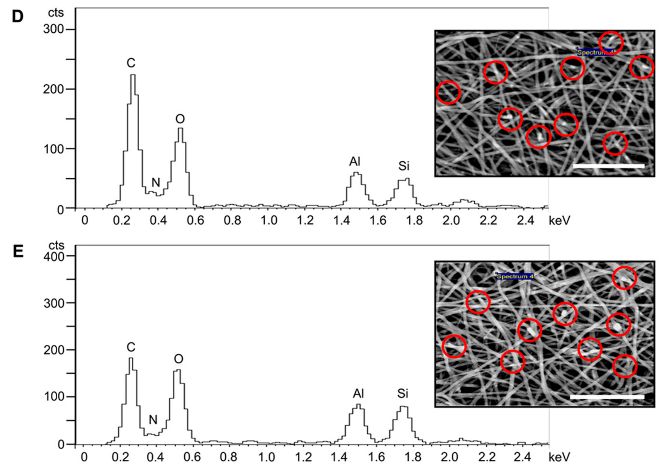
3.1. Fibre Morphology
3.2. BET Surface Area
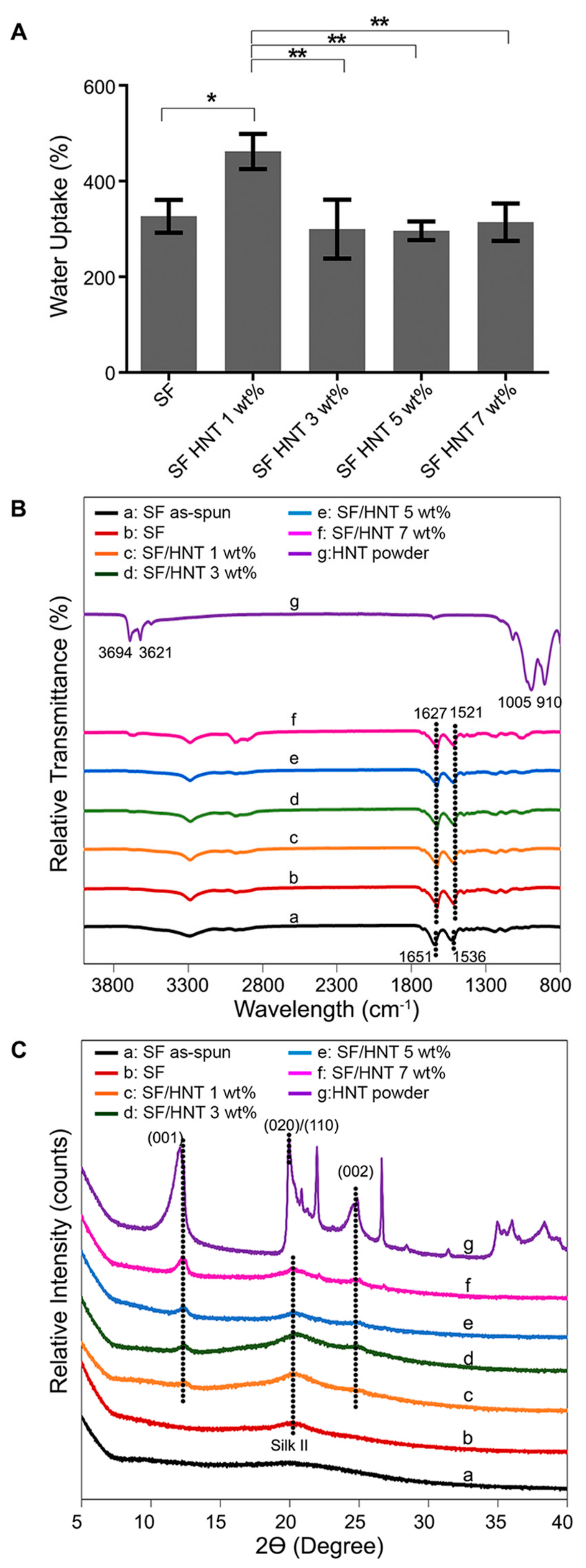
3.3. Contact Angle and Water Uptake Capacity (WUC)
3.4. FTIR Analysis
3.5. XRD Analysis
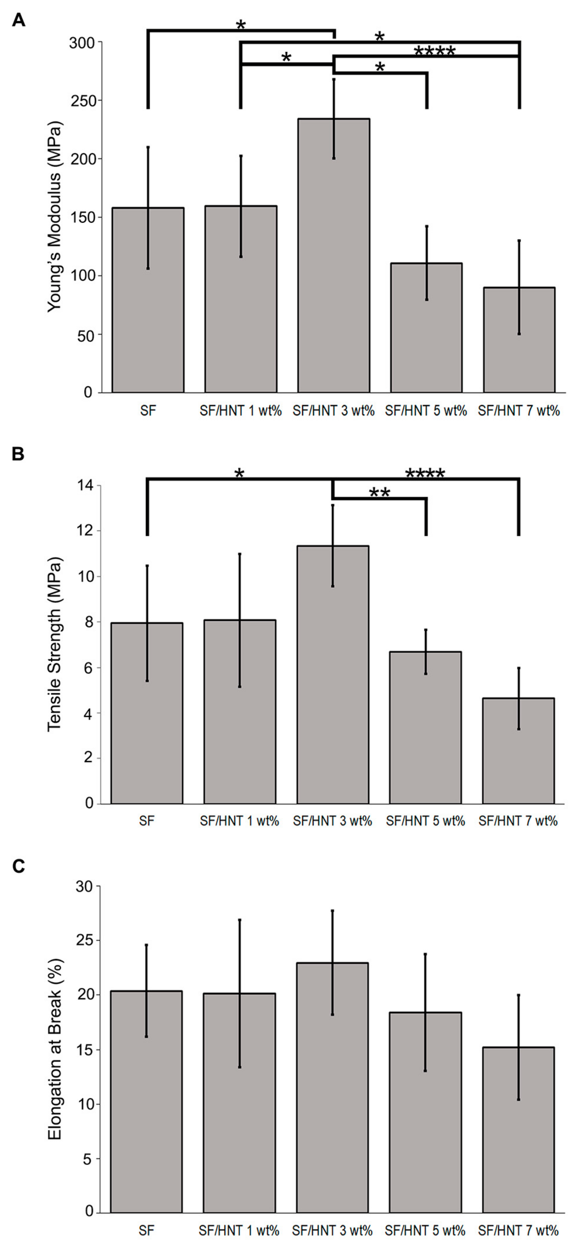
3.6. Mechanical Properties
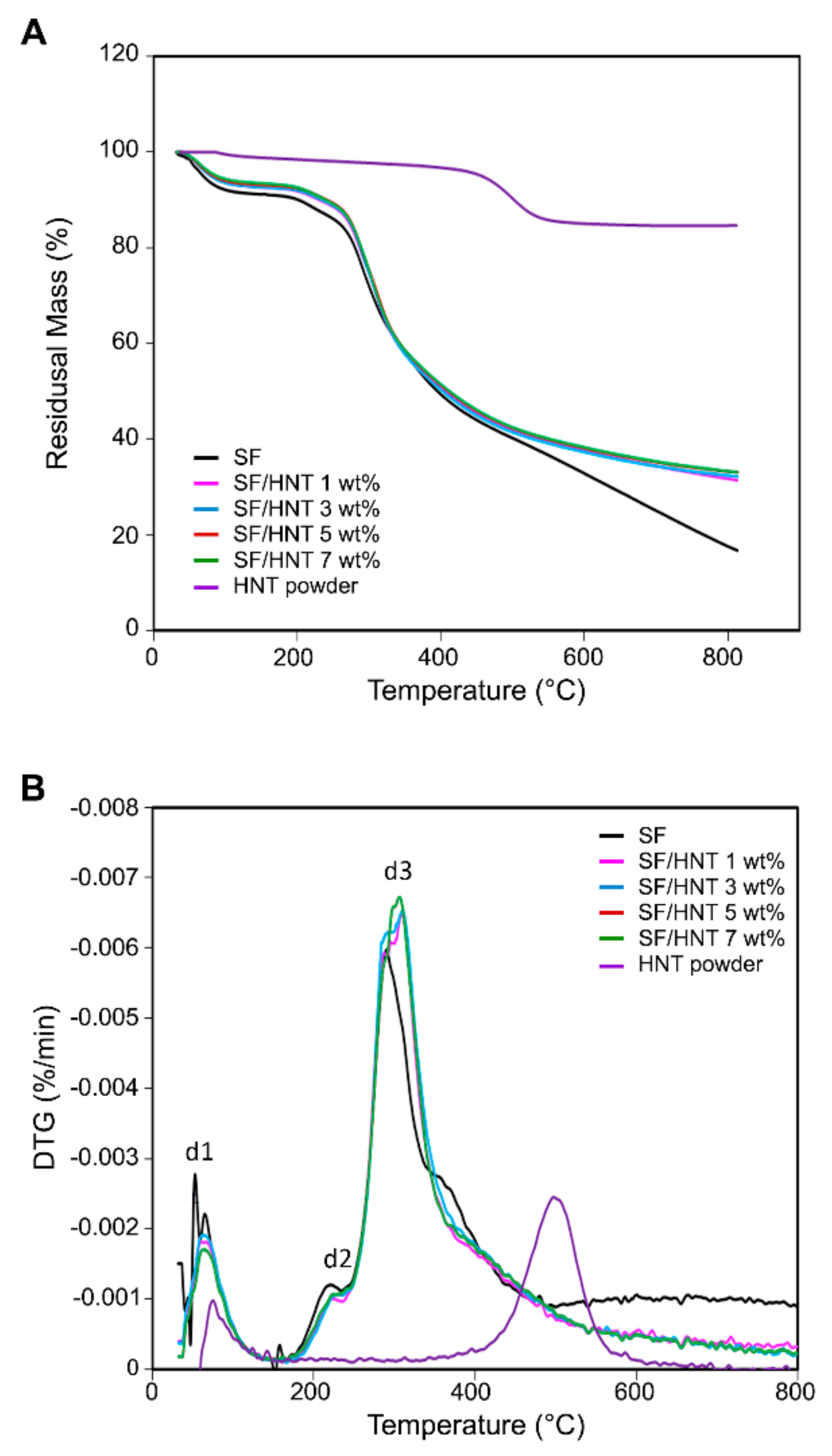
3.7. Thermal Stability
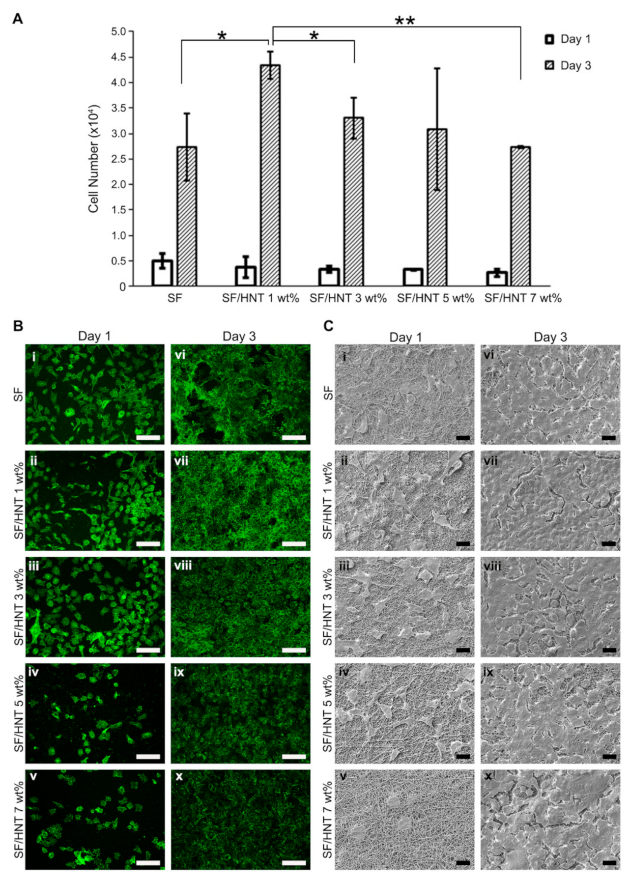
3.8. Fibroblast Growth on SF and SF/HNT Composite Scaffolds
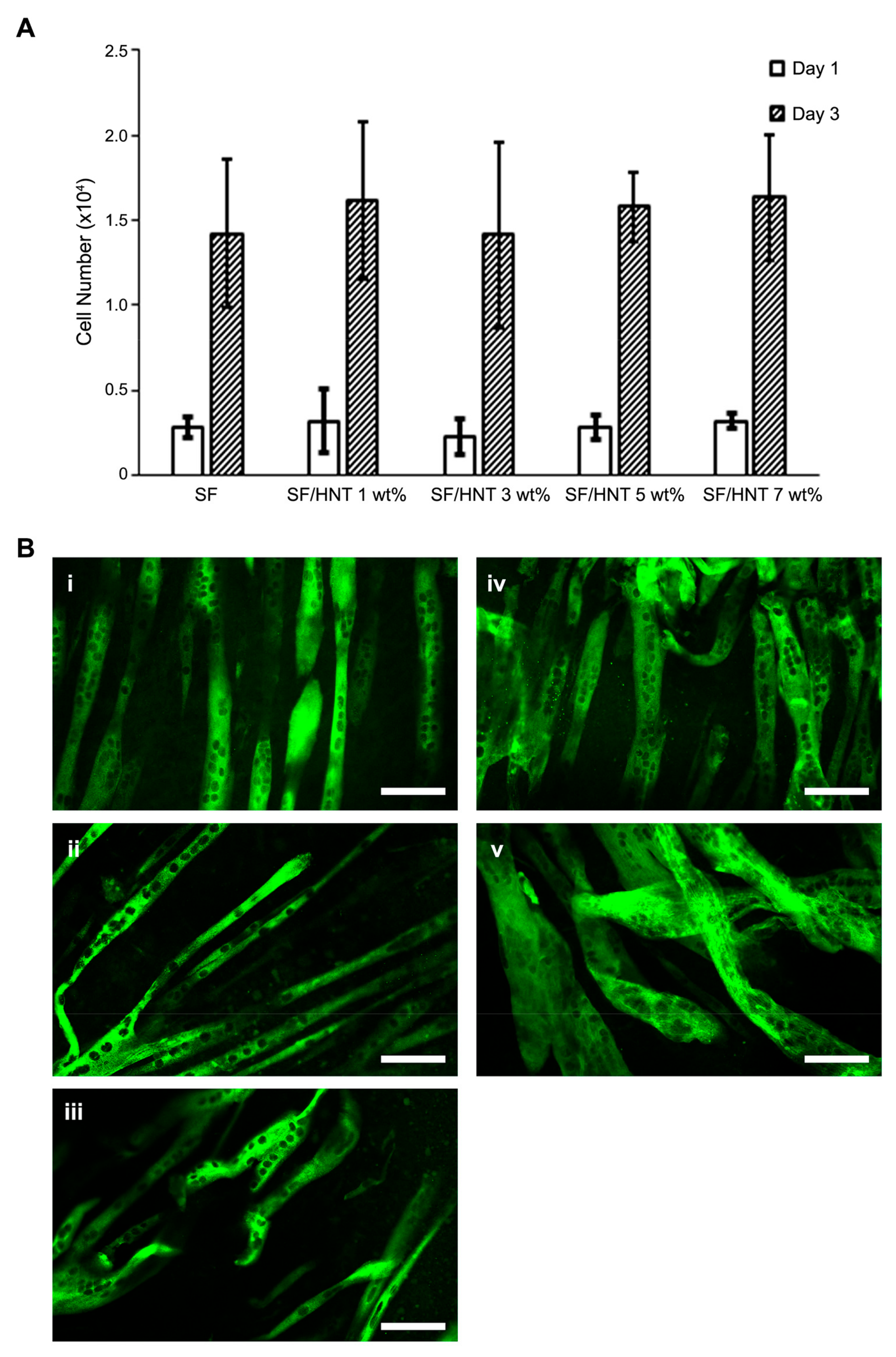
3.9. C2C12 Myoblasts Differentiate Differently on the Scaffolds
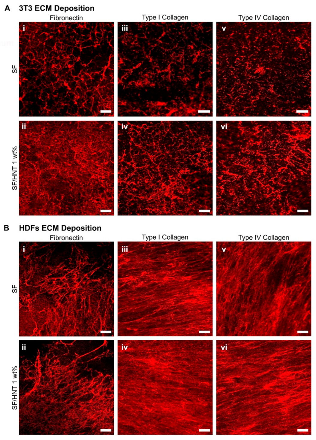
3.10. Fibroblasts Deposit ECM on the Scaffolds
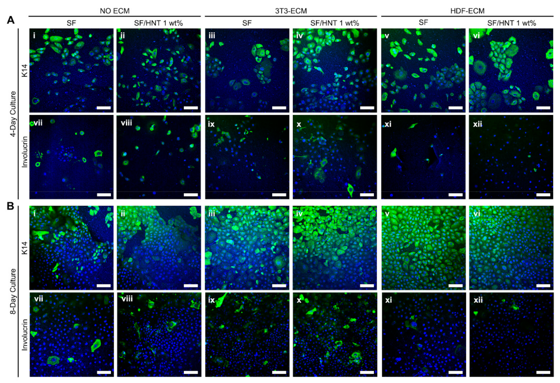
3.11. Primary Human Keratinocytes Remain Undifferentiated on ECM Functionalised Scaffolds
4. Discussion
5. Conclusions
Supplementary Materials
Author Contributions
Funding
Institutional Review Board Statement
Informed Consent Statement
Data Availability Statement
Acknowledgments
Conflicts of Interest
Abbreviations
References
- Rodriguez, M.J.; Brown, J.; Giordano, J.; Lin, S.J.; Omenetto, F.G.; Kaplan, D.L. Silk Based Bioinks for Soft Tissue Reconstruction Using 3-Dimensional (3d) Printing with in Vitro and in Vivo Assessments. Biomaterials 2017, 117, 105–115. [Google Scholar] [CrossRef] [PubMed] [Green Version]
- Pei, B.; Wang, W.; Fan, Y.; Wang, X.; Watari, F.; Li, X. Fiber-Reinforced Scaffolds in Soft Tissue Engineering. Regen. Biomater. 2017, 4, 257–268. [Google Scholar] [CrossRef] [PubMed]
- Bas, O.; Catelas, I.; De-Juan-Pardo, E.M.; Hutmacher, D.W. The Quest for Mechanically and Biologically Functional Soft Biomaterials Via Soft Network Composites. Adv. Drug Deliv. Rev. 2018, 132, 214–234. [Google Scholar] [CrossRef] [PubMed] [Green Version]
- Prabhakaran, M.P.; Ghasemi-Mobarakeh, L.; Ramakrishna, S. Electrospun Composite Nanofibers for Tissue Regeneration. J. Nanosci. Nanotechnol. 2011, 11, 3039–3057. [Google Scholar] [CrossRef]
- Jun, I.; Han, H.S.; Edwards, J.R.; Jeon, H. Electrospun Fibrous Scaffolds for Tissue Engineering: Viewpoints on Architecture and Fabrication. Int. J. Mol. Sci. 2018, 19, 745. [Google Scholar] [CrossRef] [Green Version]
- Manchineella, S.; Thrivikraman, G.; Khanum, K.K.; Ramamurthy, P.C.; Basu, B.; Govindaraju, T. Pigmented Silk Nanofibrous Composite for Skeletal Muscle Tissue Engineering. Adv. Healthc. Mater. 2016, 5, 1222–1232. [Google Scholar] [CrossRef]
- Gholipourmalekabadi, M.; Sapru, S.; Samadikuchaksaraei, A.; Reis, R.L.; Kaplan, D.L.; Kundu, S.C. Silk Fibroin for Skin Injury Repair: Where Do Things Stand? Adv. Drug Deliv. Rev. 2020, 153, 28–53. [Google Scholar] [CrossRef]
- Min, B.M.; Lee, G.; Kim, S.H.; Nam, Y.S.; Lee, T.S.; Park, W.H. Electrospinning of Silk Fibroin Nanofibers and Its Effect on the Adhesion and Spreading of Normal Human Keratinocytes and Fibroblasts In Vitro. Biomaterials 2004, 25, 1289–1297. [Google Scholar] [CrossRef]
- Chaturvedi, V.; Naskar, D.; Kinnear, B.F.; Grenik, E.; Dye, D.E.; Grounds, M.D.; Kundu, S.C.; Coombe, D.R. Silk Fibroin Scaffolds with Muscle-Like Elasticity Support in Vitro Differentiation of Human Skeletal Muscle Cells. J. Tissue Eng. Regen. Med. 2017, 11, 3178–3192. [Google Scholar] [CrossRef]
- Park, H.S.; Gong, M.S.; Park, J.H.; Moon, S.I.; Wall, I.B.; Kim, H.W.; Lee, J.H.; Knowles, J.C. Silk Fibroin-Polyurethane Blends: Physical Properties and Effect of Silk Fibroin Content on Viscoelasticity, Biocompatibility and Myoblast Differentiation. Acta Biomater. 2013, 9, 8962–8971. [Google Scholar] [CrossRef]
- Zhang, M.; Guo, B. Electroactive 3D Scaffolds Based on Silk Fibroin and Water-Borne Polyaniline for Skeletal Muscle Tissue Engineering. Macromol. Biosci. 2017, 17, 1700147. [Google Scholar] [CrossRef]
- Chouhan, D.; Mandal, B.B. Silk Biomaterials in Wound Healing and Skin Regeneration Therapeutics: From Bench to Bedside. Acta Biomater. 2020, 103, 24–51. [Google Scholar] [CrossRef]
- Zhang, W.; Chen, L.; Chen, J.; Wang, L.; Gui, X.; Ran, J.; Xu, G.; Zhao, H.; Zeng, M.; Ji, J.; et al. Silk Fibroin Biomaterial Shows Safe and Effective Wound Healing in Animal Models and a Randomized Controlled Clinical Trial. Adv. Healthc. Mater. 2017, 6, 1700121. [Google Scholar] [CrossRef]
- Ju, H.W.; Lee, O.J.; Lee, J.M.; Moon, B.M.; Park, H.J.; Park, Y.R.; Lee, M.C.; Kim, S.H.; Chao, J.R.; Ki, C.S.; et al. Wound Healing Effect of Electrospun Silk Fibroin Nanomatrix in Burn-Model. Int. J. Biol. Macromol. 2016, 85, 29–39. [Google Scholar] [CrossRef]
- Park, Y.R.; Ju, H.W.; Lee, J.M.; Kim, D.K.; Lee, O.J.; Moon, B.M.; Park, H.J.; Jeong, J.Y.; Yeon, Y.K.; Park, C.H. Three-Dimensional Electrospun Silk-Fibroin Nanofiber for Skin Tissue Engineering. Int. J. Biol. Macromol. 2016, 93 Pt B, 1567–1574. [Google Scholar] [CrossRef]
- Miguel, S.P.; Simoes, D.; Moreira, A.F.; Sequeira, R.S.; Correia, I.J. Production and Characterization of Electrospun Silk Fibroin Based Asymmetric Membranes for Wound Dressing Applications. Int. J. Biol. Macromol. 2019, 121, 524–535. [Google Scholar] [CrossRef]
- Ayutsede, J.; Gandhi, M.; Sukigara, S.; Ye, H.; Hsu, C.M.; Gogotsi, Y.; Ko, F. Carbon Nanotube Reinforced Bombyx mori Silk Nanofibers by the Electrospinning Process. Biomacromolecules 2006, 7, 208–214. [Google Scholar] [CrossRef]
- Dionigi, C.; Posati, T.; Benfenati, V.; Sagnella, A.; Pistone, A.; Bonetti, S.; Ruani, G.; Dinelli, F.; Padeletti, G.; Zamboni, R.; et al. A Nanostructured Conductive Bio-composite of Silk Fibroin-single Walled Carbon Nanotubes. J. Mater. Chem. B 2014, 2, 1424–1431. [Google Scholar] [CrossRef]
- Jiang, T.; Amadei, C.A.; Gou, N.; Lin, Y.; Lan, J.; Vecitis, C.D.; Gu, A.Z. Toxicity of Single-Walled Carbon Nanotubes (SWCNTs): Effect of Lengths, Functional Groups and Electronic Structures Revealed by a Quantitative Toxicogenomics Assay. Environ. Sci. Nano 2020, 7, 1348–1364. [Google Scholar] [CrossRef]
- Santos, A.C.; Ferreira, C.; Veiga, F.; Ribeiro, A.J.; Panchal, A.; Lvov, Y.; Agarwal, A. Halloysite Clay Nanotubes for Life Sciences Applications: From Drug Encapsulation to Bioscaffold. Adv. Colloid Interface Sci. 2018, 257, 58–70. [Google Scholar] [CrossRef]
- Satish, S.; Tharmavaram, M.; Rawtani, D. Halloysite Nanotubes as a Nature’s Boon for Biomedical Applications. Nanobiomedicine 2019, 6, 1849543519863625. [Google Scholar] [CrossRef] [PubMed] [Green Version]
- Santos, A.C.; Pereira, I.; Reis, S.; Veiga, F.; Saleh, M.; Lvov, Y. Biomedical Potential of Clay Nanotube Formulations and Their Toxicity Assessment. Expert Opin. Drug Deliv. 2019, 16, 1169–1182. [Google Scholar] [CrossRef] [PubMed]
- Liu, M.; Jia, Z.; Jia, D.; Zhou, C. Recent Advance in Research on Halloysite Nanotubes-Polymer Nanocomposite. Prog. Polymer. Sci. 2014, 39, 1498–1525. [Google Scholar] [CrossRef]
- Kausar, A. Review on Polymer/Halloysite Nanotube Nanocomposite. Polym. -Plast. Technol. Eng. 2017, 57, 548–564. [Google Scholar] [CrossRef]
- Ji, L.; Qiao, W.; Zhang, Y.; Wu, H.; Miao, S.; Cheng, Z.; Gong, Q.; Liang, J.; Zhu, A. A Gelatin Composite Scaffold Strengthened by Drug-Loaded Halloysite Nanotubes. Mater. Sci. Eng. C Mater. Biol. Appl. 2017, 78, 362–369. [Google Scholar] [CrossRef]
- Xue, J.; Niu, Y.; Gong, M.; Shi, R.; Chen, D.; Zhang, L.; Lvov, Y. Electrospun Microfiber Membranes Embedded with Drug-Loaded Clay Nanotubes for Sustained Antimicrobial Protection. ACS Nano 2015, 9, 1600–1612. [Google Scholar] [CrossRef]
- De Silva, R.T.; Dissanayake, R.K.; Mantilaka, M.; Wijesinghe, W.; Kaleel, S.S.; Premachandra, T.N.; Weerasinghe, L.; Amaratunga, G.A.J.; de Silva, K.M.N. Drug-Loaded Halloysite Nanotube-Reinforced Electrospun Alginate-Based Nanofibrous Scaffolds with Sustained Antimicrobial Protection. ACS Appl. Mater. Interfaces 2018, 10, 33913–33922. [Google Scholar] [CrossRef]
- Zhang, X.; Guo, R.; Xu, J.; Lan, Y.; Jiao, Y.; Zhou, C.; Zhao, Y. Poly(L-Lactide)/Halloysite Nanotube Electrospun Mats as Dual-Drug Delivery Systems and Their Therapeutic Efficacy in Infected Full-Thickness Burns. J. Biomater. Appl. 2015, 30, 512–525. [Google Scholar] [CrossRef]
- Qi, R.; Guo, R.; Zheng, F.; Liu, H.; Yu, J.; Shi, X. Controlled Release and Antibacterial Activity of Antibiotic-Loaded Electrospun Halloysite/Poly(Lactic-Co-Glycolic Acid) Composite Nanofibers. Colloids Surf. B Biointerfaces 2013, 110, 148–155. [Google Scholar] [CrossRef]
- Pavlinakova, V.; Fohlerova, Z.; Pavlinak, D.; Khunova, V.; Vojtova, L. Effect of Halloysite Nanotube Structure on Physical, Chemical, Structural and Biological Properties of Elastic Polycaprolactone/Gelatin Nanofibers for Wound Healing Applications. Mater. Sci. Eng. C Mater. Biol. Appl. 2018, 91, 94–102. [Google Scholar] [CrossRef]
- Chaturvedi, V.; Dye, D.E.; Kinnear, B.F.; van Kuppevelt, T.H.; Grounds, M.D.; Coombe, D.R. Interactions between Skeletal Muscle Myoblasts and Their Extracellular Matrix Revealed by a Serum Free Culture System. PLoS ONE 2015, 10, e0127675. [Google Scholar] [CrossRef]
- Wong, C.W.; LeGrand, C.F.; Kinnear, B.F.; Sobota, R.M.; Ramalingam, R.; Dye, D.E.; Raghunath, M.; Lane, E.B.; Coombe, D.R. In Vitro Expansion of Keratinocytes on Human Dermal Fibroblast-Derived Matrix Retains Their Stem-Like Characteristics. Sci. Rep. 2019, 9, 18561. [Google Scholar] [CrossRef] [Green Version]
- Rameshbabu, A.P.; Bankoti, K.; Datta, S.; Subramani, E.; Apoorva, A.; Ghosh, P.; Maity, P.P.; Manchikanti, P.; Chaudhury, K.; Dhara, S. Silk Sponges Ornamented with a Placenta-Derived Extracellular Matrix Augment Full-Thickness Cutaneous Wound Healing by Stimulating Neovascularization and Cellular Migration. ACS Appl. Mater. Interfaces 2018, 10, 16977–16991. [Google Scholar] [CrossRef]
- Harvestine, J.N.; Vollmer, N.L.; Ho, S.S.; Zikry, C.A.; Lee, M.A.; Leach, J.K. Extracellular Matrix-Coated Composite Scaffolds Promote Mesenchymal Stem Cell Persistence and Osteogenesis. Biomacromolecules 2016, 17, 3524–3531. [Google Scholar] [CrossRef]
- Sadr, N.; Pippenger, B.E.; Scherberich, A.; Wendt, D.; Mantero, S.; Martin, I.; Papadimitropoulos, A. Enhancing the Biological Performance of Synthetic Polymeric Materials by Decoration with Engineered, Decellularized Extracellular Matrix. Biomaterials 2012, 33, 5085–5093. [Google Scholar] [CrossRef]
- Rockwood, D.N.; Preda, R.C.; Yucel, T.; Wang, X.; Lovett, M.L.; Kaplan, D.L. Materials Fabrication from Bombyx Mori Silk Fibroin. Nat. Protoc. 2011, 6, 1612–1631. [Google Scholar] [CrossRef]
- Chen, Z.; Wei, B.; Mo, X.; Lim, C.T.; Ramakrishna, S.; Cui, F. Mechanical Properties of Electrospun Collagen–Chitosan Complex Single Fibers and Membrane. Mater. Sci. Eng. C 2009, 29, 2428–2435. [Google Scholar] [CrossRef]
- Leigh, I.M.; Purkis, P.E.; Whitehead, P.; Lane, E.B. Monospecific Monoclonal Antibodies to Keratin 1 Carboxy Terminal (Synthetic Peptide) and to Keratin 10 as Markers of Epidermal Differentiation. Br. J. Dermatol. 1993, 129, 110–119. [Google Scholar] [CrossRef]
- Purkis, P.E.; Steel, J.B.; Mackenzie, I.C.; Nathrath, W.B.; Leigh, I.M.; Lane, E.B. Antibody Markers of Basal Cells in Complex Epithelia. J. Cell Sci. 1990, 97 Pt 1, 39–50. [Google Scholar] [CrossRef]
- Schindelin, J.; Arganda-Carreras, I.; Frise, E.; Kaynig, V.; Longair, M.; Pietzsch, T.; Preibisch, S.; Rueden, C.; Saalfeld, S.; Schmid, B.; et al. Fiji: An Open-Source Platform for Biological-Image Analysis. Nat. Methods 2012, 9, 676–682. [Google Scholar] [CrossRef] [Green Version]
- Lu, Q.; Zhang, B.; Li, M.; Zuo, B.; Kaplan, D.L.; Huang, Y.; Zhu, H. Degradation Mechanism and Control of Silk Fibroin. Biomacromolecules 2011, 12, 1080–1086. [Google Scholar] [CrossRef] [PubMed] [Green Version]
- Kim, S.H.; Nam, Y.S.; Lee, T.S.; Park, W.H. Silk Fibroin Nanofiber. Electrospinning, Properties, and Structure. Polym. J. 2003, 35, 185–190. [Google Scholar] [CrossRef]
- Kurczewska, J.; Pecyna, P.; Ratajczak, M.; Gajęcka, M.; Schroeder, G. Halloysite Nanotubes as Carriers of Vancomycin in Alginate-based Wound Dressing. Saudi Pharm. J. 2017, 25, 911–920. [Google Scholar] [CrossRef] [PubMed]
- Luo, C.; Zou, Z.; Luo, B.; Wen, W.; Li, H.; Liu, M.; Zhou, C. Enhanced Mechanical Properties and Cytocompatibility of Electrospun Poly(L-Lactide) Composite Fiber Membranes Assisted by Polydopamine-Coated Halloysite Nanotubes. Appl. Surf. Sci. 2016, 369, 82–91. [Google Scholar] [CrossRef]
- Selvaraj, S.; Fathima, N.N. Fenugreek Incorporated Silk Fibroin Nanofibers-a Potential Antioxidant Scaffold for Enhanced Wound Healing. ACS Appl. Mater. Interfaces 2017, 9, 5916–5926. [Google Scholar] [CrossRef]
- Dong, Y.; Marshall, J.; Haroosh, H.J.; Mohammadzadehmoghadam, S.; Liu, D.; Qi, X.; Lau, K.-T. Polylactic Acid (Pla)/Halloysite Nanotube (Hnt) Composite Mats: Influence of HNT Content and Modification. Compos. Part A Appl. Sci. Manuf. 2015, 76, 28–36. [Google Scholar] [CrossRef] [Green Version]
- Nitya, G.; Nair, G.T.; Mony, U.; Chennazhi, K.P.; Nair, S.V. In Vitro Evaluation of Electrospun Pcl/Nanoclay Composite Scaffold for Bone Tissue Engineering. J. Mater. Sci. Mater. Med. 2012, 23, 1749–1761. [Google Scholar] [CrossRef]
- Li, C.; Vepari, C.; Jin, H.J.; Kim, H.J.; Kaplan, D.L. Electrospun Silk-Bmp-2 Scaffolds for Bone Tissue Engineering. Biomaterials 2006, 27, 3115–3124. [Google Scholar] [CrossRef]
- Liu, H.; Li, X.; Zhou, G.; Fan, H.; Fan, Y. Electrospun Sulfated Silk Fibroin Nanofibrous Scaffolds for Vascular Tissue Engineering. Biomaterials 2011, 32, 3784–3793. [Google Scholar] [CrossRef]
- Fan, L.; Wang, H.; Zhang, K.; He, C.; Cai, Z.; Mo, X. Regenerated Silk Fibroin Nanofibrous Matrices Treated with 75% Ethanol Vapor for Tissue-Engineering Applications. J. Biomater. Sci. Polym. Ed. 2012, 23, 497–508. [Google Scholar] [CrossRef]
- Sumer Gaaz, T.; Bakar Sulong, A.; Kadhum, A.A.H.; Nassir, M.H.; Al-Amiery, A.A. Absolute Variation of the Mechanical Characteristics of Halloysite Reinforced Polyurethane Nanocomposites Complemented by Taguchi and ANOVA Approaches. Results Phys. 2017, 7, 3287–3300. [Google Scholar] [CrossRef]
- Makaremi, M.; De Silva, R.T.; Pasbakhsh, P. Electrospun Nanofibrous Membranes of Polyacrylonitrile/Halloysite with Superior Water Filtration Ability. J. Phys. Chem. C 2015, 119, 7949–7958. [Google Scholar] [CrossRef]
- Fu, S.Z.; Wang, X.H.; Guo, G.; Shi, S.; Fan, M.; Liang, H.; Luo, F.; Qian, Z.Y. Preparation and Properties of Nano-Hydroxyapatite/Pcl-Peg-Pcl Composite Membranes for Tissue Engineering Applications. J. Biomed. Mater. Res. B Appl. Biomater. 2011, 97, 74–83. [Google Scholar] [CrossRef]
- Huang, Z.-X.; Liu, X.; Wong, S.-C.; Qu, J.-P. Electrospinning Polyvinylidene fluoride/expanded Graphite Composite Membranes as High Efficiency and Reusable Water Harvester. Mater. Lett. 2017, 202, 78–81. [Google Scholar] [CrossRef]
- Govindasamy, K.; Dahlan, N.A.; Janarthanan, P.; Goh, K.L.; Chai, S.P.; Pasbakhsh, P. Electrospun chitosan/polyethylene-oxide (PEO)/halloysites (HAL) Membranes for Bone Regeneration Applications. Appl. Clay Sci. 2020, 190, 105601. [Google Scholar] [CrossRef]
- De Silva, R.T.; Pasbakhsh, P.; Goh, K.L.; Chai, S.P.; Chen, J. Synthesis and Characterisation of Poly (Lactic Acid)/Halloysite Bionanocomposite Films. J. Compos. Mater. 2014, 48, 3705–3717. [Google Scholar] [CrossRef]
- Švachová, V.; Khunová, V.; Pavliňák, D.; Fohlerová, Z.; Vojtová, L. The Effect of Halloysite on Structure and Properties of Polycaprolactone/Gelatin Nanofibers. Polym. Eng. Sci. 2017, 57, 506–512. [Google Scholar] [CrossRef]
- Zhou, W.Y.; Guo, B.; Liu, M.; Liao, R.; Rabie, A.B.M.; Jia, D. Poly(Vinyl Alcohol)/Halloysite Nanotubes Bionanocomposite Films: Properties and in Vitro Osteoblasts and Fibroblasts Response. J. Biomed. Mater. Res. A 2009, 93, 1574–1587. [Google Scholar] [CrossRef]
- Pan, H.; Zhang, Y.; Hang, Y.; Shao, H.; Hu, X.; Xu, Y.; Feng, C. Significantly Reinforced Composite Fibers Electrospun from Silk Fibroin/Carbon Nanotube Aqueous Solutions. Biomacromolecules 2012, 13, 2859–2867. [Google Scholar] [CrossRef]
- Abdullah, Z.W.; Dong, Y. Preparation and Characterisation of Poly(Vinyl) Alcohol (Pva)/Starch (St)/Halloysite Nanotube (Hnt) Nanocomposite Films as Renewable Materials. J. Mater. Sci. 2017, 53, 3455–3469. [Google Scholar] [CrossRef] [Green Version]
- Kim, C.H.; Khil, M.S.; Kim, H.Y.; Lee, H.U.; Jahng, K.Y. An Improved Hydrophilicity via Electrospinning for Enhanced Cell Attachment and Proliferation. J. Biomed. Mater. Res. B Appl. Biomater. 2006, 78, 283–290. [Google Scholar] [CrossRef]
- Liu, M.; Dai, L.; Shi, H.; Xiong, S.; Zhou, C. In Vitro Evaluation of Alginate/Halloysite Nanotube Composite Scaffolds for Tissue Engineering. Mater. Sci. Eng. C Mater. Biol. Appl. 2015, 49, 700–712. [Google Scholar] [CrossRef]
- Shin, Y.C.; Lee, J.H.; Jin, L.; Kim, M.J.; Kim, Y.J.; Hyun, J.K.; Jung, T.G.; Hong, S.W.; Han, D.W. Stimulated Myoblast Differentiation on Graphene Oxide-Impregnated Plga-Collagen Hybrid Fibre Matrices. J. Nanobiotechnology 2015, 13, 21. [Google Scholar] [CrossRef] [Green Version]
- Gilmore, K.J.; Kita, M.; Han, Y.; Gelmi, A.; Higgins, M.J.; Moulton, S.E.; Clark, G.M.; Kapsa, R.; Wallace, G.G. Skeletal Muscle Cell Proliferation and Differentiation on Polypyrrole Substrates Doped with Extracellular Matrix Components. Biomaterials 2009, 30, 5292–5304. [Google Scholar] [CrossRef]
- Chou, K.C.; Chen, C.T.; Cherng, J.H.; Li, M.C.; Wen, C.C.; Hu, S.I.; Wang, Y.W. Cutaneous Regeneration Mechanism of β-Sheet Silk Fibroin in a Rat Burn Wound Healing Model. Polymers 2021, 13, 3537. [Google Scholar] [CrossRef]
- Chester, D.; Brown, A.C. The Role of Biophysical Properties of Provisional Matrix Proteins in Wound Repair. Matrix Biol. 2017, 60–61, 124–140. [Google Scholar] [CrossRef]
- Matsuura-Hachiya, Y.; Arai, K.Y.; Muraguchi, T.; Sasaki, T.; Nishiyama, T. Type IV Collagen Aggregates Promote Keratinocyte Proliferation and Formation of Epidermal Layer in Human Skin Equivalents. Exp. Dermatol. 2018, 27, 443–448. [Google Scholar] [CrossRef]
- Marinkovic, M.; Block, T.J.; Rakian, R.; Li, Q.; Wang, E.; Reilly, M.A.; Dean, D.D.; Chen, X.D. One Size Does Not Fit All: Developing a Cell-Specific Niche for in Vitro Study of Cell Behavior. Matrix Biol. 2016, 52–54, 426–441. [Google Scholar] [CrossRef] [Green Version]
- Sellaro, T.L.; Ravindra, A.K.; Stolz, D.B.; Badylak, S.F. Maintenance of Hepatic Sinusoidal Endothelial Cell Phenotype in Vitro Using Organ-Specific Extracellular Matrix Scaffolds. Tissue Eng. 2007, 13, 2301–2310. [Google Scholar] [CrossRef]

| Sample | BET Surface Area (m2/g) |
|---|---|
| SF | 4.47 1 |
| SF/HNT 1 wt% | 5.14 |
| SF/HNT 3 wt% | 8.06 |
| SF/HNT 5 wt% | 8.43 |
| SF/HNT 7 wt% | 9.06 |
| Sample | Water Contact Angle (Degrees) |
|---|---|
| SF | 64.23°± 4.01° |
| SF/HNT 1 wt% | 57.52° ± 6.73° * |
| SF/HNT 3 wt% | 65.73° ± 7.29° |
| SF/HNT 5 wt% | 66.33° ± 5.46° |
| SF/HNT 7 wt% | 70.76° ± 4.82° * |
| Sample | TGA | DTG | |||
|---|---|---|---|---|---|
| T 10% a | T 50% a | Td1 c | Td2 c | Td3 c | |
| SF | 201.65 b | 395.3 | 68.22 | 222.41 | 290.65 |
| HNT particles | – | – | – | – | 499.56 |
| SF/HNT 1 wt% | 230.84 | 407.6 | 70.97 | 231.37 | 311.54 |
| SF/HNT 3 wt% | 240.63 | 412.68 | 70.85 | 234.35 | 312.42 |
| SF/HNT 5 wt% | 239.88 | 409.3 | 69.9 | 228.26 | 309.26 |
| SF/HNT 7 wt% | 234.52 | 408.4 | 68 | 226.49 | 308.57 |
Publisher’s Note: MDPI stays neutral with regard to jurisdictional claims in published maps and institutional affiliations. |
© 2022 by the authors. Licensee MDPI, Basel, Switzerland. This article is an open access article distributed under the terms and conditions of the Creative Commons Attribution (CC BY) license (https://creativecommons.org/licenses/by/4.0/).
Share and Cite
Mohammadzadehmoghadam, S.; LeGrand, C.F.; Wong, C.-W.; Kinnear, B.F.; Dong, Y.; Coombe, D.R. Fabrication and Evaluation of Electrospun Silk Fibroin/Halloysite Nanotube Biomaterials for Soft Tissue Regeneration. Polymers 2022, 14, 3004. https://doi.org/10.3390/polym14153004
Mohammadzadehmoghadam S, LeGrand CF, Wong C-W, Kinnear BF, Dong Y, Coombe DR. Fabrication and Evaluation of Electrospun Silk Fibroin/Halloysite Nanotube Biomaterials for Soft Tissue Regeneration. Polymers. 2022; 14(15):3004. https://doi.org/10.3390/polym14153004
Chicago/Turabian StyleMohammadzadehmoghadam, Soheila, Catherine F. LeGrand, Chee-Wai Wong, Beverley F. Kinnear, Yu Dong, and Deirdre R. Coombe. 2022. "Fabrication and Evaluation of Electrospun Silk Fibroin/Halloysite Nanotube Biomaterials for Soft Tissue Regeneration" Polymers 14, no. 15: 3004. https://doi.org/10.3390/polym14153004
APA StyleMohammadzadehmoghadam, S., LeGrand, C. F., Wong, C.-W., Kinnear, B. F., Dong, Y., & Coombe, D. R. (2022). Fabrication and Evaluation of Electrospun Silk Fibroin/Halloysite Nanotube Biomaterials for Soft Tissue Regeneration. Polymers, 14(15), 3004. https://doi.org/10.3390/polym14153004