1. Introduction
Ionomers are polymers whose volumetric properties are influenced by interactions between ionic substituent groups covalently linked to the polymeric skeleton, usually in low molar ratio (up to 15% molar), and located in discrete regions of the polymeric material, named as ionic aggregates [
1,
2]. Some morphological models are found in the literature to elucidate the microstructure of ionomers, and the most accepted being: (a) model of multiplets and clusters [
3], according to which ionic species incorporated in the polymeric structure establish interactions in discrete regions, resulting in the formation of ionic aggregates (multiplets) that interact with each other forming clusters; (b) model of order–disorder transitions of ionic clusters [
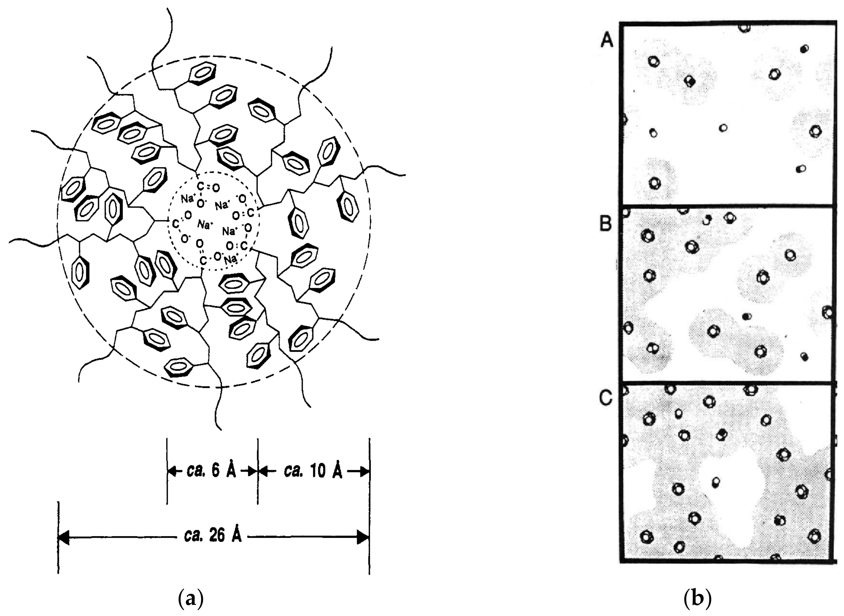
4], in which the clusters suffer first-order transitions during heating at a temperature lower than the melting temperature of the polymer, called temperature of order–disorder; and (c) model of restriction of the mobility of polymeric chains neighboring the multiplets, where it is considered that the chain segments close to the ionic multiplets have lower mobility compared to the chain segments further away from the multiplets, i.e., each multiplet is surrounded by a region of restricted mobility of polymer chain, as if it were a “skin” (
Figure 1a). In the last model, known as the EHM model, due to the initial letters of the authors’ names, it was also stated that the greater the ionic content, the greater the number of multiplets distributed in the molecular structure of the ionomer. Therefore, in the EHM model, due to the increase in the density of ions present, the occurrence of overlapping regions of neighboring restricted mobility increases due to the decrease in the distance between the multiplets, which may result in the formation of clusters (
Figure 1b) [
2]. Morphological models show that ionomers, as a result of their very nature, are supramolecular structures [
5] because they have crossover points of physical nature, established by ionic groups (multiplets), which are thermally reversible.
Polymeric ionomers offer a wide spectrum of opportunities for researchers to develop new materials, since the specific behaviors present in these materials (high flexibility, good mechanical properties, excellent adhesion with ceramic materials and regeneration capacity after damage at moderate temperatures), resulting from their molecular structures, enable the investigation of several properties, such as physical, mechanical, molecular dynamics, thermo-dynamic-mechanical, dielectric, thermal and optical, among others [
6,
7,
8,
9,
10]. Many scientific works explore the concept of piezoelectricity and ferroelectricity using the solid solution of lead titanate and lead zirconate, PbTiO
3 and PbZrO
3, respectively. Based on this solid solution, a ceramic system of perovskite structure is obtained, which is also known as lead zirconate titanate [Pb(Zr
0,52Ti
0,48)O
3] or PZT [
7,
11]. Piezoelectric active PZT exhibits excellent strain reliability and survivability over a large temperature range, from the temperature of liquid nitrogen to the cure temperature of high-performance polymer matrix composite materials, making it worthwhile for in situ health monitoring of aging aircraft fleet throughout the service life [
11]. The combination of the properties of polymeric ionomers and piezoelectric ceramic materials, as a perovskite-structured compound, can provide several materials, which are used to the development of smart materials, photovoltaic cells, piezoelectric sensors and biomaterials [
7,
8,
9].
Although PZT has excellent piezoelectric properties, being widely used in transducers, actuators and sensors [
12,
13], there is a limitation in designing devices exclusively made of this material with complex geometric shapes due to the fragility of ceramic materials. A solution to overcome this limitation, due to the ease of processing (they can be designed in complex geometric shapes), feasibility of reuse (they can be cast and molded several times) and ductility (they can undergo large deformations), is to disperse the ceramic particles in ductile thermoplastic polymeric materials capable of providing attractive mechanical characteristics to different applications (such as increased ductility, improved formability, etc.) without penalizing the sensing capacity of the obtained composite [
12]. For instance, PZT has been used in the preparation of composites with the copolymer poly(ethylene-co-methacrylic acid), EMAA, as well as composites employing EMAA-derived ionomers with their acid groups partially neutralized with zinc ions in order to develop sensing materials [
12,
14]. Given the recognized PZT toxicity, brittleness and relatively high cost [
14], blended particulate PZT with thermoplastic polyvinylidene fluoride (PVDF) polymer gives rise to the first piezo film sensor. Regarding the usage of thermoplastic polymers for sensor development, polyvinylidene fluoride, or PVDF, is a widely applied material, as it has superior piezoelectric characteristics/properties compared to other polymers; its piezoelectricity coefficient can reach up to 7 pC/N [
15], in addition to being used to obtain efficient triboelectric nanogenerators by improving the polarization of their surface [
16]. Moreover, regarding the aircraft applications, it is noteworthy that the materials most used in aeronautical structures are aluminum alloys with density around 2760 kg/m
3 [
17] and composite materials of epoxy resin reinforced with carbon fibers with density approximately 1300 kg/m
3 [
18]. Despite its good piezoelectric properties, the piezoelectric thermoplastic polymer PVDF shows density between 1760 and 1900 kg/m
3 [
19,
20], which is lower than aluminum alloys, but it is higher than composites of epoxy resin reinforced with carbon fibers. Thus, it is not considered appropriate that the sensor density is higher than the densities of materials used in aeronautical structures that have large areas, such as panels used in fuselages and wings, which would have to be covered with the piezoelectric composite film. Designing sensors based on piezoelectric composites that combine satisfactory sensing properties with ease of processing and adequate mechanical properties, as well as good flexibility and ability to regenerate damage on a microscale, remains a huge challenge for different fields [
14].
Considering the scenario described above, the main motivation of the present work is to monitor structural damage, initially, in aeronautical structures. Thus, flexible films of composites (SNaPZT#) were developed from the regenerable polymer matrix (healing) of Surlyn
® 8940 ionomer (DuPont
TM), based on ethylene/methacrylic acid copolymer, with 5.4 mol% of methacrylic acid groups and 30% of these groups neutralized by sodium ions (Na
+)—defined as SNa0 in the present work—and PZT particles (connectivity 2–3) in volume fractions (#) of 1, 3, 5 and 7%. The choice of PZT volume fractions followed the preliminary requirement that establishes a final sensor density, which is lower or at least close to the density of the materials used in aeronautical structures. Since the application of composites based on epoxy resin/carbon fibers has been increasing in the aeronautical segment [
21], it was chosen as a model in the present work to develop and characterize flexible composite films with density values lower than 1500 kg/m
3. Thus, it was chosen not to exceed 7% in volume fraction of PZT. In other words, in the present work, the extremely flexible PZT particle-filled ethylene/methacrylic acid copolymer ionomer films are proposed, manufactured and tested to comply with physical, mechanical and thermomechanical requirements for acting as efficient strain and structural monitoring sensors in aircrafts. Therefore, as a first step in this article, it was investigated how the PZT particles can influence the thermal and mechanical properties of the EMAA
−Na
+ Ionomer flexible film by using results from scanning electron microscopy (SEM), X-ray diffraction (XRD), dynamic mechanical analysis (DMA) and mechanical tensile tests. In the next paper, not only electrical but also thermal behavior of the flexible composite films will be thoroughly investigated, evaluating their potentialities and limitations to be used as a damage sensor in aeronautical structures.
As scientific contributions, the present work brings relevant data and results related to the new composite films. Thus, it is possible to highlight that the composite possesses very low density, very low particulate volumetric fraction, homogeneous filler distribution, high filler dispersion, high adhesiveness to the substrate and easy forming to contours and corners, in addition to extrinsic self-healing potentialities.
3. Results and Discussion
3.1. Analysis of PZT Particles via X-ray and SEM
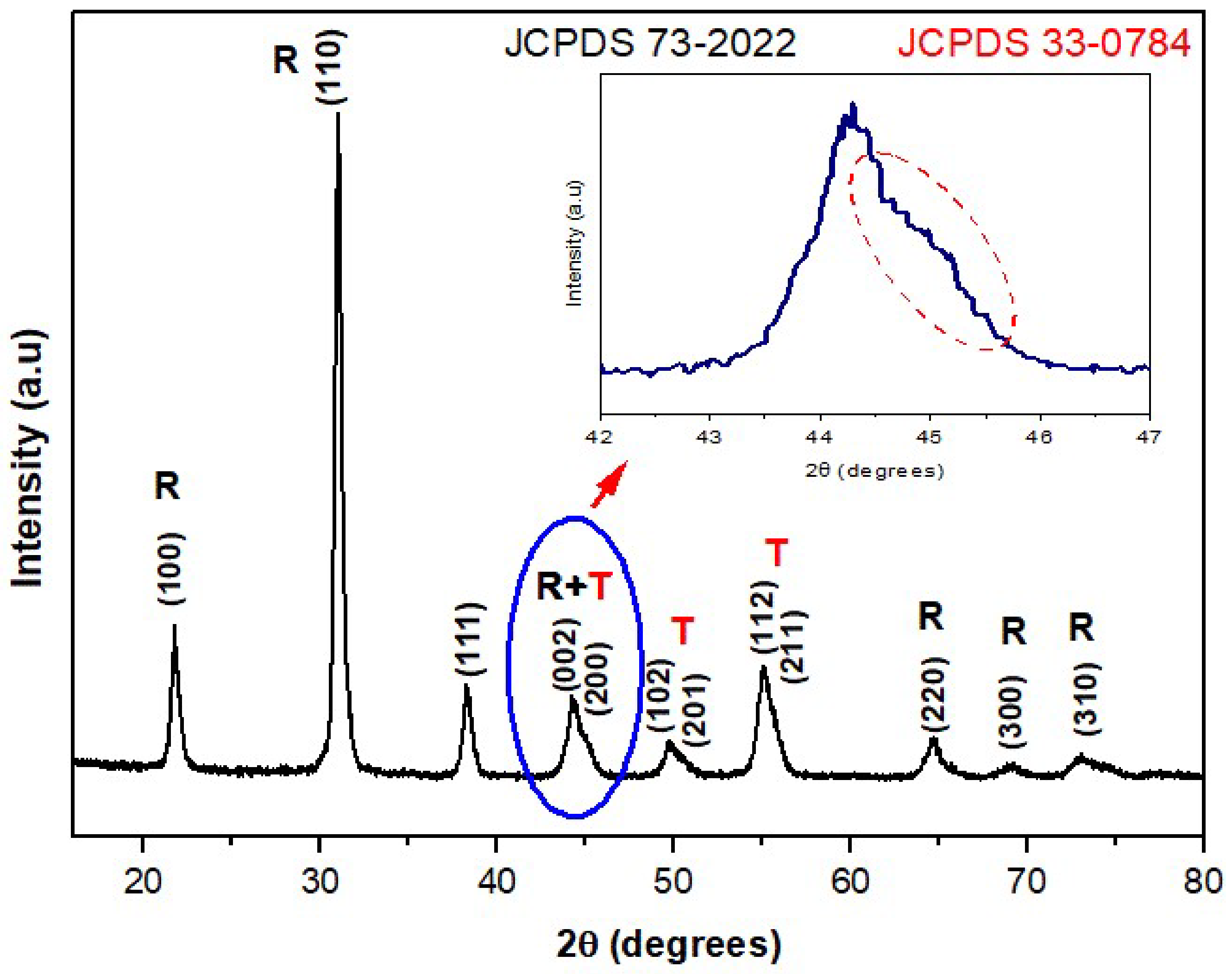
X-ray diffraction was employed to investigate the crystalline phase of PZT particles. As shown in
Figure 4, the XRD pattern of the PZT powder indicates the coexistence of PZT in the tetragonal phase (JCPDS file n
o 33-0784) and rhombohedral phase (JCPDS file n
o 73-2022). These results corroborate ones reported by James, Mishra et al. and Zak et al. [
12,
22,
23], where a pattern of diffraction of X-ray for the PZT particles, Pb(Zr
0,52Ti
0,48)O
3, was observed, with the coexistence of diffraction peaks related to the rhombohedral phase (200) and to tetragonal phase (002) and (200) in the same region of 2θ between 42° and 47°, as shown in
Figure 4, serving as evidence of the morphotropic phase boundary region (MPB) [
22,
23].
The coexistence of tetragonal phases (T) and rhombohedral phases (R) was confirmed by the X-ray graphic in
Figure 4 because, as observed by Singh et al. [
24] and by James [
12], in the same graphic, there is a presence of a doublet (superposition of two peaks R + T), in the region of 2θ between 44° and 47°, which is related mainly to the tetragonal phase. However, there is also the contribution of the peak in the direction (200) related to the rhombohedral phase.
Scientific investigations showed that the piezoelectric properties of the PZT particles are improved when there is a coexistence of the tetragonal phase (T) and rhombohedral phase (R) in the morphotropic phase boundary region. This behavior was observed in PZT particles with molar composition of Zr equal to 0.52 [
25]. In fact, this is explained due to the presence of a higher number of possible directions for the ferroelectric polarizations present simultaneously when there is a coexistence of phases R and T, there being six directions in phase T and eight directions in phase R [
22,
26]. It is important to note that the authors assigned the increment in the electromechanical response of PZT to the instability of phase T, in terms of the temperature, in the morphotropic phase boundary region.
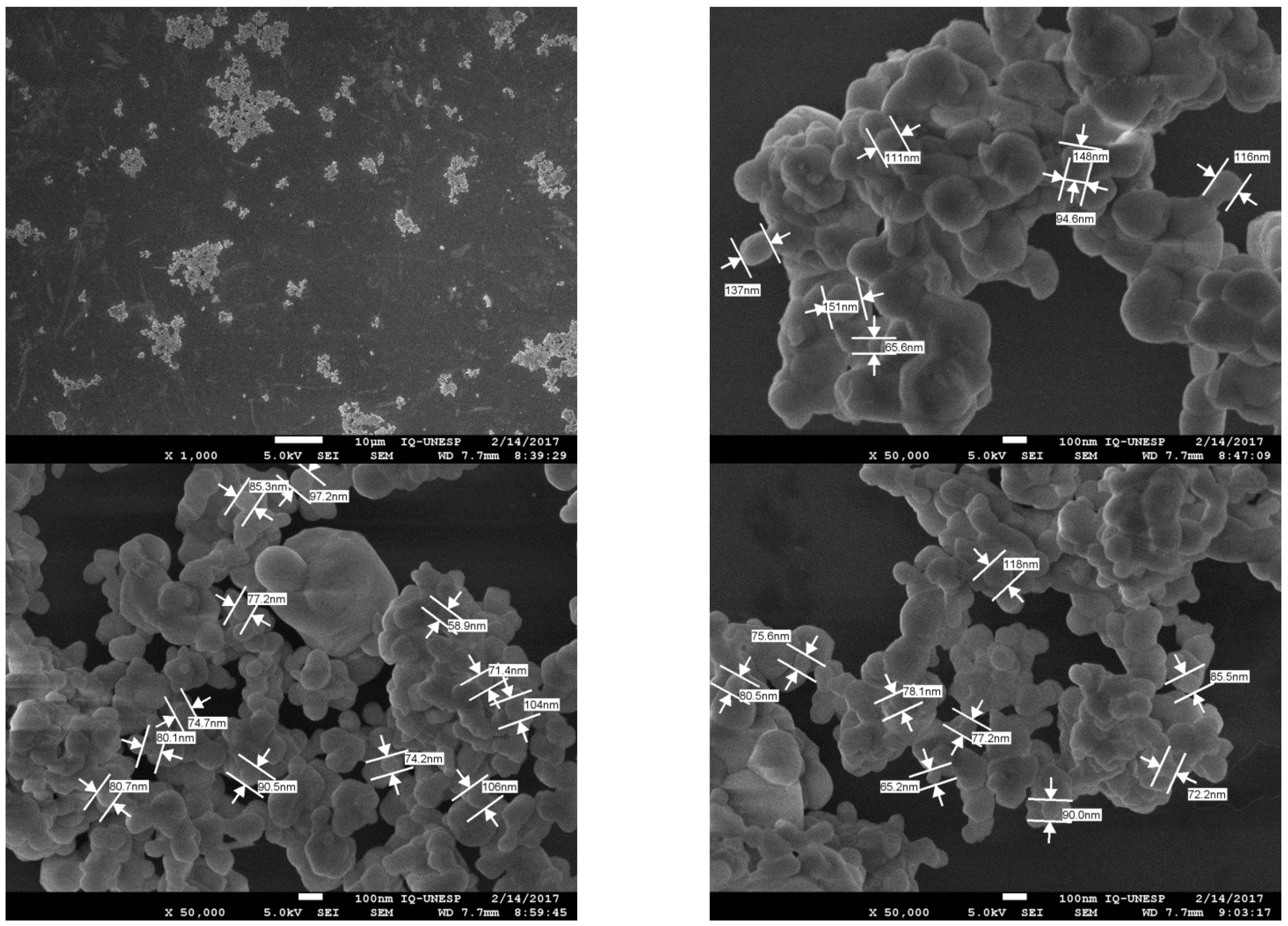
Considering the SEM analyses, it was observed that the PZT particles initially form clusters, although it was possible to take some measurements, as shown in
Figure 5, where the values ranged from 0.0652 μm (for individual particles) to 0.262 μm (for clusters). Those measurements were very important in the present work because due to the application of composite films as flexible sensors for damage in aeronautical structures, the films should be around 50 µm thick, considering the PZT volume fractions used. Therefore, during the manufacturing process of flexible films, only PZT particles with maximum dimension of 0.260 μm were used.
3.2. Density Values of Flexible Composite Films
To select the PZT volume fractions more suitable for producing flexible composite films for damage sensors in aeronautical structures, first, Equation (1) was used to predict the densities of flexible pure polymer films and flexible composite films represented by .
Second, those predictions of densities were compared to the density of carbon fiber reinforced polymer (
) and aluminum (
).
Table 1 shows the density ratios between the predicted densities of films and the densities of materials usually used in aeronautical structures, such as composite materials made of carbon fiber and epoxy resin (
≈ 1300 kg/m
3) and aluminum alloy (
≈ 2760 kg/m
3).
Observing the results in
Table 1, it is possible to conclude that the maximum value of PZT volume fraction for the sensors should not be higher than 7% (SNaPZT7); otherwise, the density of the composite film would be much higher than the composite materials used in aeronautical structures. On the one hand, composite films with 20% of PZT volume fraction could be used as sensors in aeronautical structures made of an aluminum alloy. However, this value of PZT volume fraction must be avoided because, for application in aeronautical composite structures, the density of the sensor would be 1.80 times higher than the density of the structure to be monitored.
3.3. Analysis of Distribution and Dispersion of PZT Particles via SEM
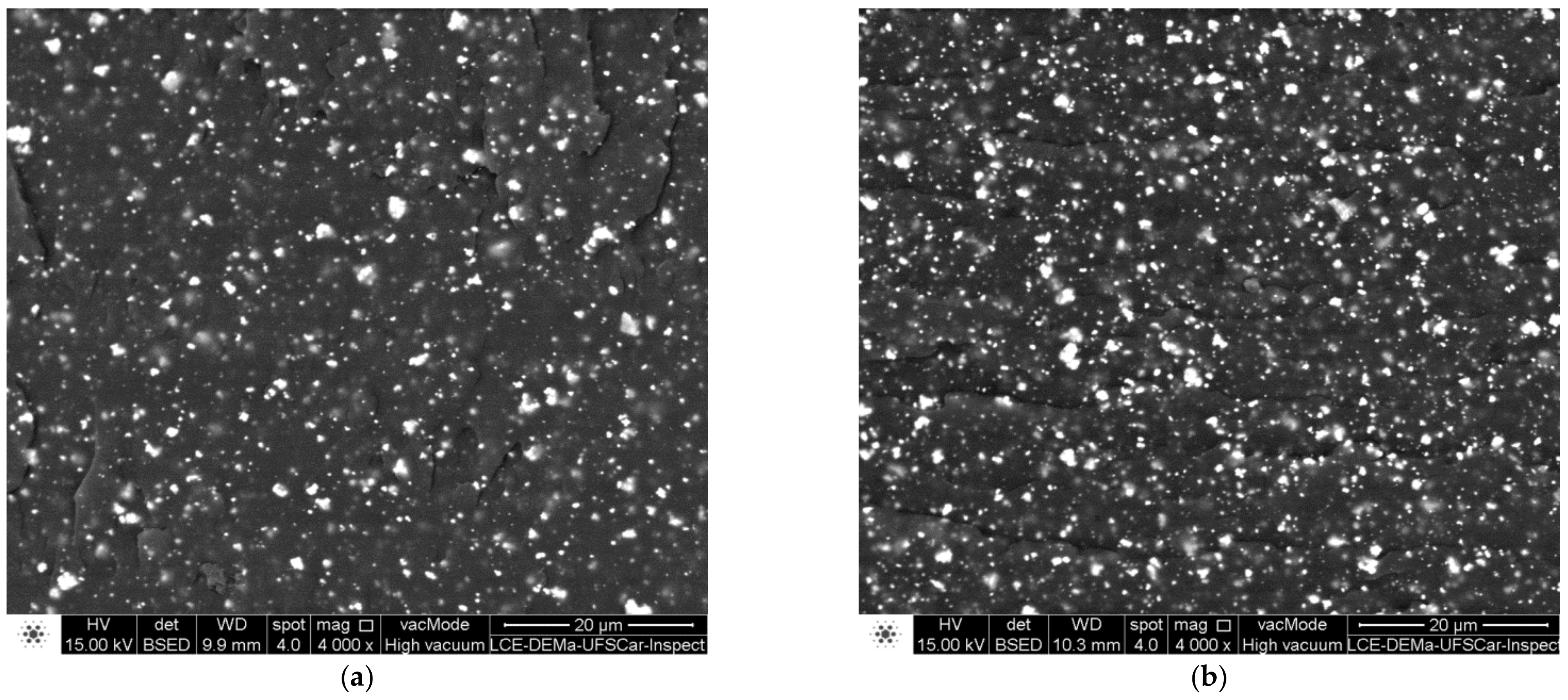
For the extruded composites, the distribution and dispersion of PZT particles in the polymer matrix were analyzed via SEM of the fractured surfaces (
Figure 6), which were obtained by fracturing of the material under cryogenic temperature.
The best results for distribution and dispersion were observed for screw rotation speed of the extruder, 300–350 RPM, when the PZT volume fractions were equal to 3 and 5%. In
Figure 6, there are SEM images for SNaPZT3 and SNaPZT5 that were obtained using the back-scattered electrons (BSE) mode to eliminate the matrix effect to improve the visualization of distribution and dispersion of PZT particles in the extruded material.
Considering that the signal obtained by BSE is generated via interactions between the primary beam (incident electron beams in the sample), and the electrons present in the regions inside the analyzed material, the images obtained using the BSE mode provide different information. This information depends of the contrast in terms of the topographic image of the region, as well as of the composition in terms of the atomic number of elements in the region [
27]. Therefore, the distribution and dispersion of PZT particles in the matrix were better analyzed via SEM by using the BSE mode. Additionally, the images in
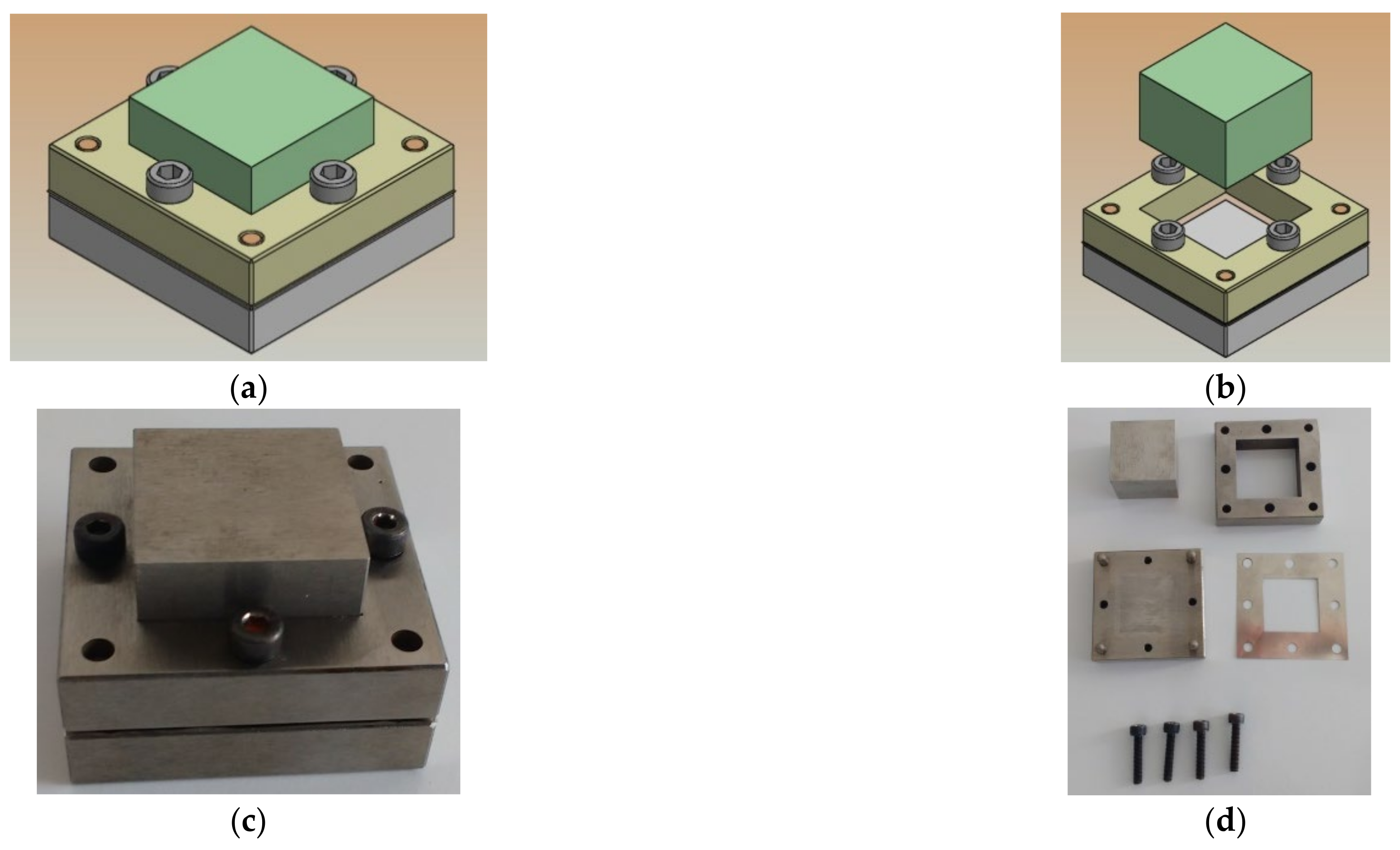
Figure 6 showed that the distribution and dispersion of PZT particles in the extruded material can be considered adequate, generating a highly homogeneous composite, which will be compressed by using the mold (
Figure 2) and a hot press. In other words, this can demonstrate that the methodology for obtaining flexible composite films is successful, showing high potential for obtaining damage sensors with good quality in terms of dispersion of PZT particles.
3.4. Characterization of Flexible Composite Films
3.4.1. SEM Results
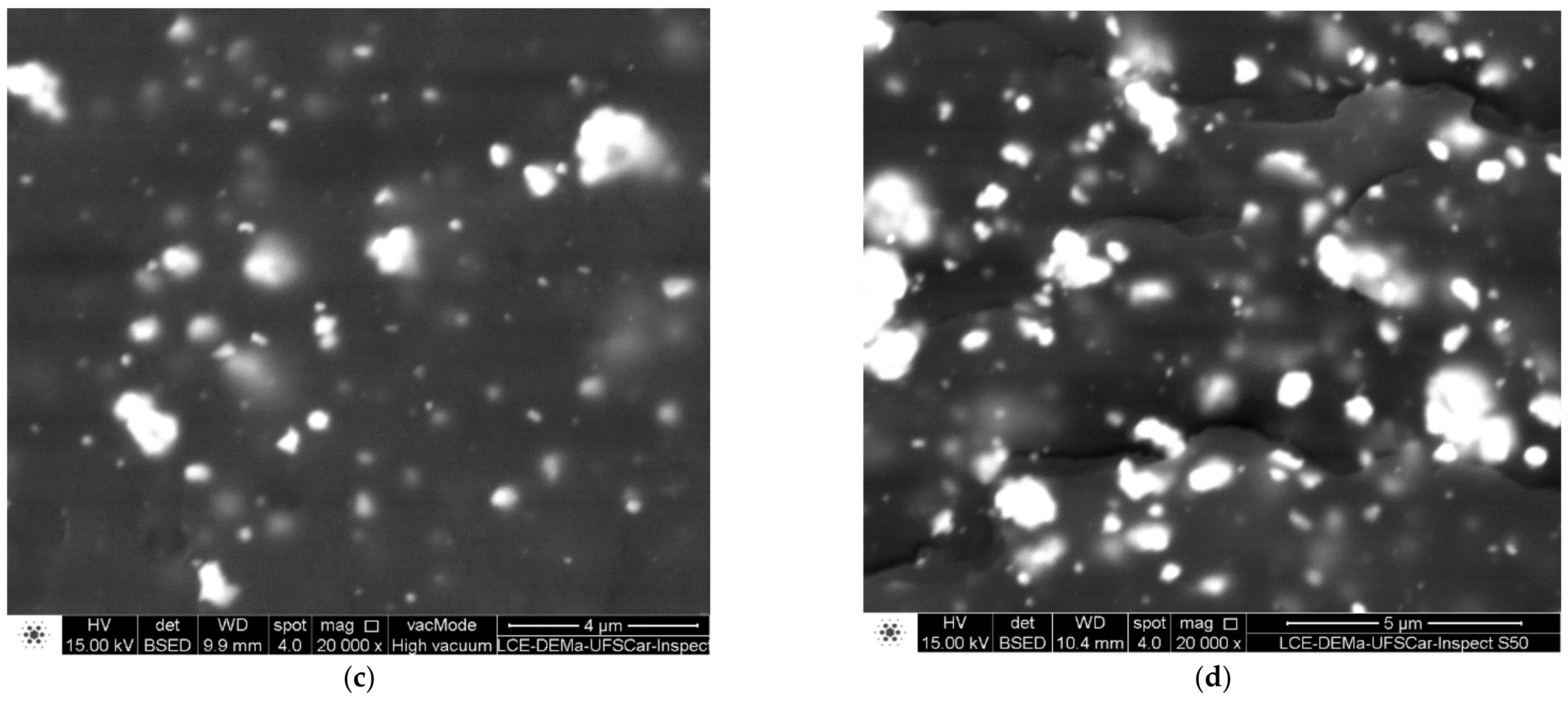
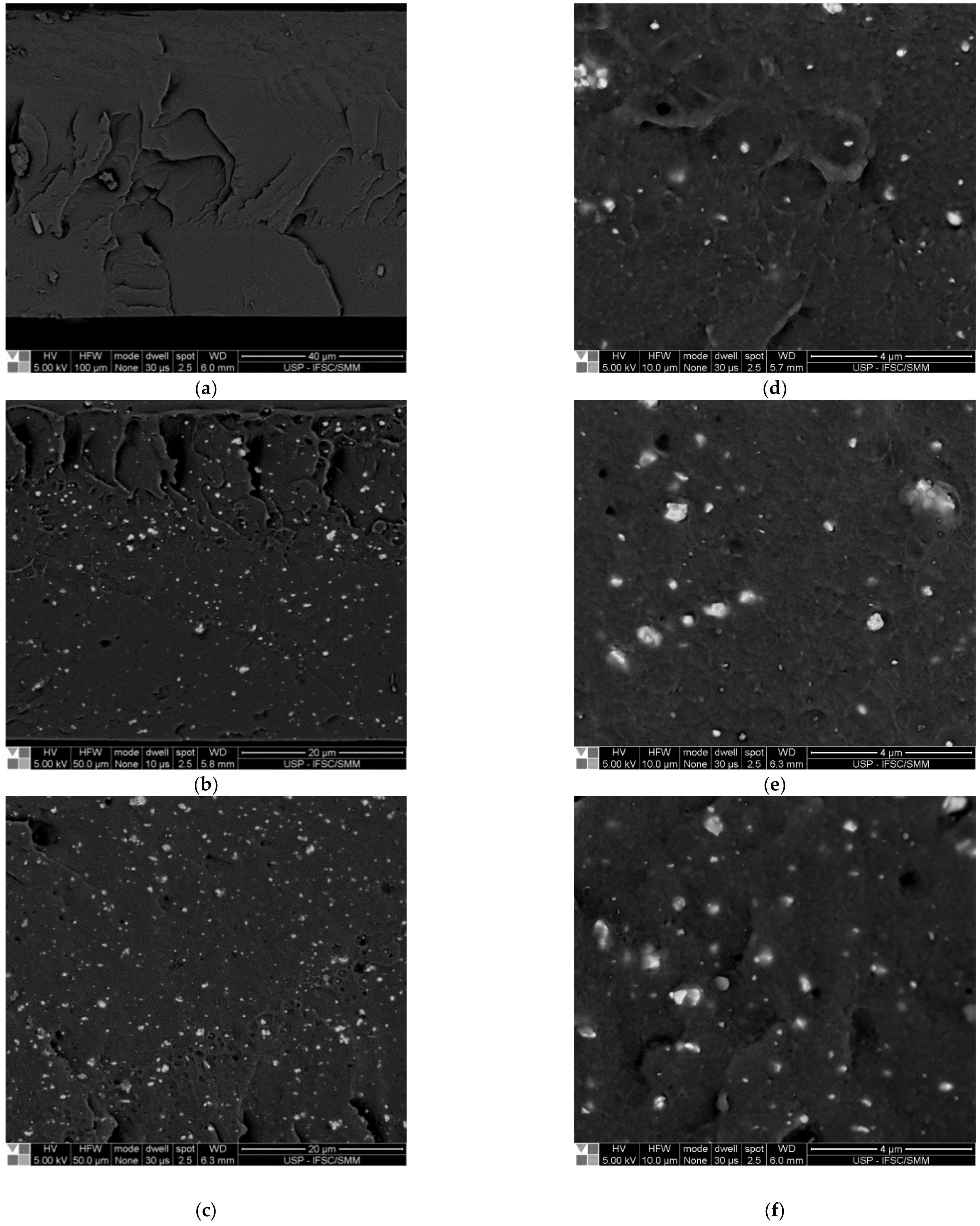
The distribution and dispersion of PZT particles in the flexible films were analyzed after hot compression mold processing via SEM of the fractured surface, as shown in
Figure 7.
In
Figure 7a, there is an image of the pure polymer film SNa0, which can be compared to the images of the flexible composite film with 3% (
Figure 7b,d), 5% (
Figure 7c,e) and 7% (
Figure 7f) of PZT particles volume fraction. The BSE mode was also used during the analysis to verify the distribution and dispersion of particles in the inner regions of the polymer matrix.
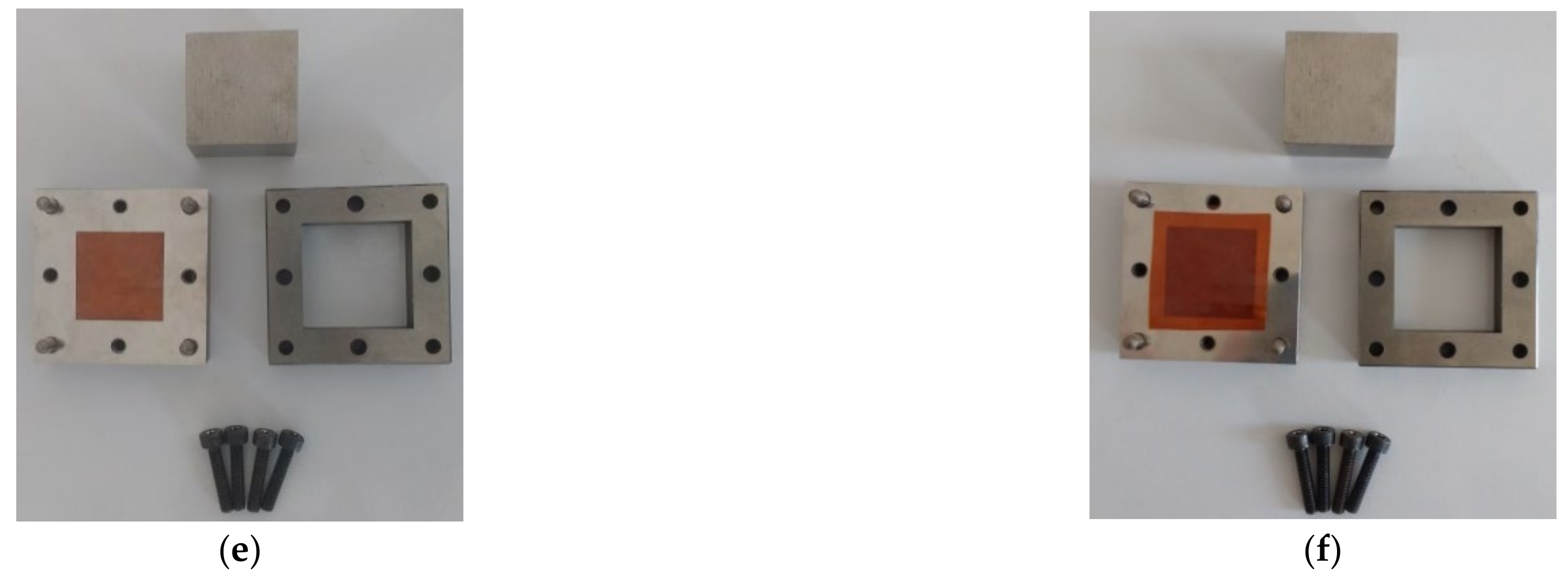
Considering that the observed fractured surfaces of the flexible films were along the thickness, the measurements of the thickness of flexible films provided a value equal to 75.0 ± 11.6 µm using a digital Elcometer
® (Manchester, UK), as shown in
Figure 3b. Additionally, in the SEM images, not only individual PZT particles but also clusters can be verified. For the individual PZT particles, average dimensions lower than 0.10 μm, and for clusters, average values lower than 0.25 μm were observed. Thus, it can be concluded that the dimensions of individual particles and clusters are compatible with the thickness of the flexible films, showing a good distribution and dispersion. Again, this can testify that the methodology for obtaining flexible composite films is successful, showing high potential for obtaining damage sensors with good quality in terms of dispersion of PZT particles.
3.4.2. XRD Results
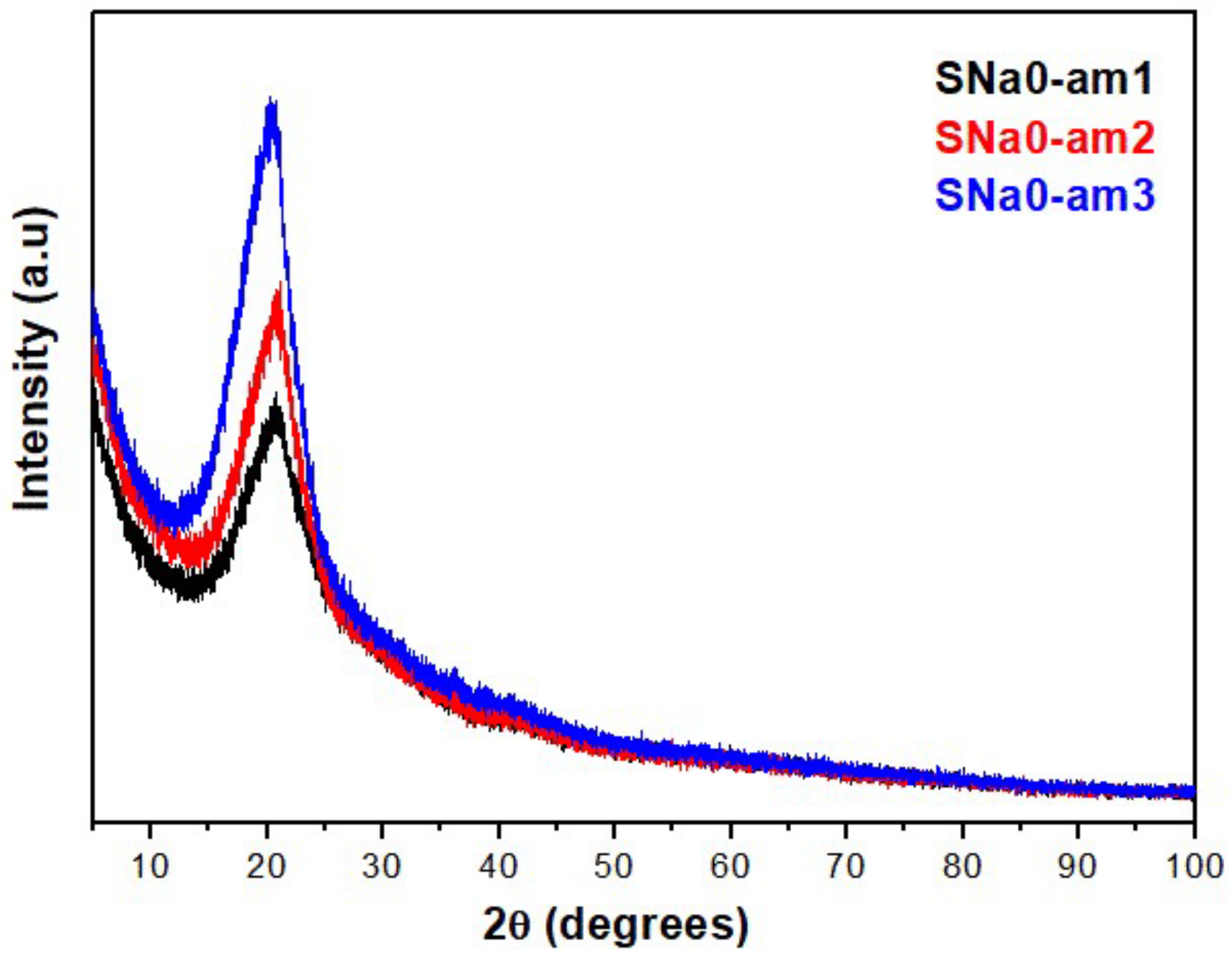
Figure 8 shows the patterns of diffraction via XRD for pure polymer films (SNa0) and flexible composite films (SNaPZT#). In
Figure 8, there are results for three different regions from the same sample of the SNa0 film. In fact, an attempt was made to verify the relevant differences between the patterns of diffraction of a pure polymer film obtained by extrusion and hot compression molding processes. In
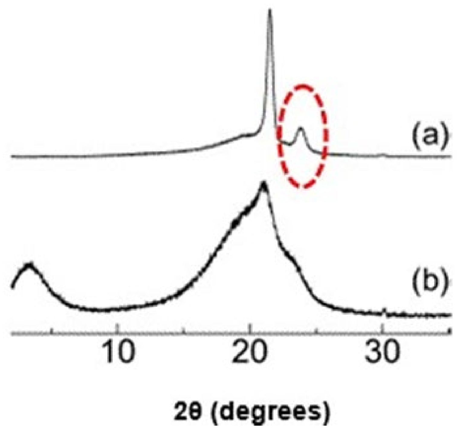
Figure 8, in the region of 2θ equal to 23°, the absence of one of the typical peaks of orthorhombic crystals of polyethylene regarding the plane (200) was observed. These results are in agreement with the literature [
28,
29], as shown in
Figure 9.
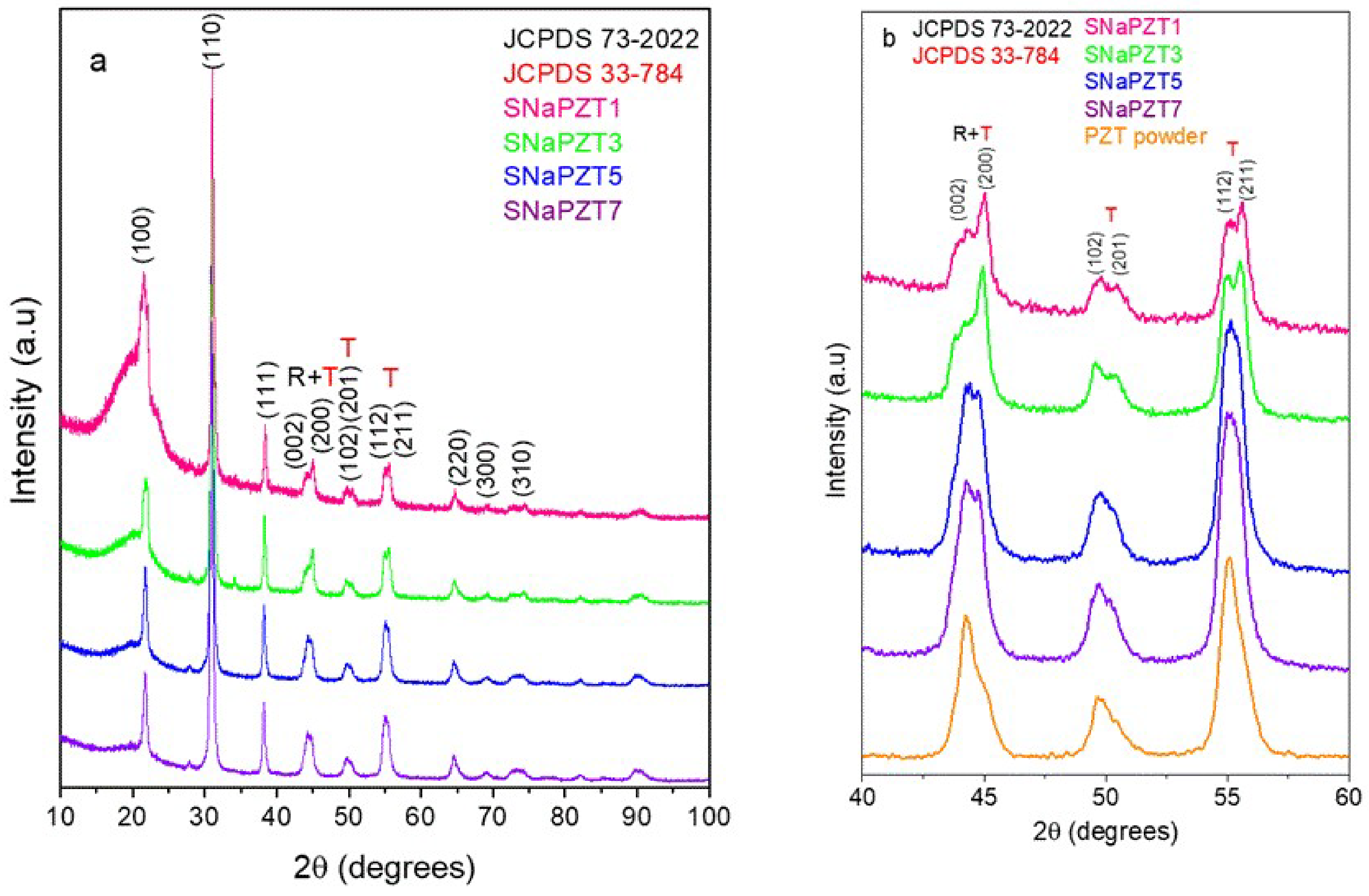
According to
Figure 10, it is possible to note that the presence of the polymeric matrix did not affect the peaks related to the PZT particles (
Figure 10a). The XRD results also showed the permanence of peaks of diffraction of PZT particles related to the rhombohedral phase (200) and tetragonal phase (002) and (200) in the same region of 2θ (between 42° and 47°), confirming that they are in the region of morphotropic limit of the phase transition [
22,
25]. In addition, it was evident that the split peaks regarding the tetragonal phase of PZT (in the region of 2θ between 40° and 60°) were more evident for the composites than the pure PZT particles (
Figure 10b).
Previous publications concluded that the ionic interactions present in the multiplets and, consequently, in ionic aggregates, increase the “internal” viscosity of the ionomer, reducing the mobility of the ethylene segments in the chain and avoiding the exclusion of groups related to the methacrylic acid (MAA) and to their derived carboxylate ions (MAA
−Na
+) present in lamellae [
28,
29,
30]. This explains the absence of the diffraction peak related to plane (200) at 23°, which is typical for the orthorhombic crystals of polyethylene, as shown in
Figure 9a.
Goméz, Gasparini and Canevarolo [
31] studied a new morphologic model for explaining the semicrystalline ionomer EMAA
−Na
+ by using thermal-optic techniques. They proposed a schema with the presence of groups related to the methacrylic acid (MAA) and their derived carboxylate ions (MAA
−Na
+) in the ionomer, before and after thermal aging treatments under dry and humid atmosphere. They observed that the primary crystals of polyethylene were formed by lamellae along their ethylenic segments where there are non-crystallized comonomers of MAA e MAA
−Na
+. Those observations can be applied in the present investigation using XRD because the peak of diffraction related to the plane (200) at 23°, which is typical in the orthorhombic crystals of polyethylene, was not observed in the SNa0 film (
Figure 8). This occurs due to the presence of non-crystallized comonomers (MAA e MAA
−Na
+) in the ethylenic segments that form the lamellae of the ionomer, Surlyn
® 8940.
The presence of two phases (rhombohedral and tetragonal) in the samples increases the possibility of alignment of ferroelectric domains during polarization under the application of a strong electrical field (DC—direct current) [
22] and, consequently, better dielectric and piezoelectric properties [
32].
3.4.3. DMA Results
By using DMA, it was possible to analyze the thermomechanical properties of the flexible pure polymer film (SNa0) and flexible composite films (SNaPZT#), as well as the influence of the PZT particles volume fraction on the thermomechanical responses.
The dimensions of the DMA specimens are described in
Section 2.4.3 (Dynamic Mechanical Analysis Conditions).
According to Canevarolo Jr. [
33], there are different methods for evaluating the temperature of the same transition, such as: (1) the temperature at the beginning of the fall down or at the extrapolated beginning (T
E′onset) of the storage modulus curve (E′); (2) the temperature at the beginning or at the peak (T
E″peak) of the loss modulus curve (E″); (3) the temperature at the beginning or at the peak of the damping curve (tan δ); (4) the extrapolated temperature of the change at baseline (in the format of “S”) in the differential scanning calorimetry (DSC) curve.
Table 2 shows the results for glass transition temperatures of SNa0 and SNaPZT# films via DMA, which were determined with two different methods (1 and 2). In fact, the glass transitions occur due to the different morphological transformations, devitrification of the regions rich in ions and fusion of secondary crystals, which take place simultaneously, promoting gradients of glass transition temperatures in different regions of the ionic clusters, according to the thorough investigation carried out by Miwa, Kondo and Kutsumizu [
29].
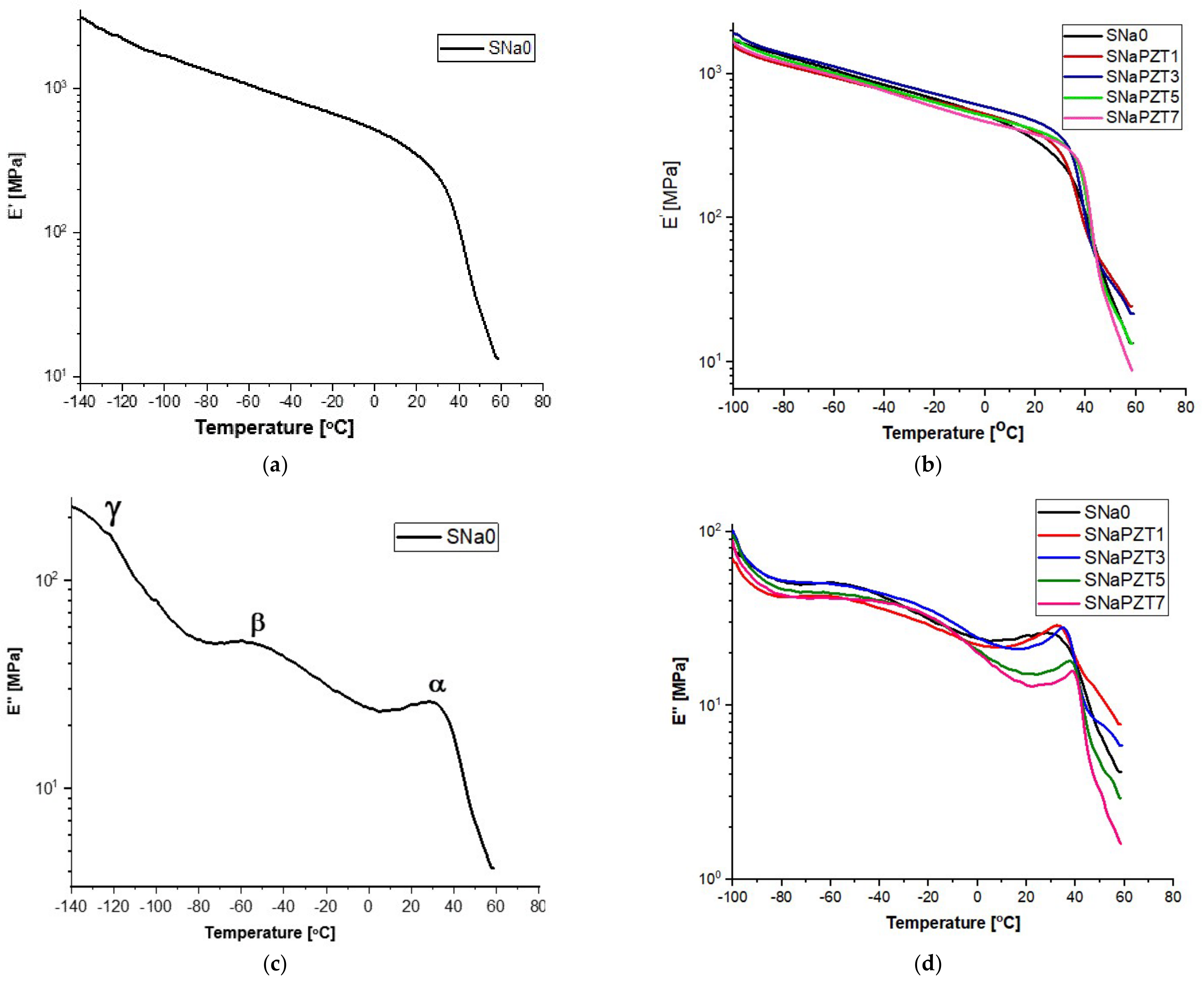
In
Figure 11, it is possible to observe the DMA results for the SNa0 and SNaPZT# films. The storage modulus (E′) of SNa0 (from −140 °C) and SNaPZT# (−100 °C) from the films is shown in
Figure 11a,b, respectively. The loss modulus (E″) of SNa0 (from −140 °C) is shown in
Figure 11c. Different curves of the loss modulus (E″) of SNaPZT# (from −100 °C) are shown in
Figure 11d, highlighting the α, β and γ relaxations.
Comparing the curves in
Figure 11, it was observed that the addition of PZT particles produced only small changes in the viscoelastic relaxations of films. According to the literature [
34,
35,
36,
37,
38], for ionomers of EMAA neutralized by ions Na
+, the γ relaxation is related to the molecular movements of short segments of the polymer chain in the amorphous phase. α and β relaxations are related to the neutralization by ions Na
+ and indicate that there is a separation of phases between the ionic aggregated and the polymer phase of the hydrocarbon matrix, with the consequent formation of ionic clusters. α relaxation is frequently assigned to the glass transition due to the microbrownian molecular movements of the main chain segments close to the region of ionic clusters. Longworth and Vaughan [
28] already reported a drop in the storage modulus (E′) and a peak in the loss modulus (E″) in the temperature range of α relaxation in the ionomer that was only dry annealed at room temperature. Those changes were related to the dependence between the relaxation of the ethylene chain segments and the ionic interactions, being significantly present in these temperature ranges. Wakabayashi and Register [
35,
39] interpreted the α relaxation as a consequence of the melting of secondary crystals and the creation of breaks (points of failure) in the rigid pathway, causing the acceleration of reduction in the storage modulus (E′).
β relaxation is related to the movement of long segments of the amorphous region of the branched polyethylene phase and to the rotation around the linkages of lateral groups to the main chain. Therefore, in the present investigation, α and β relaxations were associated with the individual molecular movements that occur in the ionic clusters (α relaxation) and in the polyethylene chain (β relaxation). Deschanel et al. [
36] also mentioned that β relaxation can be related to the response of glass transition of the copolymer non-neutralized in the amorphous phase, which was considered as belonging to the restricted mobility region.
The peaks in the curves of the loss modulus (E″) (
Figure 11c,d), between 30 and 45 °C (α relaxation), are related to the molecular relaxations due to the transition order–disorder of the ionic content or due to the glass transition in the long segments of the polymer chains in the regions of ionic clusters, as shown by Kalista Jr., Pflugc and Varley [
40] and Miwa, Kondo and Kutsumizu [
29]. With the increase in the volume fraction of PZT, there was an increase in the temperature at which α relaxation (α transition peak) occurs and the magnitude of E″ increases (
Figure 11d), which is an indication of the reduction in molecular mobility with the addition of PZT.
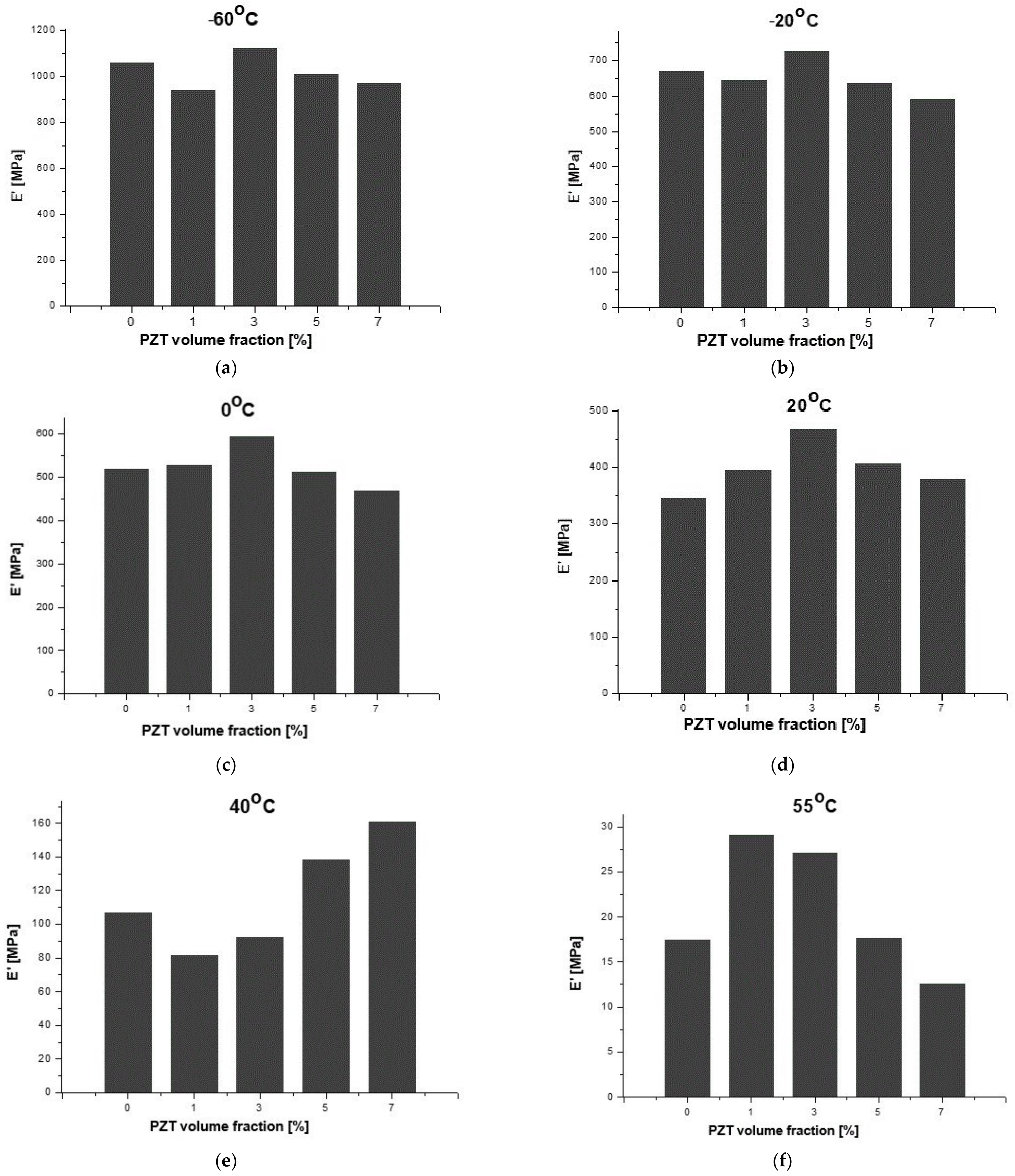
Considering the results for the SNa0 film as a reference in the present investigations, in
Table 3, it is possible to observe the percentage variations of storage modulus (E′) in terms of temperature for different PZT volume fractions when compared to the respective results for the SNa0 film at the same temperature. It should be noted that the results shown in
Table 3 and
Figure 12 are only qualitative and only indicate trends. It is well known, mainly in the aeronautical field, that it is necessary to continue the work with quantitative analysis of the results, using statistical methodologies of the data obtained from tests of a greater number of replicates.
Regarding the aeronautical applications for the sensors and observing
Figure 12, from −60 °C to 20 °C, which consists of a critical interval of temperature for the evaluation of applications of the SNaPZT# composite flexible films for monitoring damage at low temperatures in an aircraft in service, it was verified that SNaPZT3 showed a tendency to increase this property. This suggests that there is better interaction between the matrix and the particles when the PZT volume fraction is equal to 3%. At a temperature of 40 °C (
Table 3 and
Figure 12e), within the range of temperatures in which an α relaxation occurs, the composite films show a tendency of opposite responses in terms of percentage variation of the storage modulus (ΔE′) when compared to the results under other temperatures shown in
Table 3 and in
Figure 12a–d,f (i.e., under temperatures of −60, −20, 0, 20 and 55 °C). A greater reduction in the storage modulus (E′) was observed for the composites SNaPZT1 and SNaPZT3, around 24.0% and 13.0%, respectively, which indicates a smaller interference of these PZT volume fractions (1 and 3%) in the relaxation of ethylene chain segments and, therefore, in the microbrownian molecular movements of the main chain segments close to the region of ionic clusters. Even so, SNaPZT3 remains very attractive for monitoring damage in aircraft at low temperatures (between −60 and 30 °C). The same previous considerations are highlighted regarding the need to carry out quantitative investigations. Therefore statistical analysis of the dispersion of values obtained after testing of a greater number of replicates can be perfomed.
Investigations via solid-state Nuclear Magnetic Resonance (NMR), using the
13C cross-polarization magic angle spinning (
13C CPMAS) technique, were carried out by Costa et al. [
41] and showed that, for flexible composite films with 3% of PZT volume fraction, the signal related to the segments of -CH
2- in the amorphous regions of the polymer chain practically did not vary. However, for flexible composite films with 7% of PZT volume fraction, the intensification of the signal in the amorphous segments was verified, which is coherent with the DMA results. This occurs because more intensive perturbations were observed in the segments of the polymer chain, as shown in
Figure 11d. At a temperature of 20 °C, the SNaPZT3 film showed the highest percentage variation of the storage modulus E′ (in
Table 3) compared to the other films (35.5%).
The same authors also used the
13C dipolar chemical shift correlation (
13C DIPSHIFT) technique, at 83 °C [
41]. Those studies tried to identify the molecular origin of dynamic transitions for the flexible composite films. It was verified that the amorphous portion of the polymer chain for the SNaPZT7 films showed the highest reduction in molecular mobility due to the higher PZT volume fraction. Moreover, Costa et al. [
41] concluded that the PZT volume fraction in the flexible composite film should be lower than 3% because, for higher values, the molecular dynamic of the polymer would suffer significant reductions.
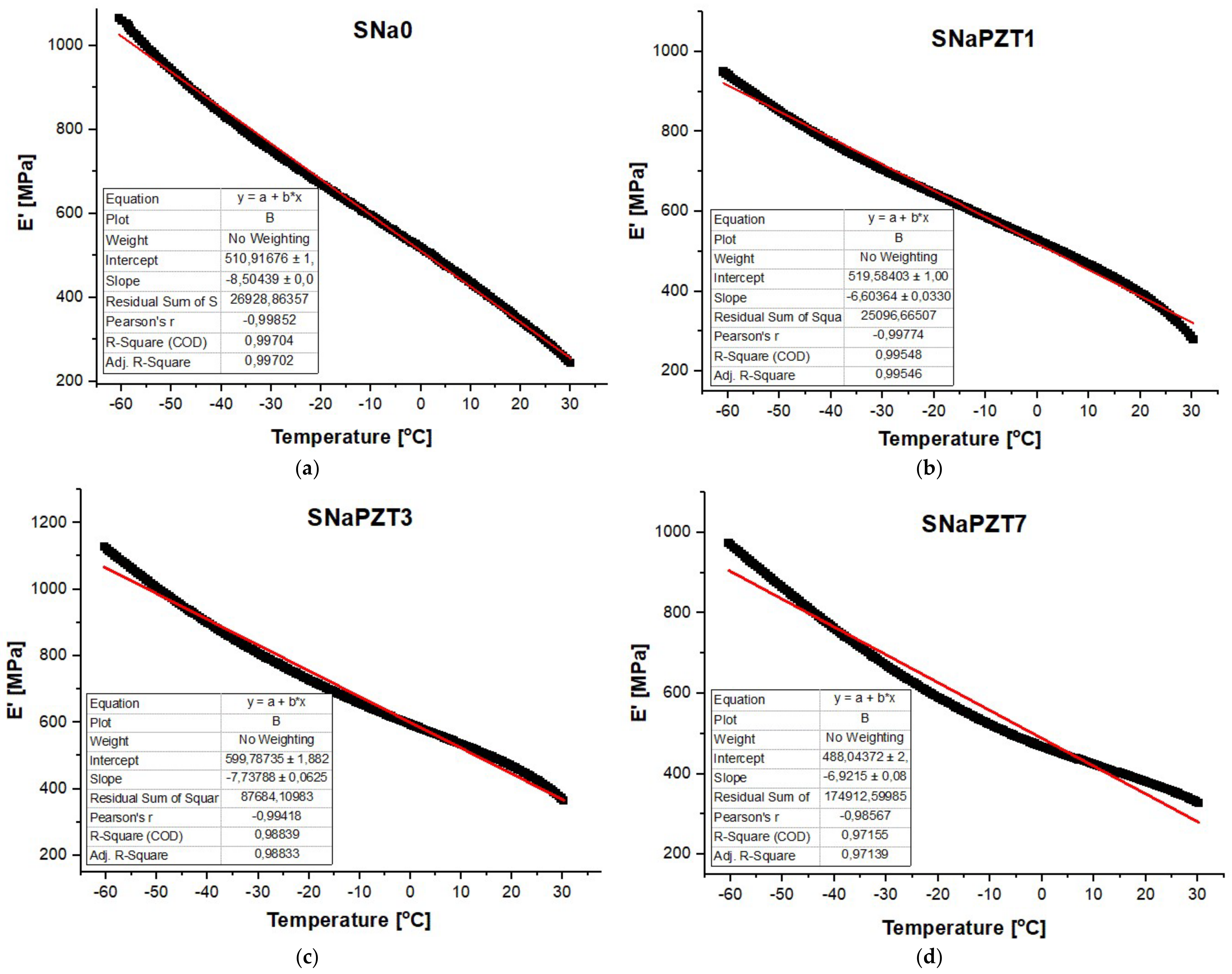
Figure 13 shows that there is a linear behavior of the storage modulus (E′) in terms of temperature for the SNa0 and SNaPZT# films. The interpolation results for 0, 1, 3 and 7% of PZT volume fractions were observed. The result for 5% is not available, but it is similar to the others. This kind of behavior is very interesting for the development of theoretical models, which aid in predicting the thermo-mechanical behavior of the sensors when applied in the aeronautical structures, considering the investigated range of temperature. This is another contribution for the real application of the sensors in the aeronautical field, where the structure can be from −50 °C to 30 °C.
3.5. Tensile Testing Results
The dimensions of the films for tensile testing did not follow any specification given by technical standards due to the limitations on manufacturing the flexible films in the present study. However, during all tests, it was guaranteed that the sample was only under uniaxial tensile loading. Moreover, end tabs were used to avoid the failure of the samples close to the clamps. For each type of film (SNa0 and SNaPZT#), five rectangular samples with 25.00 mm length, 0.06 mm thichness and 10.00 mm width were tested.
After the tests, the engineering stress and strain were calculated to perform a comparison of the different films in terms of the PZT particle volume fractions.
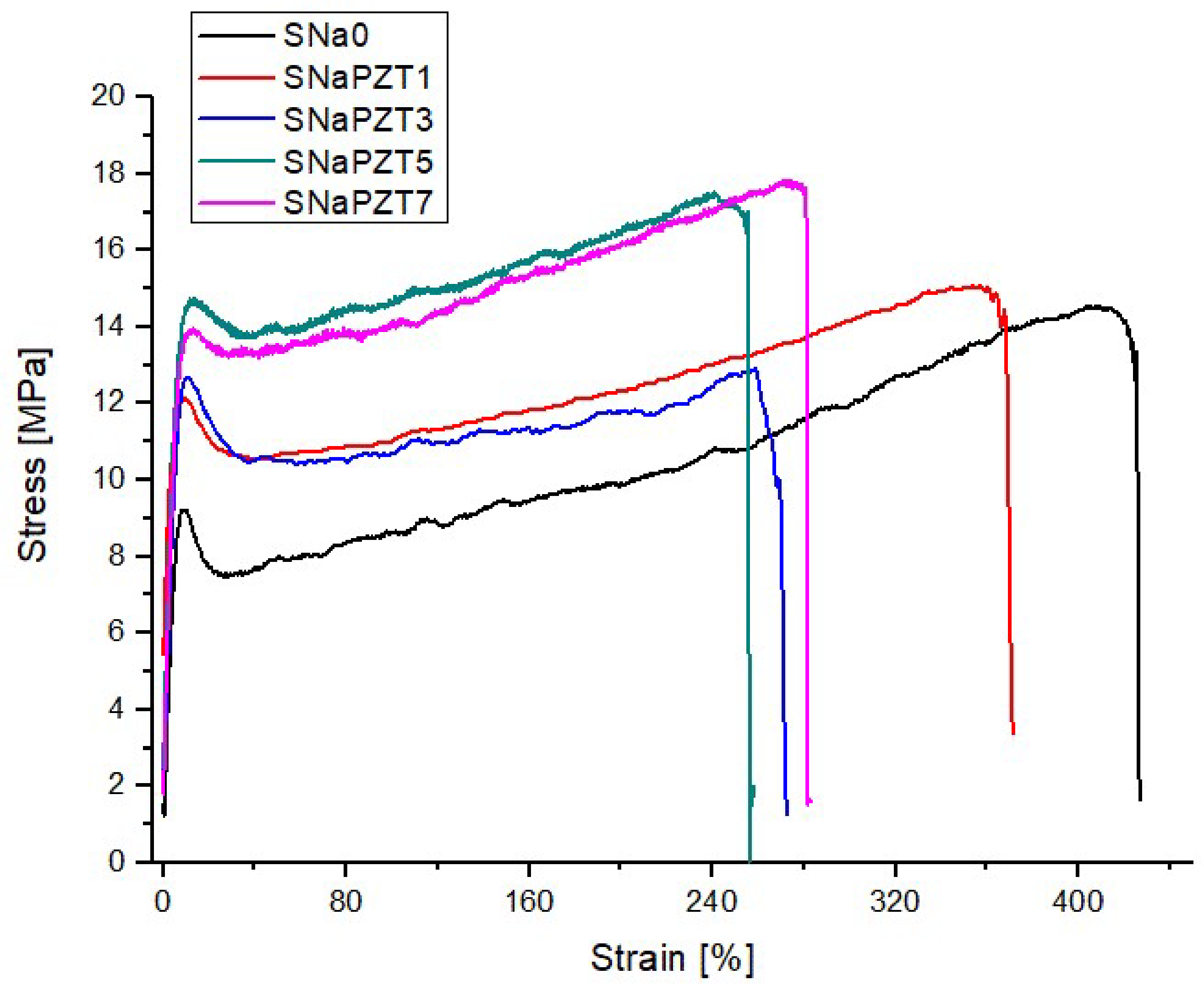
Figure 14 shows the typical tensile stress–strain engineering curves obtained for the SNa0 and SNaPZT# films. In
Table 4, it is possible to observe the mechanical properties of the films obtained from the stress–strain curves. As expected [
14], there was a relevant reduction in the maximum strain values with the increment of the PZT volume fractions. Despite of the addition of PZT particles, the films were still ductile, which is a very important characteristic for damage sensors.
As expected, the addition of PZT particles reduced the molecular mobility as discussed previously in the DMA results and in the investigations of Costa et al. [
41]. This is reflected in the increment of the Young modulus (E) for all SNaPZT# films (
Table 4).
The rupture stress value provided by DuPont for SNa0 (pure polymer), 33 MPa, is higher than twice the average value obtained in the present work, 15.31 MPa. It is important to note that the characterization of the material carried out by DuPont followed the dimensions of samples specified by technical standards, with much larger values.
Regarding the yield stress results, Deschanel et al. [
36] and Scogna and Register [
37] showed information and discussion about the yield stress for the copolymer EMAA. Those authors pointed out that the value of yield stress can be related to a combination of different mechanisms, such as: (a) material strength due to the yield of rigid domains (crystalline regions); (b) material strength due to intermolecular interactions in the amorphous phase (this is very important if T < T
g or T≈T
g, and if the test speed is high); (c) material strength due to the strain and orientation of the molecular net in the amorphous phase (net of chains linked or not to crystalline and amorphous domains). The investigations by Eisenberg et al. [
2] about ionomers similar to EMAA had confirmed that there is a high difficulty in relaxation of the amorphous polymer segments in the vicinities (around) of ionic aggregates. On the other hand, under very low strain rate, the yield stress values are higher. In other words, lower values of yield stress can be related to the plasticity response of the polyethylene crystals and the incomplete relaxation of the amorphous segments of the polymer chains in the regions of restricted mobility. In
Table 4, it is verified that the yield stress increases with the increment of PZT volume fractions, although significant increments are not observed. Therefore, the obtained yield stress values indicate that the presence of PZT particles created more difficulties for the relaxation of the amorphous segments of polyethylene chains in the regions of restricted mobility, as confirmed by NMR results published by Costa et al. [
41] and by using the results of the DMA.
3.6. Comparative Data with Traditional Materials
Composites made of ferroelectric polymers (e.g., PVDF) with ceramics particles (e.g., PZT) are widely studied for application in hydrophones, generation of images in the biomedical area with ultrasound and applications in non-destructive testing [
42].
Regarding PVDF, in accordance with the theories of polymer physics, there are no studies in the literature, which confirm the presence of necessary and sufficient secondary interactions to establish a supramolecular structure. Consequently, PVDF cannot be considered as a material capable of self-healing/healing damage at the early stages.
Some properties and characteristics of the Surlyn
®-type thermoplastic matrices (such as the ionomer EMAANa or SNa0) and the PVDF matrix were compared in
Table 5. The density of the Surlyn
® 8940 matrix (EMAANa type), equal to 950 kg/m
3, which was determined by the manufacturer DuPont Packaging & Industrial Polymers [
43], is lower than the PVDF matrix, as highlighted in [
19], which is equal to 1900 kg/m
3, and in [
44], it provides values between 1740 and 2000 kg/m
3. Dynamic-mechanical thermal analysis (DMTA) studies showed wide temperature intervals referring to the different relaxations present in the ionomers (β and α relaxations), for example, for the SNa0 matrix, between −60 and 50 °C [
35]. Considering the transition temperature gradients referring to the segments of polymeric chains present inside and outside the regions of restricted mobility of the SNa0 ionomer matrices [
29], different possibilities of application of these materials can be explored. Although the EMAANa-type matrix has a lower melting temperature, when compared to the melting temperature of PVDF, the self-healing capacity gives an additional advantage for the use of the former (EMAANa) in terms of recyclability. In addition, the Young modulus of SNa0 is more than four times higher when compared to PVDF (
Table 5), and it is almost six times higher for flexible composite films.
Therefore, there are some differences between PVDF and the Surlyn®/PZT ionomer composites (flexible composite films) studied in this work, such as: (a) in PVDF, there is no self-healing with initial damage; (b) the densities of PVDF are much higher than the Surlyn®/PZT composites. In fact, the density values of PVDF exceed those found in composites for aeronautical applications, for example, those based on carbon fiber/epoxy resin, which have densities around 1300 kg/m3.
Considering the aspects pointed above, it is shown that the flexible composite films present high potential to be applied in composite structures.


 ,
, 


