1. Introduction
Compound drop manipulation is of fundamental and practical interest in diverse fields, including drug delivery [
1], combustion [
2], 3D printing [
3], and self-cleaning [
4,
5,
6]. The impingement of the compound drop, such as Janus, core–shell, and particle-laden configurations, can bring more opportunities for applications owing to their particularities and numerous combinations of complex drops and complex surfaces [
7,
8]. Extensive studies have been carried out to investigate the mechanisms of the drop bouncing and the methods for bouncing promotion or suppression [
9,
10]. The drop dynamics can be governed by the theoretical Rayleigh limit given by
where
ρ,
D0, and
σ are the density of the liquid, equilibrium diameter, and interfacial tension, respectively [
11,
12]. There are relevant dimensionless numbers:
where
U0 is the impact velocity and
μ is the viscosity of the liquid. Here, Weber number (
We) indicates the inertia relative to the surface forces, and Ohnesorge number (
Oh) represents the viscous relative to the inertial and surface forces.
Recently, Yu et al. characterized the spreading and splashing behavior of Janus drop impacts through experiments [
13]. They demonstrated that Janus drops were thermodynamically stable when a high-viscosity fluid was imposed on a low-viscosity fluid. The length of diffusion between the fluids was too small compared to the size of the drop, allowing the drop to act as a two-fluidic system. They also investigated the splashing threshold of the low-viscosity component decreased with an increasing viscosity of the high-viscosity component. Blanken et al. [
14] observed that the water-in-oil emulsion droplet could rebound on the hydrophobic and hydrophilic surfaces owing to a self-lubricating layer between the core drop and the wetting surface. Damak et al. [
15] found an emulsion drop’s transition to bouncing–sticking–bouncing with the help of a formation of the liquid-impregnated surface as the impact velocity increased.
Many researchers have focused on an exploration of the basic physical principle and practical meaning as related to liquid–solid interaction, including drop impact on micro- and nano-structured surfaces [
16,
17,
18,
19,
20,
21,
22,
23,
24,
25,
26,
27,
28]. Bird et al. [
16] studied that superhydrophobic surfaces with macrotextures could decrease the contact time of millimeter-sized water drops by means of center-assisted retraction. The macrotexture played a role in redistributing the mass and momentum. Gauthier et al. [
17] observed a steplike reduction in residence time on repellent wires with increasing impact velocities. They investigated the impact dynamics by varying drop sizes, wire sizes, and impact velocities. Besides the head-on impact on macrotexture, Han et al. [
18] presented fin–stripe non-wettable surfaces for spatial offset maximization and temporal contact minimization of bouncing drops. Other methods have been developed to functionalize the surfaces and modify the performance: vitrimer thin films for durable hydrophobicity [
19], functionalized copper surfaces [
20], and biphilic surfaces [
21] for enhanced heat transfer.
Meanwhile, several efforts have been made to study viscous drop impact on macrotextured surfaces. Abolghasemibizaki et al. [
22] demonstrated steplike reduction in the residence time for viscous drop impact on non-wettable surfaces with a single wire. They also found that the residence time was independent of impact velocity for the inertial-capillary regime, whereas it increased with impact velocity for the viscous-capillary regime. Raiyan et al. [
23] studied the role of viscosity in the impact dynamics on the superamphiphobic surface with macrotextures for varying impact velocities. Our group found that the initial shape of the impinging drop could alter the impact behavior and shorten both the bounce height and residence time significantly when elliptical footprint drops collided on heated [
24], flat non-wettable [
25], and ridged non-wettable surfaces [
26,
27]. The role of viscosity of impinging drops in bouncing dynamics was studied numerically by investigating the residence time on single-ridge surfaces [
27]. Most recently, our group demonstrated the possibility of the separation of the low-viscosity component from the high-viscosity component on macroridge structures by reducing the residence time [
28]. The previous study predicted the bounce and separation behavior for various Weber numbers, viscosity ratios, and initial inclined angles with respect to the ridgeline. However, to further understand physical mechanisms in Janus drop impact on macrotextured surfaces and find strategies in practical terms, fundamentals of how the dynamics of the Janus drop are affected by the sizes of drop and ridge and viscosity ratio should be provided.
In the study, we investigated the asymmetric bounce and separation of impinging Janus drops on non-wettable surfaces decorated with a macroridge to explore the effect of the drop size, viscosity ratio, and ridge size on the dynamics. By attaching a high-viscosity component into a low-viscosity component, Janus drops consisted of two fluidic parts: one was a W-part named after water; the other was a G-part named after glycerin/water mixture, as shown in
Figure 1. We assumed the impact configuration in which the interface between the two fluidic parts was normal to the solid surface. Through numerical simulations, we determined the threshold Weber number of the W-part (
Wec,w), above which separation occurred, and the residence time of the W-part (
tc,w) by varying drop diameters and viscosity ratios of the Janus drops in the volume of fluid (VOF) method [
29]. The initial bouncing directions of separated drops were investigated as a function of the impact velocity and viscosity ratio. Lastly, we predicted how the separation efficiency was affected by the heights and widths of ridges. The findings can provide strategies to control drop bouncing in applications, such as liquid purification [
30,
31] and additive manufacturing [
32,
33].
2. Numerical Methods
The VOF method was employed to predict the interface of the Janus drops on a macrotextured surface. The VOF algorithm reported by Rider and Kothe [
34] was used to trace the interface. Water (W-part) and glycerin/water mixture (G-part) were used as two phases of Janus drops, surrounded by air at atmospheric pressure and room temperature as a third phase. The local volume fraction
ψi for each phase
i can be represented as
. Numerical schemes were based on previous methods for the prediction of liquid–solid interaction [
25,
35]. The three-dimensional mass and momentum equations were calculated in the domain as follows:
where density and viscosity are represented as
and
, respectively,
κ is the curvature of the interface
,
is the unit vector normal to the interface, and
is the gravitational acceleration. As the simplest model, the continuous interfacial force approximation was employed for the calculation of interfacial tension in the last term of the momentum equation [
36]. The advection of the volume fraction was applied in the model as
. The temporal and spatial derivatives were discretized by utilizing the first-order implicit scheme and convective models reported by Leonard [
37], respectively. We made a rectangular computational domain of 11 × 11 × 6 mm
3 in size and a mesh resolution of at least 55 cells per
D0. We also densified the cells near bottom surfaces self-adaptively to improve the precision of computation. For the velocity and pressure fields, the normalized residuals were set to be smaller than 10
–5. The maximal internal iteration and minimal time step were chosen as 40 per time step and 0.1 μs, respectively.
The basic size of the ridge was controlled to the height of
h/D0 = 0.2 and width of
w/D0 = 0.05. The ridge’s size varied under the ranges of
h/D0 = 0.05 − 0.5 and
w/D0 = 0.025 − 0.4. In the domain, the initial spherical shapes containing W- and G-parts with a certain
D0 were patched near the macroridge.
Table 1 presents the liquid properties for two fluidic parts in a certain weight percentage, measured by [
22]. A static contact angle model was employed to characterize the wettability of the ridge and surface in the current work. The current study set the contact angle of 160° as the wetting condition because of dynamic angles (~160°) for the advancing and receding and too small contact angle hysteresis (<4°), reported by [
22].
Several viscosity ratios between W- and G-parts (
α ≡ μg/
μw) are represented as
α1 −
α4, as shown in
Table 1. The subscripts of physical quantities,
w and
g, indicate the properties of W- and G-parts, respectively. W-parts have the equilibrium diameter
Dw =
D0/2
1/3 derived from volume conservation and impact velocity
U0 = 0.5 − 2.5 m/s. For W-parts, the interplay between the inertial and surface forces is important, and the viscous force is negligible because of
Ohw = 0.003 at
D0 = 2.0 mm. For G-parts, the viscous force can govern the impact dynamics because
Ohg = 0.099 − 4.22 at
D0 = 2.0 mm. The
tc is defined as a residence time on the surface. Ω represents the separated volume relative to the initial volume for W-parts, called as a separation efficiency. The axial momentum
p is calculated from the volume integral of the axial momentum divided by the initial momentum.
To validate the current simulation, we compared the numerical data of maximum spreading diameters (
Dm) with the fitting lines of experimental data obtained from single-phase viscous drop impact on flat surfaces [
22]. We introduced a dimensionless number, called impact number (
P = We/Re4/5) to estimate whether capillarity or viscosity ruled the hydrodynamics. Clanet et al. [
12] suggested the relations of
Dm/D0 ~ We1/4 for
P < 1 and
~ Re1/5 for
P > 1. Afterward, the experimental demonstration presented the numerical coefficient of 0.83 in the relations as follows [
22]:
Our numerical data of water and glycerin/water mixtures (75 and 95 wt.%) agree with Equations (6) and (7), as shown in
Figure 2. When the impact number passes unity, it can be a transition point from capillarity to the viscosity dominance in the drop dynamics.
3. Results and Discussion
Bouncing characteristics of drops on the macroridge structures can depend on the drop size, impact velocity, and viscosity ratio.
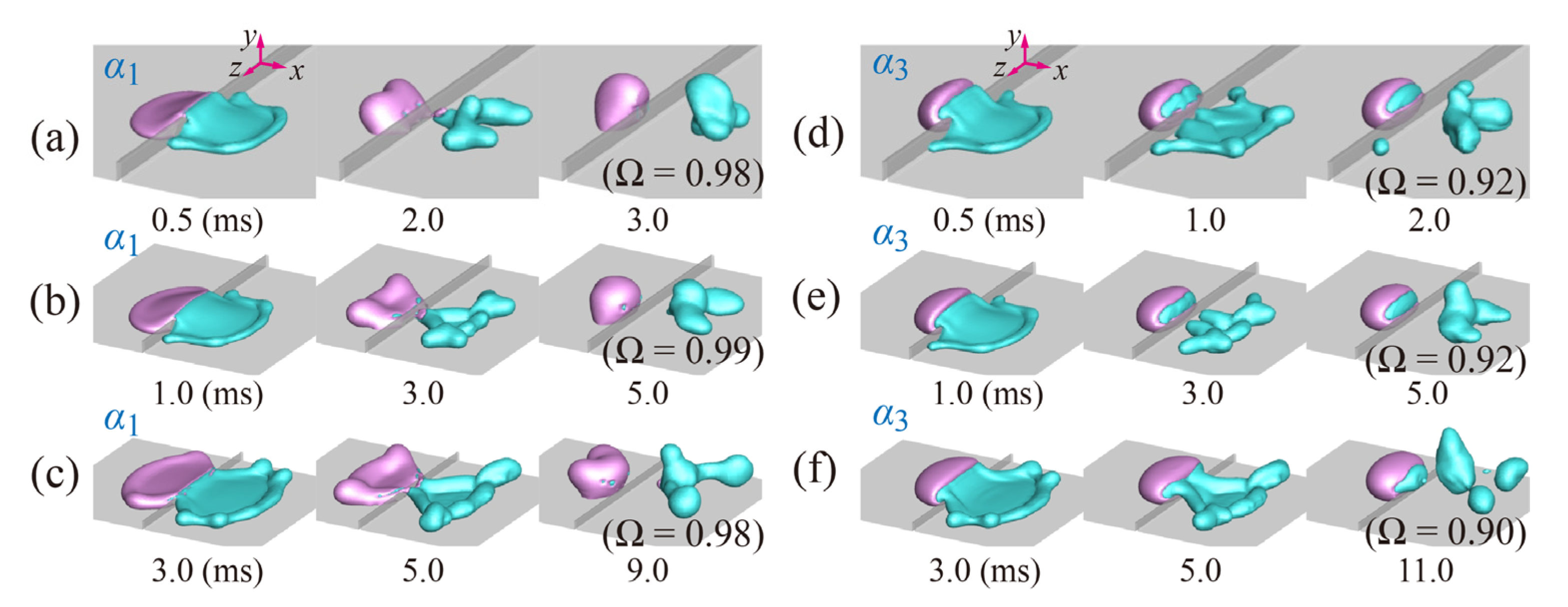
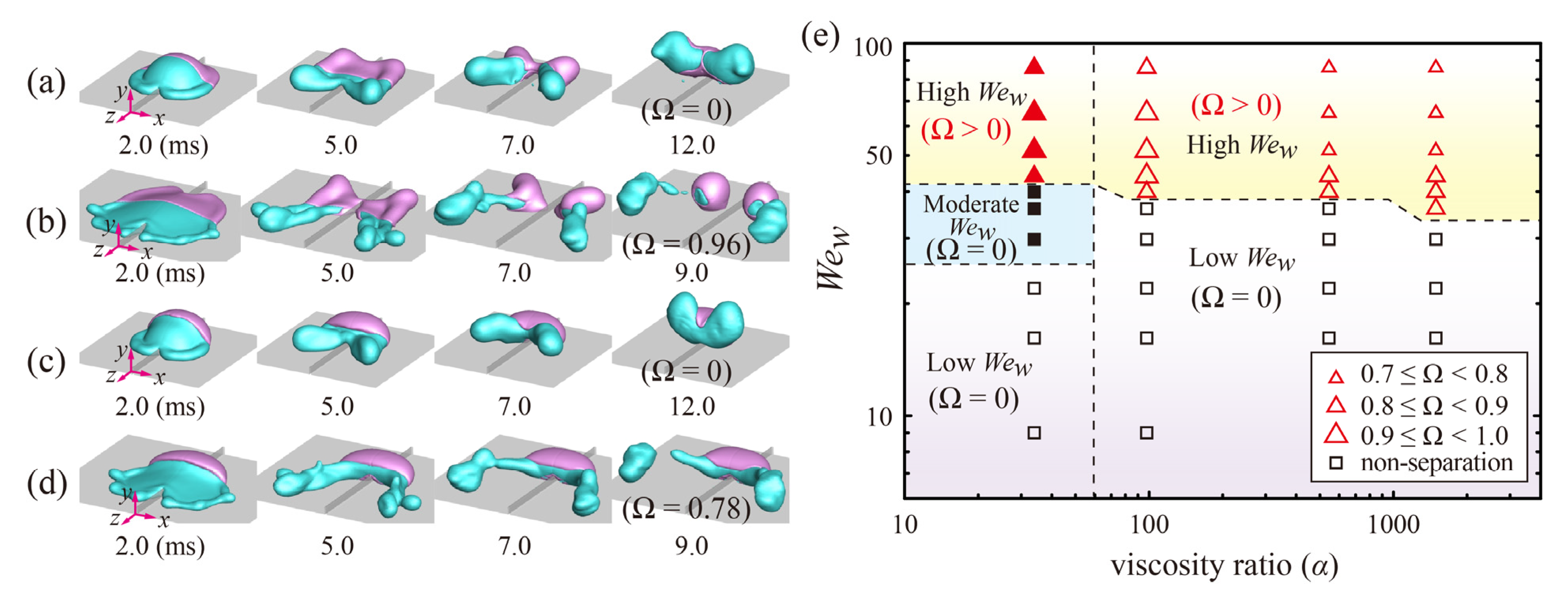
Figure 3a–d show the morphological behavior of the impinging drops under the different impact velocities and viscosity ratios at
D0 = 1.33 mm. In the low-viscosity ratio (
α1), W- and G-parts exhibit large deformations throughout the spreading and retraction, as depicted in
Figure 3a,b. After touching the surface at smaller
Wew, the W-part spreads more widely in the
x-direction than the
z-direction, as shown in
Figure 3a at 1.0 ms. The film of the part shrinks toward the G-part, thereby leading to symmetric division and bounce of the two parts, as illustrated at 6.0 ms. Note that the G-part is redistributed into two symmetric parts only for
α1. For a high
Wew, the film of the W-part is thinner and wider compared to that observed at the smaller
Wew, and thus the newly formed inner rim strongly retracts toward the outer rim along the
x-direction, as seen in
Figure 3b at 2.0 ms. A large portion of the W-part is lifted off from the surface and then separated from the G-part (i.e., Ω = 0.93). Distinct from the dynamics in the low-viscosity ratio, the notable difference is observed between the dynamics of W- and G-parts in the high-viscosity ratio (
α3). The W-part is still attached to the G-part at a low
Wew (
Figure 3c), whereas it is partly split from the G-part at a high
Wew (
Figure 3d). A higher inertia of the W-part allows the drop to be separated from the G-part (i.e., Ω = 0.81), compared to the dynamics in the low
Wew.
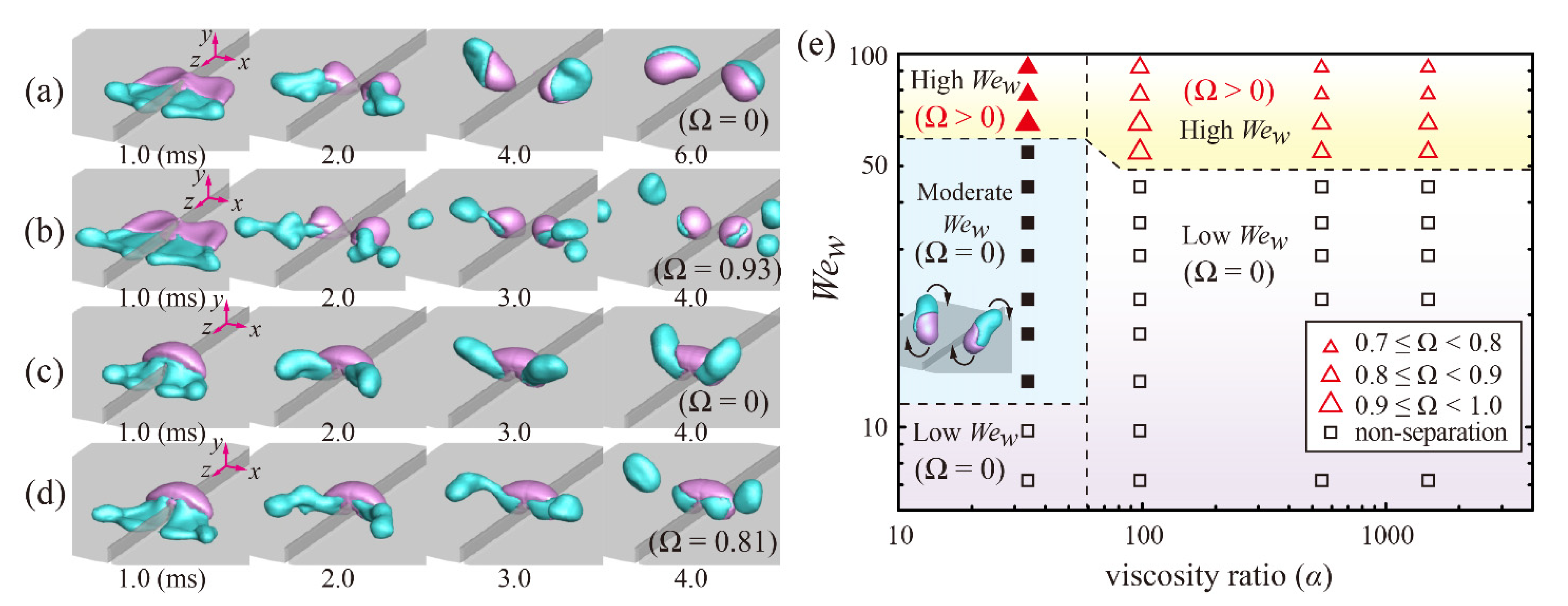
For a quantitative understanding, the bounce and separation behavior can be further investigated by introducing a regime map as a function of
Wew and
α, as illustrated in
Figure 3e. Triangle and square symbols in the map indicate separation/non-separation situations between W- and G-parts, respectively. Filled and open symbols represent fragmentation/non-fragmentation situations for the G-part, respectively. The
Wew can be characterized into three regimes based on the separation between the two parts and the fragmentation of the G-part: low-
Wew (W-part still adhering to G-part), moderate-
Wew (symmetric division of G-part by the ridge, but Ω = 0), and high-
Wew regimes (W-part separated from G-part). The transitions of the regimes can be recognized at
Wew = 65 and 54 for
α1 and
α3, respectively. Approximately 80% of the W-part or more (Ω ≥ 0.8) can be separated from the G-part at the
Wew thresholds. In other words, the higher the viscosity ratio, the easier it is for the W-part to separate from the G-part. It is found that the
Wew threshold for separation at
D0 = 1.33 mm is slightly higher than that observed at
D0 = 2.0 mm (
Wec,w ~ 40) [
28]. In addition, the volume ratio of the separated W-part decreases slightly with increasing
Wew and
α, which can be seen by the triangle symbol’s size described in
Figure 3e. The highly viscous G-part shrinks slowly, pinned on the surfaces, which can act as a resistance to the splitting of the W-part.
To further examine the role of the drop size in Janus drop impact, we also investigated the bouncing behavior of larger drops (
D0 = 3.0 mm) in
Figure 4. In a low-
Wew regime, the W-parts still adhere to G-parts throughout the impact, and the entire drops bounce off from the macroridge surface for any
α, as shown in
Figure 4a,c. In a high-
Wew regime, a large portion of the W-part leaves the surface and detaches from the entire drop with Ω = 0.96 and 0.78 for the viscosity ratios of
α1 and
α3, as depicted in
Figure 4b,d, respectively. In a regime map, the transitions can be found at
Wew = 44 and 40 for
α1 and
α3, respectively. Approximately 80% of the W-part or more (Ω ≥ 0.8) can be separated from the G-part at the
Wew thresholds. It is found that the
Wew threshold for separation at
D0 = 3.0 mm is almost similar to that observed at
D0 = 2.0 mm (
Wec,w ~ 40) [
28]. It is found that Ω decreases slightly with increasing
Wew and
α, which can be seen by the triangle symbol’s size described in
Figure 4e. It is also found that the range of the moderate
Wew for high
D0 is much narrower than that observed at low
D0.
Figure 5a shows the
Wew thresholds for the separation under different drop diameters. Filled and open symbols represent the thresholds under viscosity ratios of
α1 and
α4, respectively. The figure reveals that the
Wew threshold increases with decreasing
D0. It is found that a smaller drop diameter (
D0 < 1.0 mm) leads to low efficiency for the separation (i.e., Ω < 0.3). Since the drop size is much smaller than the capillary length (~(
σ/
ρ)
1/2), the capillary force can be significantly dominant, and the W-part can be hardly separated from the G-part. To improve the separation efficiency of the smaller drops, splashing would be helpful because the high inertia may break the W-part into small drops by attaining dominance over the capillary and viscosity forces. For larger
D0, the drops maintain the low-
Wew thresholds, compared to the small
D0. The large drop size can induce the relatively high inertia of the bouncing W-part and the relatively long residence time of the G-part, thereby resulting in the high efficiency of the separation at the low
Wew.
Figure 5b shows the residence time of W-parts normalized by
τo,w as a function of
Wew, where the inertial-capillary timescale is given as
τo,w = (
ρDw3/8
σ)
1/2. The graph reveals that
tc,w/τo,w decreases significantly in low- and moderate-
Wew regimes and has only slight variations in the high-
Wew regime for any
α. The inset represents the normalized residence time as a function of
Ohg/
Ohw, obtained from numerical data (symbols) and predictions (lines) under the high-
Wew regime. To explain the trend of the decreasing
tc,w/τo,w, we employed a theoretical model related to a receding velocity of the film and conservation of mass from the previous study [
16,
28]. The residence time can be determined by durations for spreading and retraction as
=
+
, where the dimensionless time
is denoted as
=
/
τo,w. Here, the retraction time can be categorized by the retraction behavior of outer and newly formed inner rims as
=
+
+
, where
is the time required for reaching a maximal spread of the outer rims,
is the time required for the collapse between the outer and newly formed rims, and
is the time required for the oscillation until the drop bounces off the surface. The maximal spread in the
x-direction (
xm) can be written as
Vf τo,w + 2
Vf (
−
)
τo,w, where
Vf is the average receding velocities of the outer and inner rims, defined by
Vf = (2
σ/
ρhf)
1/2, where
hf is the film thickness [
38]. In addition, the mass conservation yields that (1/6)π
ρDw3 ~ π
ρxm2hf. Therefore, the residence time can be scaled by incorporating the previous expressions as
where
~ 0.95(
Ohg/
Ohw)
–1/5 and ~ 0.82(
Ohg/
Ohw)
–1/2 that are fitted in a high-
Wew regime (
Wew > 60), obtained from the simulation for
D0 = 1.33 and 3.0 mm, respectively. In addition,
can be set constant because the deformed W-part is released within a timescale of
τo,w during the oscillation. Equation (8) can reproduce numerical results once
is set to 0.35, as shown in the inset of
Figure 5b. Moreover, the equation can confirm the trend that
obtained in a high-
Wew regime relies on the viscosity ratio, regardless of
Wew.
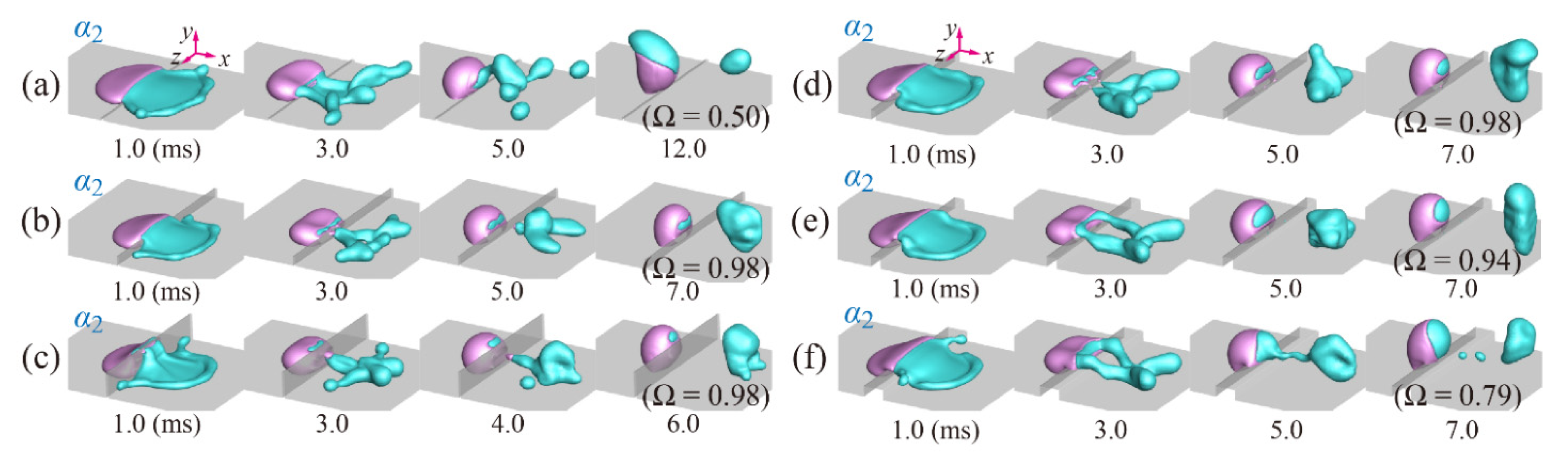
The initial bouncing directions of separated drops can depend on the impact velocity and viscosity ratio, as shown in
Figure 6a. To estimate the bouncing direction, we obtained sequential images of the top-view snapshots for different
Wew at the viscosity ratio of
α2. The right column of the figure indicates that separated drops present the velocity components of
−z-direction at low
Wew, whereas they present the velocity components of
+z-direction at high
Wew. For example, there is the strongest velocity component of
−z-direction at the
Wew thresholds (i.e.,
Wec,w = 34). The findings can be explained by the residence time depending on the impact velocity. After spreading, W-parts that still adhere to G-parts retract in
−z-direction at low
Wew. In this situation, the retraction time of the W-part is significant in increasing residence time. However, W-parts are being separated from G-parts during spreading at high
Wew. In this situation, the velocity components of
+z-direction can be dominant in the bouncing dynamics. We investigated bouncing angles with respect to
+z-direction as a function of
Wew for four distinct viscosity ratios, as shown in
Figure 6b. The bouncing angle decreases approximately from π to 3π/8 as
Wew increases approximately from 30 to 90, but it is almost independent of the viscosity ratio. Previous studies showed that the behavior of bouncing drops in the retracting process could be characterized by a constant momentum for a certain principle direction and that the momentum ratios were related to the initial direction of bouncing [
26]. We plotted in
Figure 6b the momentum ratios between the horizontal directions by introducing an expression as
where
pz,ret and
px,ret represent the characteristic constant momenta in
z- and
x-directions, respectively. The data from Equation (9) are in good agreement with those measured from the drop’s trajectories. The findings of the bouncing directions can provide a post-processing strategy to control drop bouncing in applications, such as liquid separation.
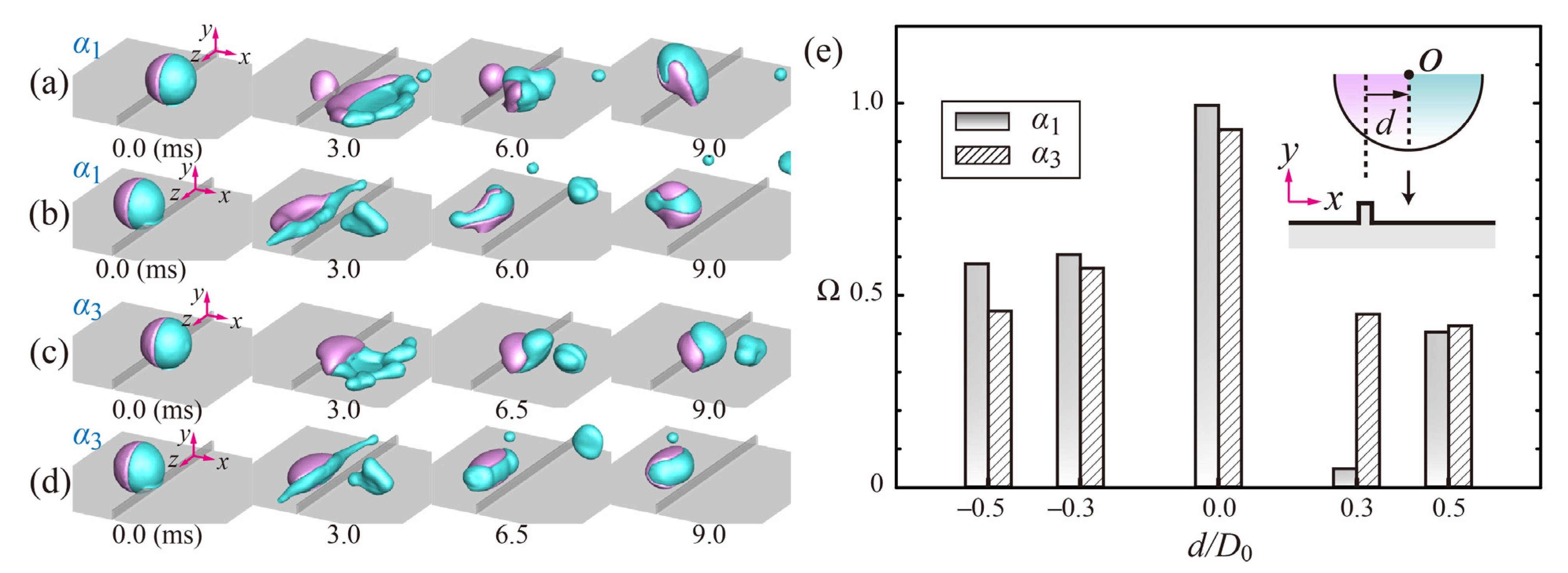
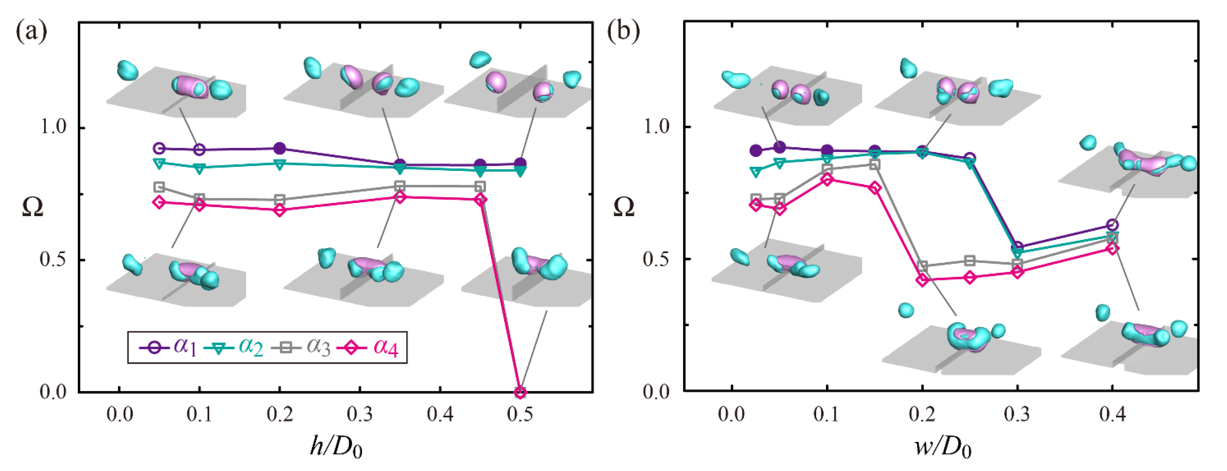
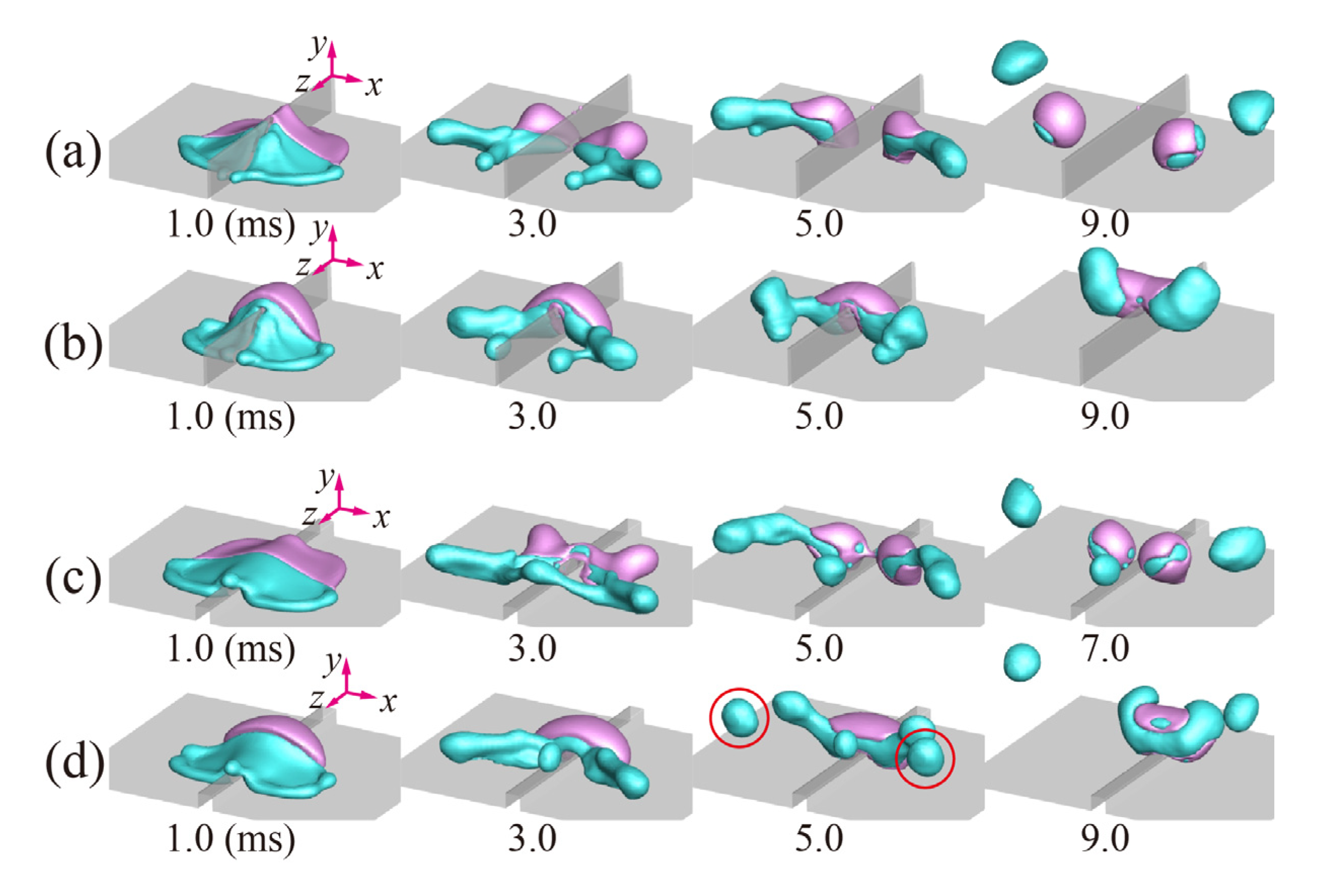
We investigated the effect of the height and width of the ridge on the separation efficiency under
h/D0 = 0.05 − 0.5 and
w/D0 = 0.025 − 0.4.
Figure 7a shows that approximately 70% or more of W-parts can be separated from G-parts at
h/D0 < 0.5 and that the low-viscosity ratio gives rise to the high Ω for any
h/D0. The bouncing dynamics on the tallest ridge of
h/D0 = 0.5 are shown in
Figure 8a,b. Drops with
α1 exhibit the normal separation mechanisms belonging to the high-
Wew regime, whereas drops with
α3 are not split because climbing of the G-part along the ridge causes weak relative velocities between two fluidic parts, as seen in the figures at 5.0–9.0 ms. Meanwhile, it is found in
Figure 7b that approximately 70% or more of W-parts can be separated from G-parts at
w/D0 < 0.2. The bouncing dynamics on the ridge with
w/D0 = 0.2 are shown in
Figure 8c,d. The W-parts of the drops with
α1 are split into two main separated drops on the surface and a small drop remaining on the ridge, as seen in
Figure 8c at 5.0–7.0 ms. However, drops with
α3 eject daughter drops at the end of W-parts (red circle), and the remaining W-parts with the reduced inertia retract toward G-parts, thereby leading to low Ω as depicted in
Figure 8d at 5.0–9.0 ms. Note that the high inertia of W-parts and long residence time of G-parts can be necessary to attain the high efficiency of the separation. The geometrical effect of the ridge on Ω can be stated as follows: the separation efficiency of Ω ≥ 0.7 can be secured with
h/D0 = 0.25 ± 0.2 and
w/D0 = 0.1 ± 0.05.
As an additional note, we studied the effect of the drop size, ridge size, and offset distance on the dynamics of Janus drops with an initial inclination of 0° against the ridgeline. For high heights and low widths of ridges, the W-part can be separated from the G-part with high efficiencies of the separation under the impact configurations. Details are described in
Appendix A.


