Review

A Review of Prestressed Fibre-Reinforced Polymer Matrix Composites

by
Raphael Olabanji Ogunleye
* and
Sona Rusnakova
Department of Production Engineering, Faculty of Technology, Tomas Bata University in Zlín, Vavrečkova 275, 760 01 Zlin, Czech Republic
*
Author to whom correspondence should be addressed.
Polymers 2022, 14(1), 60; https://doi.org/10.3390/polym14010060
Submission received: 2 December 2021 / Accepted: 21 December 2021 / Published: 24 December 2021
(This article belongs to the Special Issue Synthesis, Processing, Structure and Properties of Polymer Materials)

Abstract

:
This review examines various studies on reducing tensile stresses generated in a polymer matrix composite without increasing the mass or dimension of the material. The sources of residual stresses and their impacts on the developed composite were identified, and the different techniques used in limiting residual stresses were also discussed. Furthermore, the review elaborates on fibre-prestressing techniques based on elastically (EPPMC) and viscoelastically (VPPMC) prestressed polymer matrix composites, while advantages and limitations associated with EPPMC and VPPMC methods are also explained. The report shows that tensile residual stresses are induced in a polymer matrix composite during production as a result of unequal expansion, moisture absorption and chemical shrinkage; their manifestations have detrimental effects on the mechanical properties of the polymer composite. Both EPPMC and VPPMC have great influence in reducing residual stresses in the polymer matrix and thereby improving the mechanical properties of composite materials. The reports from this study provide some basis for selecting a suitable technique for prestressing as well as measuring residual stresses in composite materials.

1. Introduction

Composite materials are developed by combining materials offering unique properties that cannot be achieved individually by the constituent materials. Because of their excellent strength to weight ratio, they have increasingly been used as engineering materials for many applications, that include automotive and aerospace parts, construction materials, electrical parts and other consumer products [1]. The growth of composite materials for extended use, particularly in the aerospace and automobile industries, has necessitated continuous research for developing improved composites with excellent mechanical properties [2]. The constituents of composites are classified into matrix and reinforcement. While the matrix can be made of polymers, metals or ceramics, reinforcement includes fibres, whiskers and particulate fillers that exist in natural (lignocellulose, animal fibres and minerals) or synthetic form (carbon, aramid, boron, nylon, polyethylene) [3].
To produce a fibre-reinforced polymer composite, fibres of various configurations and stiffness are embedded into a polymer matrix of lower stiffness. While the fibre is responsible for carrying the load and offering much needed strength and stiffness, the polymer matrix is responsible for the mobility of the load to other parts of the fibre by providing the required binding forces [3]. The matrices also prevent the reinforced fibres from absorbing moisture, propagating micro-cracking due to microbial and chemical attacks. Polymer matrices can be either thermoplastic or thermoset. Thermoplastic polymers undergo a physical change when heated and can be softened and reformed. Some thermoplastics commonly used in composites include polyetheretherketone (PEEK), polyetherketoneketone (PEKK), polyphenylene sulphide, polyethylenimine (PEI) and polycarbonates (PC) [4]. On the other hand, thermoset polymers undergo a chemical change in the presence of a crosslinking agent (hardener) to form a three-dimensional structure. Thermosets include epoxies, phenolics, polyimides, polyester, vinyl ester, bismaleimide, melamine and silicone [4]. Thermoplastic composites offer great potential due to less processing time. However, significant drawbacks, which include a high processing temperature (the polymers must be heated to melting point to incorporate the fibre), a high tendency for the buckling of fibres in the polymer matrices, and solvent and fluid resistance features, have reduced their adoption as a substitute for thermoset in fibre-reinforced polymer composites [5].
Both tensile and compressive stresses are generated in polymer composite structures during the manufacturing process, and their occurrence in a composite can result from differences in physical and mechanical properties, a contraction of the polymer matrices before curing, manufacturing techniques and moisture absorption from the environment [6]. However, while compressive stresses have positive influences on the mechanical properties of the composite material, the tensile stresses have a detrimental effect on the manufactured polymer composite by causing distortion, dimensional instability and matrix cracking [7]. The residual stresses referred to in this study are the tensile residual stresses, and many techniques have reportedly been used in the literature to lessen the residual stresses in fibre-reinforced polymer (FRP) composites. Fibre-prestressing offers a low-cost means of reducing the influence of tensile residual stresses, thereby improving the mechanical properties without increasing the mass or dimension of the composite [8]. It is important to know that fibre-prestressing can only reduce residual stress in polymer composites if applied to a certain level [9]. Therefore, there has been continuous research on improving fibre-prestressing techniques.
This review explores the state-of-the-art fibre-prestressing techniques used in reducing residual stress in FRP composites. Moreover, the mechanism and methods used for improving the mechanical properties of FRP composites are examined.

2. Source of Residual Stresses in a Composite

In the absence of external forces, residual stresses are forms of stress that bring about the deformation of a composite material [7]. There are two primary sources of residual stresses in a composite material; (i) residual stresses generated due to differences in deformation-related properties of the materials, and (ii) production processes that induce residual stresses [9]. Moisture absorption, the chemical shrinkage of the matrix and a variation in the coefficient of thermal expansion induce residual stresses in polymer composites. Researchers have also shown that residual stresses can initiate failure in a composite material due to matrix cracking [10]. The influence of matrix cracking can lead to a dangerous failure, especially when the material is under loading conditions. Both compressive and tensile residual stresses are generated in composite materials. However, while compressive residual stresses help prevent cracks from spreading throughout the matrices, tensile residual stresses assist in the opening of micro-cracks in the polymer matrix [11]. Other defects such as fibre waviness, delamination, warping and dimensional imbalance are also due to residual stresses [12].
Many techniques have reportedly been used to reduce the effect of residual stresses in polymer composites. Process optimisation of cure cycle parameters such as dwell time, dwell temperature, dwell cycle and cooling rate can minimise residual stress during production [13,14,15]. Shape memory alloys (SMAs) also reduce stress concentration in FRP matrices. SMAs are novel metallic materials that can undergo reversible solid to solid change in a phase when subjected to thermal or mechanical loading that can cause sizeable inelastic strain [16]. They are generally available in the form of a wire with a diameter below 200 µm [17] and can be embedded in various configurations, as shown in Figure 1. SMAs offer other vital properties such as impact damage control, crack closure and shape morphing. Nevertheless, SMAs induce fibre misalignment and can create an uneven stress distribution in a composite [17].
Similarly, the electron beam curing technique composite can also reduce stress concentration [18]. The technique involves generating free radicals from a high-energy electron accelerator that propagates the polymerisation and crosslinking reaction at room temperature. Since the curing temperature is kept below the traditional thermal curing process temperature, the residual stress generated using an electron beam will be lowered [19]. Moreover, high processing electron beam curing results in an increased production rate and low shrinkage compared to that of conventional thermally cured composites [20]. To utilise the electron beam curing process, cationic initiators are required. Hence, the initiators—that are primarily Lewis or Bronsted acids—react when exposed to high energy electron irradiation. However, a high initiator concentration can lead to a thermal degradation of the polymer matrix, while excess irradiation can damage the fibre strength [21].
Despite their positive influences, electron beam cured composites cannot replicate some of the characteristics of thermally cured composites (high fracture toughness and inter-laminar shear strength) [20]. Similarly, expanding monomers have reportedly been used as anti-shrinkage in composite materials [22]. The polymerisation reaction of the polymer matrices results in a volumetric shrinkage of the matrices during the curing stage. The addition of the expanding polymer gives rise to volumetric expansion, thereby reducing volumetric shrinkage and residual stress [23,24]. The expanding monomers can also reduce the modulus and initiate the transverse cracking of composite materials [9]. Compared to the techniques mentioned above concerning the cost and simplicity, fibre-prestressing is relatively more acceptable.

3. Fibre-Prestressing Technique

There has been growing interest in improving the mechanical performance of FRP composites by minimising the induced stress without increasing the mass or dimension of the composite [8]. Since improving the composite performance increases the production cost, improving the production technique of composites through fibre-prestressing is a possible way of mitigating the cost [9]. Fibre-prestressing has been discovered by researchers as a productive method of reducing the effect of residual stresses in composite materials during production [25,26,27].
Fibre-prestressing can be achieved elastically or viscoelastically. The elastically prestressed polymer matrix composite (EPPMC) is achieved by subjecting the fibre material to the applied load and maintaining the load throughout the curing cycle of the polymer composite [28,29]. The load is released after the cooling and solidification of the composite at ambient temperature. Subsequently, the prestressed fibres tend to return to their initial length, generating compressive stresses in the matrix. These compressive stresses reduce the detrimental effect of the tensile residual stresses induced during the curing process [29]. In addition, the viscoelastically prestressed polymer matrix composite (VPPMC) is formed by subjecting polymeric fibres to a tension load, which introduces creep stress, and then removing the load before moulding the fibre to the polymer matrix. After the curing stage, prestressed fibres tend to return to their initial length, thereby creating compressive stresses that counterbalance the effect of induced tensile residual stresses [28]. The advantages and shortcomings of the two prestressing techniques are discussed further in the next section.

3.1. Elastically Prestressed Polymer Matrix Composite (EPPMC)

The fibres are prestressed by subjecting them to a force lower than the elastic limit of the fibre and maintaining this force throughout the curing cycle of the composite. After curing, the force is removed, and the fibres tend to return to their original states. Compressive stresses are developed within the solidified matrix due to the bonding of the prestressed fibre with the polymer matrix [30]. Various methods that have reportedly been used to elastically prestressed fibres are discussed in the next section.

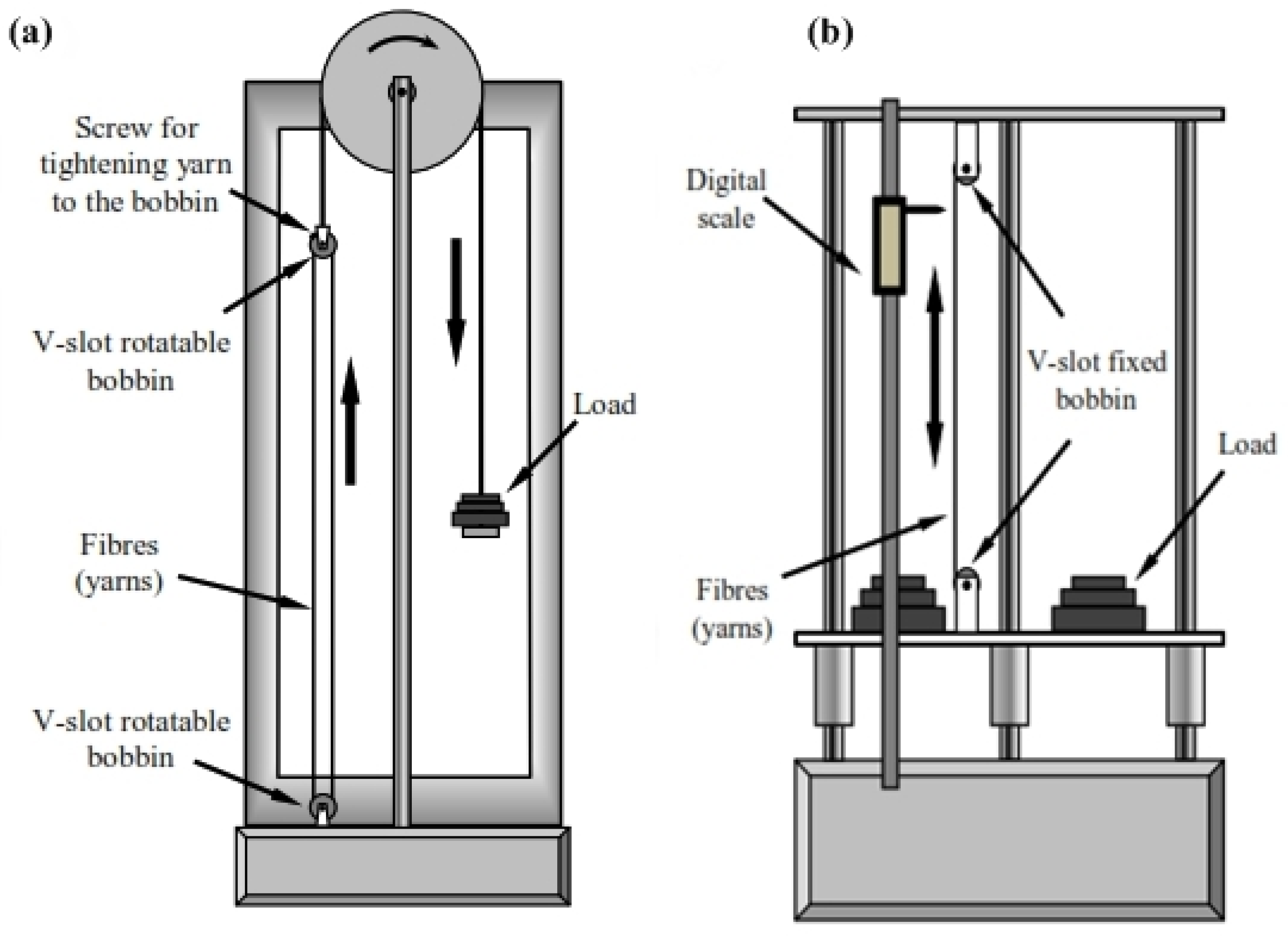
3.1.1. Deadweight Method

The deadweight prestressing method (Figure 2) was first presented by Jorge, Marques and De Castro [31]. They studied the influence of prestressing on the mechanical behaviour of a unidirectional polyester composite using E-glass fibre. The deadweight rig consists of steel pins arranged on a roving boundary, with the distance between the adjacent pin approximately equal to 2 mm. The fibres were rolled around the steel pins, and the two ends were subject to a load. The resin was applied, and the composite was cured at ambient temperature in an oven. Al-Dulaimy, Al-hassany and Shakir [32] utilised a similar prestressing technique using E-glass fibre and epoxy resin. The result obtained shows an increase in stiffness and a percentage elongation at break for the prestressed composite. Some of the shortcomings of using the deadweight method include the inability to obtain a uniform distribution of fibres in the polymer matrix and a fibre fracture tendency in the steel pin area when subjected to a bending force [33].

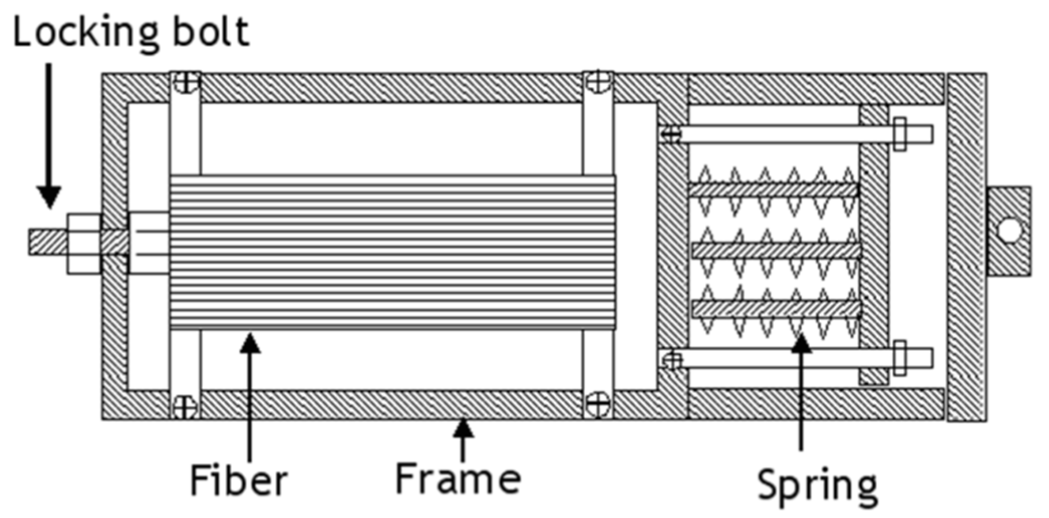
3.1.2. V-Slot Fastening Method

The V-slot consists of an aluminium plate with V-shaped slots at the two ends (Figure 3). Unlike the deadweight method, the V-slot fastening method can be used to prestress laminates because it can accommodate material with a large surface area [33]. Prepreg laminates are prestressed by laying them up between the plates, and both ends of the material are fastened using the V-shaped bar to the slot and finally cure in an autoclave or hot press. The major drawback to using this method is a tendency to fracture when brittle fibres are being prestressed due to twisting when fastened and a difficulty in determining the prestressing level [9]. Moreover, fibre fracture can lead to a non-uniform distribution of stresses in the composite [34].

3.1.3. Jack Prestress Rig Method

The Jack prestress rig method was presented by Abdullah and Hassan [35]. They studied the effect of varying prestressing levels on the strength of a carbon-fibre-reinforced composite laminate. The setup consists of a flat prestress surface connected to a pulling jack. The two ends of the fibre laminate were fixed to the base plate (2) and moving assembly (4), respectively (Figure 4). The tensile force needed to produce the required prestressing level was applied through the jack and the composite was cured in an oven. However, the assembly is designed to have a free movement which might cause fibre waviness during curing.

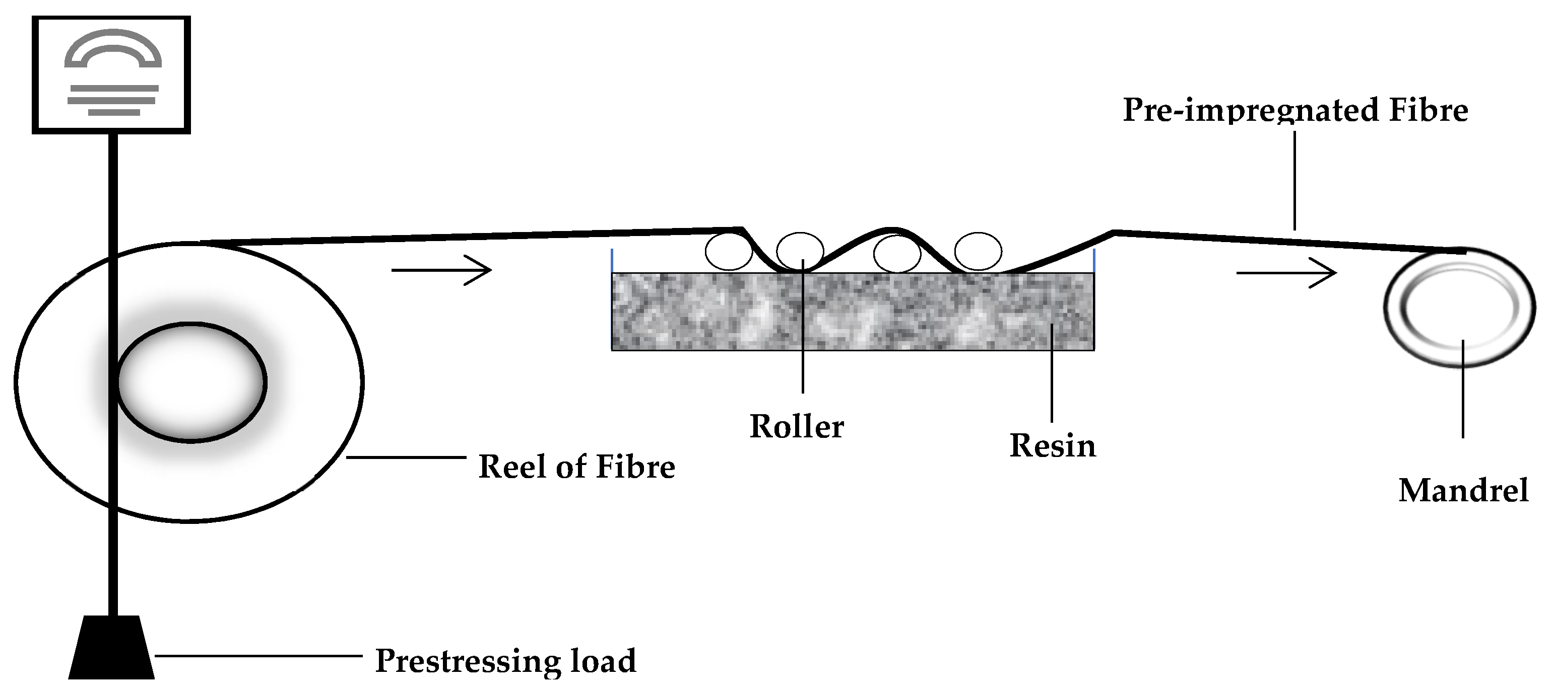
3.1.4. Filament Winding

In this technique, fibres roving are pulled with a known amount of load over a liquid resin bath and then warped on a mandrel to produce a composite material (Figure 5). Composites with different prestressing levels can be made using this technique by applying varying pre-load levels [36,37]. Following the winding step, the composite is cured in an oven or autoclave or by exposing it to infrared radiation [38]. Products from this technique can vary in complexity from a simple pipe to an aeroplane fuselage [39]. The primary benefit of filament winding is the ability to use automation and robots in performing operations [40]. The greatest drawback is the difficulty in obtaining an equal fibre volume fraction due to compression and loss of resin when each layer of the composite is being warped unto the mandrel [36]. Moreover, the mandrel stiffness affects the fibre pretension; therefore, it is not easy to maintain a constant load throughout the process [9]

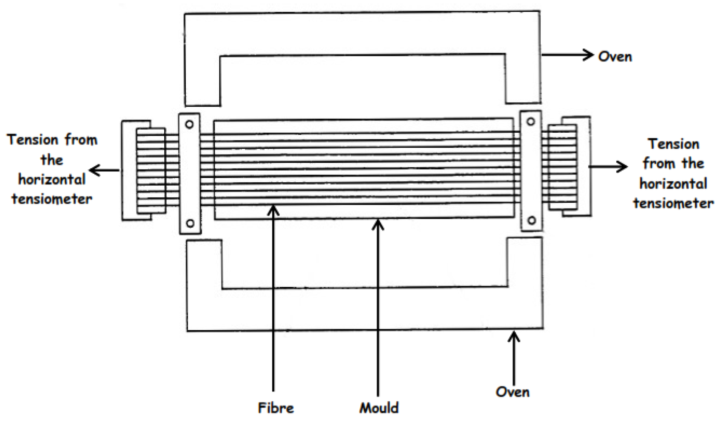
3.1.5. Biaxial Loading Frame and Fibre Stretching Rig

Jevons, Fernando and Kalsi [41] studied the effect of prestressing on the low-velocity impact performance of glass fibre composites using a biaxial loading frame (Figure 6). The setup is made of a C-channel consisting of four clamps joined to the frame by bolts. Prestressing levels are applied through a loading pin by making use of a mechanical test machine. The prestressed composite is clamped and tightened with a bolt to the frame, vacuum-bagged and cured in an autoclave [42]. As a result of the sharp edge of the frame, it is difficult to prepare the assembly for vacuum-bagging [43]. Moreover, maintaining a constant level of prestressing by using the tensile machine is not easy due to the limited amount of accessible space between the fixed and moveable jaws needed to place the prestressing frame inside the device [36].
Zhao and Cameron, [44] utilised a fibre-prestressing rig similar to the biaxial loading frame to prestress glass fibre-reinforced polypropylene. The fibres are wounded on the frame and preloaded using the tensile testing machine, and then the bolts are locked to achieve the required prestressing level (Figure 7).

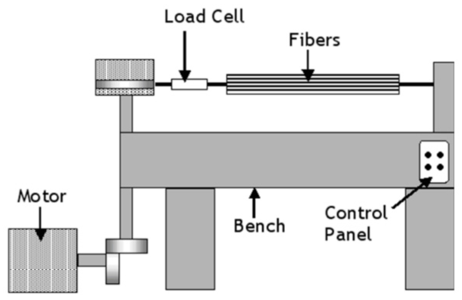
3.1.6. Horizontal Tensile Machine

Motahhari and Cameron [45] reported a fibre-prestressing technique using a horizontal tensile machine in studying micro-residual stresses in an E-glass fibre-reinforced epoxy polymer composite. The fibres were wound on two different grips before being transferred to a horizontal tensile machine (Figure 8) that provided applied forces, and then the epoxy resin was added directly to the fibre and curing was carried out in an oven (Figure 9). The principle seems simple, but it is challenging to maintain a uniform temperature profile. Furthermore, vacuum-bagging for autoclave curing will also be difficult due to the complex assembly.

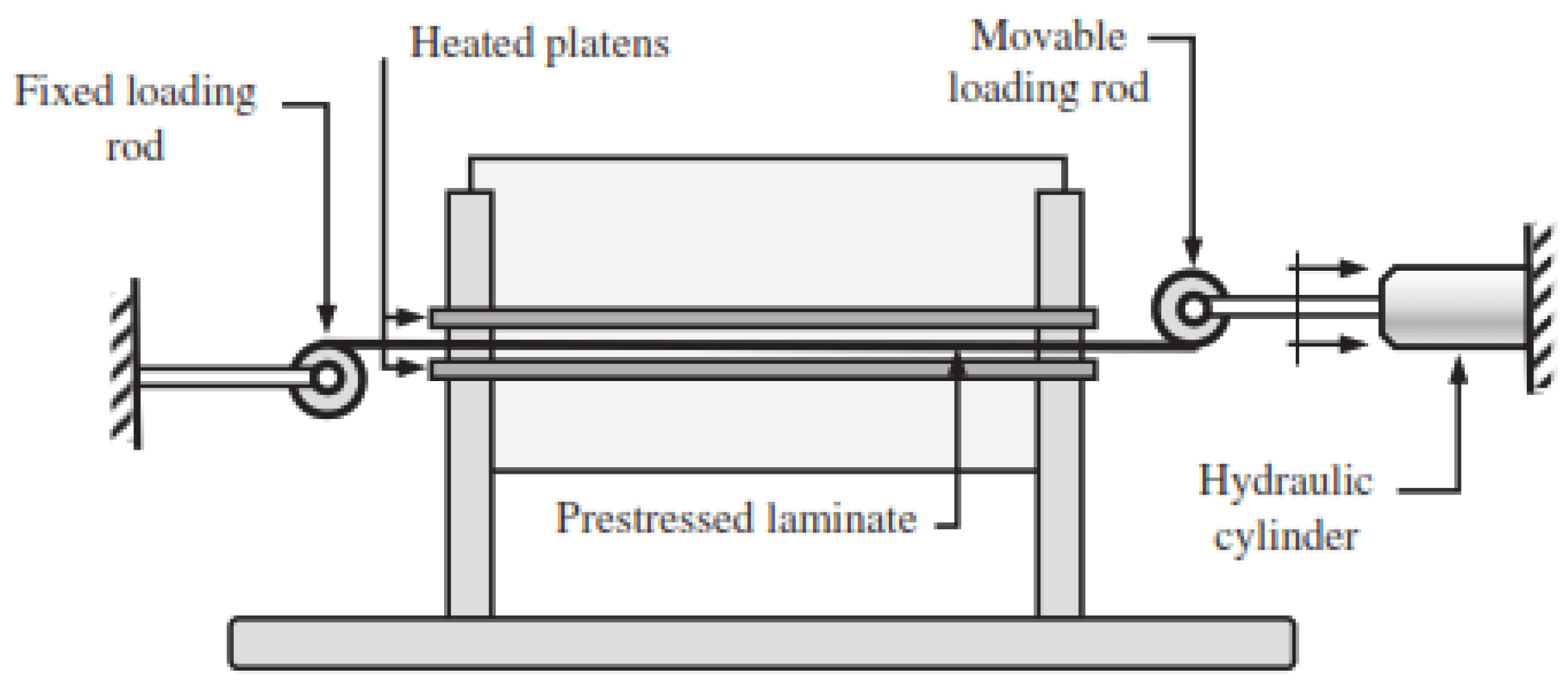
3.1.7. Hydraulic Prestressing Rig

Tuttle, Koehler and Keren [46] proposed a technique for fibre-prestressing using the hydraulic-cylinder-based prestressing rig shown in Figure 10. The machine consists of a movable rod connected to the hydraulic cylinder and a fixed loading rod at the other end. The prepreg was rolled around the movable rod while the tension was applied through the hydraulic cylinder that also controls the prestressing level. The technique allows the tension load to be applied only in one direction [35].

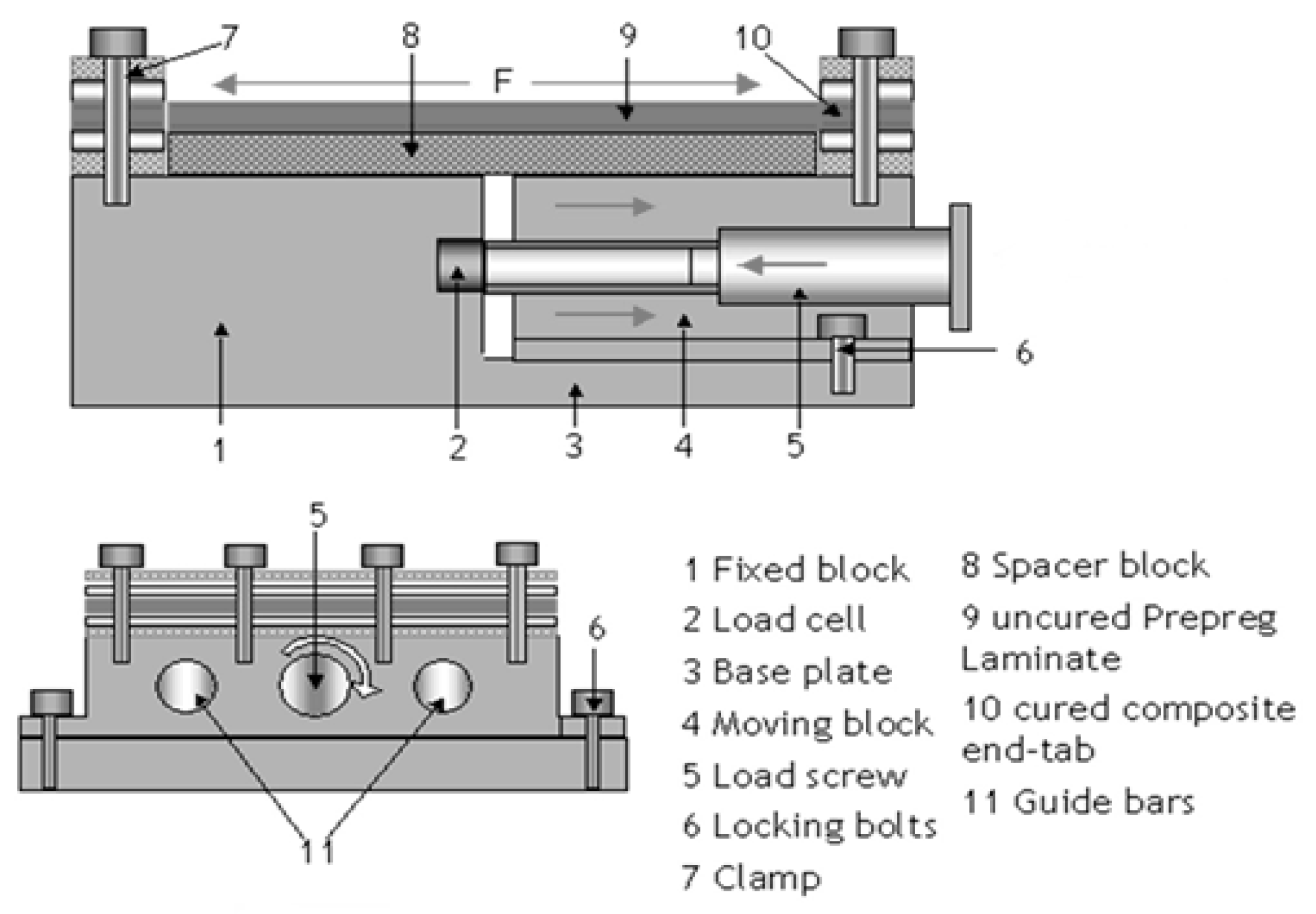
3.1.8. Flatbed Prestressing Rig

Krishnamurthy [35] prestressed E-glass fibre/Epoxy laminates using the flatbed prestressing rig shown in Figure 11. The laminates’ edges were cured by hot press and fixed to the rig by clamping with bolts. The loaded screw provided the tension while the laminate prestressing level was measured by the load cell (up to 150 MPa) and the autoclave was used for curing the laminate.
Fibre misalignments were identified close to the edge of the laminates due to the temperature variation between the hot press cure edge of the laminates and the remaining parts that were being cured in an autoclave [35]. The results of the requirement to subject the composite material to load throughout the curing process (EPPMC) provide the basis for the design of various prestressing techniques for a specific product geometry. Generally, EPPMC techniques can be applied to pre-impregnated fibre and both synthetic and natural fibres can be used. However, they are limited to continuous fibres, and there are constraints related to the product geometry [34].

3.2. Viscoelastically Prestressed Polymer Matrix Composite (VPPMC)

The technique involves using polymeric fibres to generate compressive stress in a composite material through the viscoelastic recovery process [47,48]. The fibres are prestressed by applying a load over a while to induce creep. After removal of the load, the fibres undergo a time-dependent elastic recovery. When the prestressed fibres are embedded in the polymer matrix and subjected to curing, the elastic recovery with the surrounding polymer matrix continues, thereby imparting compressive stresses that counterbalance the tensile residual stresses generated in the composite matrix [20]. Because the fibre stretching and moulding operations can be carried out independently, the technique offers flexibility in the geometry of the manufactured composite [49]. Based on previous studies, VPPMC can be classified into cellulose-fibre-based VPPMC (CFVPPMC) and synthetic polymeric fibre-based VPPMC (SPFVPPMC). CFVPPMC contain prestressed cellulose fibres predominantly from natural plants such as kenaf, sisal, flax, bamboo, jute, wheat straw, ramie and eucalyptus. Natural fibres are biodegradable and cheap and have a low density. Table 1 show physicomechnical properties of some natural and synthetic fibres commonly used in PMC.
Cui et al. [50] studied the flexural characteristics of the viscoelastically prestressed bamboo-sliver-reinforced parallel strand lumber (PSL). The flexural strength increases compared to the unprestressed counterparts. A similar result was obtained by Qin and Fancey [51] for viscoelastically prestressed cellulose yarn in a polyester casting resin matrix.
Širvaitienė et al. [52] also reported an increase in the flexural performance of viscoelastically prestressed vegetable fibre in PMC. However, due to moisture absorption, inadequate knowledge about the mechanism that controls natural fibre mechanical variations and the mode of failure, there is a limitation to their usage in polymer matrix composites [53].
Furthermore, high-performance synthetic polymer fibres are designed to resist a wide range of thermal, chemical and physical stress [58]. Nylon and ultra-high molecular weight polyethylene fibre (UHMPE) are common synthetic polymeric fibres used in polymer matrix composite development. Previous studies have shown that viscoelastically prestressed UHMPE and the Nylon 6.6 fibre enhanced the mechanical properties (strength and young modulus) of the PMC compare to their unstressed counterparts [59,60].
Unlike the EPPMC, in which the fibre-prestressing and curing operations are designed and carried out with the same assembly, VPPMC fibre stretching and moulding operations are decoupled therefore there is more flexibility in the fibre orientation (both continuous and short fibre can be used), distribution and material production. Many studies on VPPMC carried out fibre-prestressing using bespoke vertical stretching rigs (Figure 12). The creep and recovery strain for a small level of prestressing can be determined using the setup shown in Figure 12a, while higher level of fibre prestressing can be achieved using the rig shown in Figure 12b. The displacement gauge measures the strain and recovery rate by calculating the distance between two marks on the prestressed fibre yarn and the stretching rigs have the advantage of accommodating a wide variety of load levels required for prestressing operations [6]. On the contrary, the VPPMC technique is only applicable to fibres that have viscoelastic behaviour, and curing at elevated temperatures is not suitable to prevent a permanent deformation of the fibres [43].

3.3. Mechanical Properties of Prestressed PMC

Compared to other enhancing techniques, both of the two prestressing methods have shown their significance in improving the mechanical performance of composite material without increasing the mass or section dimension. Table 2 provides up-to-date findings and results of previous studies on fibre-prestressing techniques.

3.4. Residual Stresses Measurement

The continuous advancement in the development of composite materials has drawn more attention to prediction and measuring the distribution and sizes of residual stresses because the behaviour of composite materials is greatly influenced by these factors [72,73]. Residual stress development in the composites cannot be negligible; therefore, these can result in failure, especially when the tensile stresses generated become greater than the critical tensile strength of the material [74]. At this stage, microcracking can occur, thereby exposing the fibres to chemical and microbial attacks. Due to the nonlinear behaviour of composite material, it is difficult to measure some residual stresses that may result in material failure [75]. However, the effective measurement will reduce material failure and further enhance the research in the development of predictive control of residual stresses in composite material.
The measurement of residual stresses in the composite material can be achieved by modelling the entire production process or through the observation and measurement of the phenomena resulting in residual stress generation in a material. The latter method can be achieved through destructive and non-destructive testing. Table 3 highlights the difference between destructive and non-destructive testing techniques. The methods that are regarded as destructive typically require cutting, slitting or drilling operations to relieve the residual stresses. Afterwards, residual stresses are estimated by considering the dimensional changes that occurred. Table 4 shows some destructive and non-destructive testing methods that are commonly used to determine residual stresses in composite materials.
The layer removal method is an established method for measuring residual stresses by subjecting the material to deformation on one surface while the layers of the materials are removed from the other surface [76]. The surface of a completely equilibrated stressed component is gradually removed in layers. As a result, the portion is free of stress and a force imbalance is established throughout the system. The plate is then deformed to bring it back into balance, and the strain that results from that measurement is then utilised to quantify the amount of removed residual stress. By combining with other methods such as XRD, the layer removal method can offer information about the stress profile in a material [77]. However, this method can only assess residual stresses in materials with a simple geometry and on a macro-scale level [78].
Proposed by Mathar [79], hole drilling is commonly used in measuring residual stresses in a material. It is conducted by drilling a hole into a stressed material while the stresses relax, resulting in a change in the surrounding strain field that can be determined using a strain gauge and related to the relaxed stresses [79]. The hole-drilling method was initially designed for homogenous isotropic materials such as metals, but with a few modifications it may be used for composite, inhomogeneous and anisotropic materials, existing in both crystalline and amorphous form [80]. This method provides a more accurate measurement compared to other methods such as layer removal and ring-core methods. Moreover, the hole drilling method is less destructive because only a small portion of the central material is cut away during the deformation measurement. Likewise, it can determine the biaxial residual stresses distribution because the strain gauge is capable of identifying responses due to the biaxial surface strain of the material [81]. However, the hole-drilling method is more suitable for predicting residual stresses at the macro-scale, while it is difficult to predict at the micro-scale level of the material [82].
The hole-drilling method is divided into incremental hole drilling (IHD) and deep hole drilling (DHD). Incremental hole drilling is commonly used to measure residual stresses at varying degrees of thickness through an incremental depth drilling of the material [83]. On the contrary, deep-hole drilling involves drilling a reference hole through the material and measuring the deformation at the desired region [84]. The DHD method is faster compared to IHD but does not provide adequate insight to through-thickness residual stresses in a component, because it only provides an average residual stress over the entire depth. Thus, the IHD method is widely used compared to DHD [85]. Ghasemi, Taheri-Behrooz and Shokrieh [86] predicted non-uniform residual stresses within E-glass/Epoxy laminate composites using the incremental hole-drilling method, and the result obtained revealed that the strain at the surface decreased considerably compared to the strain released in the depth when the depth of the hole is increased. This result indicates that the residual stresses at each ply of the laminates affect the released strain of the underneath ply. A similar result was obtained by Sicot et al. [80] using carbon/epoxy cross-ply laminates, by studying the effect of increasing the drilling depth and the relative position of the strain gauge with a radius of the drilled hole. A widespread use of the hole-drilling method in determining residual stresses has led to the development of standard testing methods by The American Society for Testing and Materials (ASTM E837-20) [87].
Similarly, the ring-core method works the same way as the hole-drilling method. However, as opposed to drilling a hole, an annular groove is created, with a strain gauge rosette inserted in the middle of the groove to determine the elastic behaviour of the material [88]. The ring-core approach offers several advantages over the more popular hole-drilling technique when it comes to measuring residual stress. In the ring-core approach, more stress is released throughout the hole-drilling process, which allows for a more accurate assessment of the strain. Furthermore, because the stress concentration is reduced around the machined region, greater residual stresses can be recorded without surpassing the material’s yield stress. Additionally, the ring core method is tolerant of slight annular-hole diameter inaccuracies or eccentricity relative to the strain gauges. With this method, stress concentration effects are minimised, and it may measure stress levels close to the yield stress of the material. However, the diameter of the annular ring is relatively big, resulting in a significantly greater damage than the hole-drilling method. Because the diameter of the hole or ring determines the measuring region for residual stress, the results are also less localised.
One of the main drawbacks of the ring-core method is that it is more difficult to implement, especially when strain gauges are used, since the central wire gets in the way of the slot cutting process. Moreover, this technique has been limited to homogenous and isotropic materials [89]. The ring-core method has successfully been applied to quasi-isotropic FRP composites [90] and welded stainless steel [91]. Hence, it is obvious that the method continues to provide certain distinct advantages, especially at the micro-scale, and that additional study is required in this area to fully exploit its potentials.
The contour method is distinct among other methods used in measuring residual stresses by a relaxation mechanism because it offers detailed two-dimensional residual stress profiles that act on a plane of the material. To determine residual stresses using the contour method, the material is cut through the cross-sectional area by employing a wire Electro-Discharge Machining (EDM), and then the height maps of the cut surfaces are measured by using a laser profilometer or coordinate measuring machine. By cutting the material along the surface, residual stresses are released, resulting in deformation. The initially existent residual stresses parallel to the surface may be estimated using finite element analysis by evaluating the stresses necessary to restore the altered surface shape to a flat plane. The surface deformations are very small, and thus the EDM cutting and the surface height map measuring must be performed with very high accuracy. Furthermore, to prevent any asymmetry impacts, it is ideal to estimate the surfaces on both sides of the cut and to utilise the average surface height map. It is also feasible to make more cuts on perpendicular planes to acquire maps of the normal residual stresses along the planes. This method has been employed for measuring residual stresses in metal alloy melts [92], ion exchange glasses [93] and metal matrix composites [94]. However, the EDM cutting process can only be achieved if the material is electrically conductive, and therefore polymer-based and some fibre reinforcement, such as aramid, cannot be employed. Furthermore, the contour method can only measure uniaxial residual stresses, and it is difficult to apply the method to materials with a complex geometry [95].
The slitting method is another destructive testing method employed in measuring residual stresses. In several studies, this is also referred to as incremental slitting [96], crack compliance or compliance [97,98]. The method involves making a slit in a prestressed material and measuring the resulting deformation normal to the direction of the slit by using a strain gauge. The key advantage of using this method is its simple and non-complex procedure, its applicability to wide ranges of materials and its capability of measuring high-magnitude residual stresses. However, the slitting method application is limited to materials with reduced thickness. Therefore, it cannot adequately measure residual stresses in the materials at a macro-scale level [99].
It is standard practice in the microelectronics industry to employ Micro-Raman Spectroscopy to identify regions of mechanical stress in silicon circuit board components [100]. Chemical bonds in crystals may be studied using Raman spectroscopy, which employs light scattering to look at the vibrational energy of the chemical bonds. Raman peaks may be seen in the light scattered by the object. Any externally applied strain alters the location of these peaks. Consequently, the difference in Raman peak location between an unstressed and a stressed sample may be used to measure the applied strain. Moreover, the distribution of molecule orientations in the polymer matrix may be used to assess the strain in the amorphous polymer matrix [101]. Amorphous materials such as thermosetting polymers or glass have Raman peaks that are broad and irregular. Thermal plastics, on the other hand, have more clearly defined Raman peaks [89].
Furthermore, the X-ray diffraction method is another important technique used in measuring residual stresses in materials. This method can measure the residual stresses at the material surfaces up to a depth of 30 microns [102]. However, for deeper depth measurement, the removal of layers in the sample is required, which renders the process destructive. XRD determines the strain in the crystal lattice of a material through the examination of the change in crystal spacing. A diffracted X-ray beam may be generated by X-rays dispersed from a polycrystalline material; therefore, optimum diffracted intensities are recorded at certain angles. The diffraction plane’s inter-planar distance may be calculated from these angles by applying Bragg’s law [102]. Generally, samples with residual stresses have a spacing that is different from that of unstressed samples. Some of the advantages of using the XRD method are its simplicity and quickness in applying the process. Furthermore, the method can be applied to materials with complex shapes, and high-magnitude residual stresses at both micro and macro scales can be accurately predicted. However, the XRD method is only suitable for polycrystalline materials and the accuracy measurements can be affected by the grain size and texture [96,99]. The XRD method has reportedly been used to measure residual stresses in alloys [100,103], glass–ceramic matrix composites [104] and graphite–polymer matrix composites [105].
In addition, neutron diffraction (ND) is a method that uses neutron beam diffraction to identify deep-seated residual stresses in materials. As with X-ray diffraction, neutron diffracted beams follow Bragg’s Law, allowing stress-induced variations in atomic lattice spacing to be detected. As a result, the relative spacing differences are calibrated using a stress-free material sample to compute actual stress values. In comparison to X-rays, neutrons have the benefit of measuring residual stresses in materials at high depth and precision. The Synchrotron X-ray Method operates with the same principle as the XRD and ND discussed above.
It is a common phenomenon to employ ultrasound waves in the detection of faults in engineering materials [106], but they may also be used to quantify applied and residual loads [107]. To effectively assess stress levels in a material, it is necessary to precisely measure the time-of-flight change of an ultrasonic wave travelling between the stressed and unstressed areas of that material. To obtain an absolute measurement of stress, the time-of-flight measurement in the stressed material is compared to that in the unstressed material. The method has the advantage of measuring high-magnitude residual stresses. The measuring procedure is fast and tri-axial residual stresses can be measured [107]. However, the ultrasonic method supports only crystalline materials, is extremely sensitive to changes in the microstructure and not suitable for components with complex shapes [107].
Table 4. Common destructive and non-destructive test methods used in the calculation of residual stresses in composites.
MethodsPrincipleMaterialShortcomingsReferences
Layer Removal
(DT)
It monitors the elastic response of a laminate to the release of residual stressesCeramics
Metals
Polymers
Composites
Additional stresses can be imparted to the test sample due to the machining of the composite surfaces.
Limited to macro-scale residual stresses
[76,78]
Hole drilling
(SDT)
Drilling of a hole into the stressed object releases the stresses, leading to changes in the surrounding strain field that may be measured and related to the relaxed stresses.Ceramics
Metals
Polymers
Composites
It requires several assumptions to simplify the result solution.
Accurate measurement around the hole, especially in the fibre direction, is very challenging.
Limited to macro-scale residual stress measurement
[80,82,108]
Ring-Core Method
(SDT)
It follows a principle comparable to the hole-drilling method. However, instead of discharging residual stresses by drilling a hole and measuring the elastic reaction of the surrounding material, the ring-core method discharges stress by cutting an annular groove into the surface of a component that contains residual stress.Metals
Ceramics
Polymers
Limited to homogenous and isotropic material. [109]
Contour Method
(DT)
The material is sliced through by a planar surface, releasing residual stresses across the plane. As a result, the surface experiences out-of-plane deformation, which is recorded, and the underlying residual stresses across the cut are calculated using the finite element technique.Ceramics
Metals
Plastics
Composites
Difficulty in measuring residual stresses close to the surface of the material.
Not suited for small components.
[95]
Slitting Method
(DT)
A tiny slit is cut into a prestressed sample, and the resultant deformation parallel to the slot’s direction induced by the restoration of force equilibrium is determined. The repetition of this procedure at increasing depths allows for the determination of residual stress across the component’s thickness.Ceramics
Metals
Plastics
Composites
Macro-scale residual stresses cannot be fully measured.
Only average stress along the transverse direction (y-axis) can be measured.
[110]
Neutron Diffraction Method
(NDT)
Raman spectroscopy employs light scattering to measure the vibrational energy of crystalline chemical bonds. The dispersed light is detected, and typical Raman peaks may be detected. Any externally imposed strain alters the position of these peaks. Consequently, a stressed and unstressed sample’s Raman peak position variations may be used to calculate the applied strain.Metal
Ceramics
Composites
Resolution is limited, and residual stress changes smaller than 1 mm cannot be measured.
Not suitable for amorphous materials
[111]
Raman Spectroscopy Method
(NDT)
Stresses are determined by monitoring the frequency of certain luminescence peaks in comparison to those in an unstressed state.Ceramics
Polymers
Composites
Limited to macro-scale residual stresses measurement.[112]
X-ray Diffraction Method (NDT)
(destructive if used for measuring depth)
When residual stress is determined using X-ray diffraction (XRD), the strain in the crystal lattice is determined and the related residual stress is calculated using the elastic constants, assuming that the relevant crystal lattice plane exhibits linear elastic deformation.Metal
Ceramics
Composites
Applicable to polycrystalline materials only.
The accuracy of this method is affected by the texture and grain size.
Measurement is limited to the surface of the material
[113]
Synchrotron X-ray Method
(NDT)
Similar to the X-ray diffraction method. However, X-rays are far more intense and have a much greater energy, and their tremendous energy allows them to penetrate much farther into materials.Metal
Ceramics
Composites
Applicable to polycrystalline materials only
[114]
Ultrasonic Method
(NDT)
The material is subjected to an ultrasonic (acoustic) wave, which is then detected by reflection, transmission or scattering. To determine the magnitude of stresses, the velocity of an ultrasonic wave in some modes is evaluated.Metals
Ceramics
Composites
Not suitable for amorphous materials.
Limited to macro-scale residual stress measurement.
[115]
DT: Destructive testing, SDT: Semi-destructive testing, NDT: Non-destructive testing.

4. Potential Applications and Prospects

Fibre-reinforced materials are used for many engineering applications where high mechanical properties are required. The use of carbon-fibre-reinforced polymer composites may reduce the weight of the materials up to 70% compared to steel [116]. Therefore, exploring such materials in making aeroplane and car parts provides the potential for minimising fuel consumption and carbon dioxide emission. Due to the high-impact energy absorption behaviour, prestressed fibre polymer composites can be used for ballistic protection in armours, vests and automobiles. Kevlar-based polymer matrix composites are materials used for ballistic protection [117]. It is well known that prestress induces an energy-absorbing mechanism at the fibre–polymer matrix interface [48], thereby increasing the impact absorption of the composite material.
Crashworthiness is an automobile’s capacity to protect its occupants from severe injury or death in the event of a given number of collisions. It is a quantitative assessment of a structure’s ability to protect its passengers in survivable crashes [118]. It is an essential factor that needs to be considered in selecting the material for vehicular structural assembly [119]. Material crashworthiness is characterised in terms of its energy absorption capacity (EAC). Generally, polymer composites have a high EAC compared to metals, and they can release deformation absorption energy during impact [120]. Prestressed fibres enhance the energy absorption capability of composite materials [70]. Moreover, the application of EPPMC and VPPMC technology in fibre-reinforced concrete development can enhance the resistance to crack propagation in a concrete structure. Bistable composite materials, which are often utilised in the aerodynamic control of aircraft and wind turbine blades, have drawn growing attention in recent years. They can be effectively manufactured utilising prestressed fibre technology [49]. The emerging developments will be toward alternate fibre materials, hybridisation, process optimisation and the use of a cost-effective fibre-prestressing technique.

5. Conclusions

The present article reviews some of the studies related to the techniques associated with fibre-prestressing in polymer matrix development. The presence of tensile residual stresses during the manufacturing process has a detrimental effect on composite materials’ performance, especially when subjected to an external load. Fibre-prestressing offers the advantage of minimising residual stress without increasing the mass or section dimension in composite materials. It involves generating compressive residual stresses in a fibre–polymer matrix interface to minimise the effect of tensile residual stresses. While fibre-prestressing can be achieved both elastically (EPPMC) and viscoelastically (VPPMC), several equipment designs have reportedly been used to achieve prestressing. Despite some limitations associated with these techniques, the influence of fibre-prestressing on polymer composite structural properties has been positive. Previous studies on prestressed composites have reported up to 60% increase in the tensile modulus, 62% increase in impact strength, 140% increase in tensile strength, 50% in the flexural modulus, 9% increase in compressive strength and an increase of more than 150% in fatigue life compare to their unprestressed composite counterparts.
Moreover, various methods have been reported for measuring residual stresses in materials. These are generally grouped into destructive and non-destructive methods. The destructive methods measure residual stresses by monitoring the response of a material to deformation, while non-destructive methods monitor the change in material structures when under the influence of residual stresses. The selection of the right method depends on the type of material (metals, plastics, ceramics, composites), material structure (Crystalline or amorphous), states of stresses, speed and measurement accuracy. Out of these methods, the hole-drilling method has been widely used due to its versatility and the availability of scientific standards for measuring residual stresses in various materials.

Author Contributions

Investigation, R.O.O. and S.R.; resources, R.O.O. and S.R.; writing—original draft preparation, R.O.O.; writing—review and editing, R.O.O. and S.R.; supervision, S.R. All authors have read and agreed to the published version of the manuscript.

Funding

The work received financial support from the “Internal grant of TBU in Zlín No. IGA/FT/2022/007” funded from the resources of specific university research and was completed in connection with the project “Innovative and additive manufacturing technology—new technological solutions for 3D printing of metals and composite materials,” registration no. CZ.02.1.01/0.0/0.0/17_049/0008407 financed by the Structural Funds of European Union project.

Institutional Review Board Statement

Not applicable.

Informed Consent Statement

Not applicable.

Data Availability Statement

The data presented in this study are available on request from the corresponding author.

Acknowledgments

This work and the project were realised with the financial support of the “Internal grant of TBU in Zlín No. IGA/FT/2022/007”, funded by the resources of specific university research and completed in connection with the project “Innovative and additive manufacturing technology—new technological solutions for 3D printing of metals and composite materials,” registration no. CZ.02.1.01/0.0/0.0/17_049/0008407, financed by the Structural Funds of the European Union project.

Conflicts of Interest

The authors declare no conflict of interest.

References

  1. Grzesik, W. Advanced Machining Processes of Metallic Materials Theory, Modelling, and Applications, 2nd ed.; Elsevier: Amsterdam, The Netherlands, 2017. [Google Scholar]
  2. Maria, M. Advanced Composite Materials of the Future in Aerospace Industry. INCAS Bull. 2013, 5, 139–150. [Google Scholar] [CrossRef]
  3. Chawla, K.K. Composite Materials, 3rd ed.; Springer: New York, NY, USA, 2012. [Google Scholar] [CrossRef]
  4. Wu, H.; Fahy, W.P.; Kim, S.; Kim, H.; Zhao, N.; Pilato, L.; Koo, J.H. Recent Developments in Polymers/Polymer Nanocomposites for Additive Manufacturing. Prog. Mater. Sci. 2020, 111, 100638. [Google Scholar] [CrossRef]
  5. Campbell, F.C. Manufacturing Processes for Advanced Composites. In Manufacturing Processes for Advanced Composites; Elsevier: Amsterdam, The Netherlands, 2004. [Google Scholar] [CrossRef]
  6. Fazal, A. Polymer Fibre Composites: Investigation into Performance Enhancement through Viscoelastically Generated Pre-Stress. Ph.D. Thesis, The University of Hull, Hull, UK, 2014. [Google Scholar]
  7. Parlevliet, P.P.; Bersee, H.E.N.; Beukers, A. Residual Stresses in Thermoplastic Composites–A Study of the Literature. Part III: Effects of Thermal Residual Stresses. Compos. Part A 2007, 38, 1581–1596. [Google Scholar] [CrossRef]
  8. Mohamed, M.; Selim, M.M.; Ning, H.; Pillay, S. Effect of Fibre Prestressing on Mechanical Properties of Glass Fibre Epoxy Composites Manufactured by Vacuum-Assisted Resin Transfer Moulding. J. Reinf. Plast. Compos. 2019, 39, 21–30. [Google Scholar] [CrossRef]
  9. Mostafa, N.H.; Ismarrubie, Z.N.; Sapuan, S.M.; Sultan, M.T.H. Fibre Prestressed Polymer-Matrix Composites: A Review. J. Compos. Mater. 2016, 51, 39–66. [Google Scholar] [CrossRef]
  10. Tan, S.C.; Nuismer, R.J. A Theory for Progressive Matrix Cracking in Composite Laminates. J. Compos. Mater. 1989, 23, 1029–1047. [Google Scholar] [CrossRef]
  11. Zhou, N.; Peng, R.L.; Schönning, M.; Pettersson, R. SCC of 2304 Duplex Stainless Steel—Microstructure, Residual Stress and Surface Grinding Effects. Materials 2017, 10, 221. [Google Scholar] [CrossRef] [PubMed] [Green Version]
  12. Russell, J.D.; Madhukar, M.S.; Genidy, M.S.; Lee, A.Y. A New Method to Reduce Cure-Induced Stresses in Thermoset Polymer Composites, Part III: Correlating Stress History to Viscosity, Degree of Cure, and Cure Shrinkage. J. Compos. Mater. 2000, 34, 1926–1947. [Google Scholar] [CrossRef]
  13. Shah, P.; Halls, V.; Zheng, J.; Batra, R. Optimal Cure Cycle Parameters for Minimizing Residual Stresses in Fibre-Reinforced Polymer Composite Laminates. J. Compos. Mater. 2018, 52, 773–792. [Google Scholar] [CrossRef]
  14. Ali, H.; Ghadbeigi, H.; Mumtaz, K. Processing Parameter Effects on Residual Stress and Mechanical Properties of Selective Laser Melted Ti6Al4V. J. Mater. Eng. Perform. 2018, 27, 4059–4068. [Google Scholar] [CrossRef] [Green Version]
  15. Mann, B.; Ford, K.; Neilsen, M.; Kammler, D. Minimizing Residual Stress in Brazed Joints by Optimizing the Brazing Thermal Profile. In Volume 2A: Advanced Manufacturing. Am. Soc. Mech. Eng. 2020, 84485, V02AT02A035. [Google Scholar] [CrossRef]
  16. Schrooten, J.; Michaud, V.; Parthenios, J.; Psarras, G.; Galiotis, C.; Gotthardt, R.; Humbeeck, J. Progress on Composites with Embedded Shape Memory Alloy Wires. Mater. Trans. 2002, 43, 961–973. [Google Scholar] [CrossRef] [Green Version]
  17. Cohades, A.; Michaud, V. Shape Memory Alloys in Fibre-Reinforced Polymer Composites. Adv. Ind. Eng. Polym. Res. 2018, 1, 66–81. [Google Scholar] [CrossRef]
  18. Raghavan, J. Evolution of Cure, Mechanical Properties, and Residual Stress during Electron Beam Curing of a Polymer Composite. Compos. Part A 2009, 40, 300–308. [Google Scholar] [CrossRef]
  19. Razavi, S.M.; Ahmadi, S.J.; Rahmani Cherati, P.; Hadi, M.; Ahmadi, S.A.R. Effect of Electron Beam Irradiation on Mechanical Properties of Unsaturated Polyester/Nanoclay Composites Reinforced with Carbon and Glass Fibres. Mech. Mater. 2020, 141, 103265. [Google Scholar] [CrossRef]
  20. Wolff-Fabris, F.; Altstadt, V.; Arnold, U.; Doring, M. Electron Beam Curing of Composites; Hanser Publshers: Cincinnati, OH, USA, 2010. [Google Scholar]
  21. Zhang, J.; Duan, Y.; Wang, B.; Zhang, X. Interfacial Enhancement for Carbon Fibre Reinforced Electron Beam Cured Polymer Composite by Microwave Irradiation. Polymer 2020, 192, 122327. [Google Scholar] [CrossRef]
  22. Orso, J.; Vizzini, J.A. Stress Effects of Inhomogeneous Expansion-Controlled Matrices in Continuous Fiber Composites. J. Compos. Mater. 1995, 29, 2003–2004. [Google Scholar] [CrossRef]
  23. Marx, P.; Wiesbrock, F. Expanding Monomers as Anti-Shrinkage Additives. Polymers 2021, 13, 806. [Google Scholar] [CrossRef]
  24. Fu, J.; Liu, W.; Hao, Z.; Wu, X.; Yin, J.; Panjiyar, A.; Liu, X.; Shen, J.; Wang, H. Characterization of a Low Shrinkage Dental Composite Containing Bismethylene Spiroorthocarbonate Expanding Monomer. Int. J. Mol. Sci. 2014, 15, 2400–2412. [Google Scholar] [CrossRef] [Green Version]
  25. Sokairge, H.; Elgabbas, F.; Rashad, A.; Elshafie, H. Long-Term Creep Behaviour of Basalt Fibre Reinforced Polymer Bars. Constr. Build. Mater. 2020, 260, 120437. [Google Scholar] [CrossRef]
  26. Zaidi, B.M.; Magniez, K.; Miao, M. Prestressed Natural Fibre Spun Yarn Reinforced Polymer-Matrix Composites. Compos Part A 2015, 75, 68–76. [Google Scholar] [CrossRef]
  27. Dvorak, G.; Suvorov, A. The Effect of Fiber Pre-Stress on Residual Stresses and the Onset of Damage in Symmetric Laminates. Compos. Sci. Technol. 2000, 60, 1129–1139. [Google Scholar] [CrossRef]
  28. Qin, Y.; Fancey, K.S. Drop Weight Impact Behaviour of Viscoelastically Prestressed Composites. Compos Part A 2020, 131, 105782. [Google Scholar] [CrossRef]
  29. Ge, C.; Wang, B.; Fancey, K.S. An Evaluation of the Scanning Electron Microscope Mirror Effect to Study Viscoelastically Prestressed Polymeric Matrix Composites. Mater. Today Commun. 2017, 12, 79–87. [Google Scholar] [CrossRef]
  30. Fazal, A.; Fancey, K.S. UHMWPE Fibre-Based Composites: Prestress-Induced Enhancement of Impact Properties. Compos. Part B 2014, 66, 1–6. [Google Scholar] [CrossRef] [Green Version]
  31. Jorge, L.D.A.; Marques, A.T.; De Castro, P.M.S.T. The Influence of Prestressing on the Mechanical Behaviour of Unidirectional Composites. In Developments in the Science and Technology of Composite Materials; Springer: Dordrecht, The Netherlands, 1990; pp. 897–902. [Google Scholar] [CrossRef]
  32. Al-Dulaimy, A.; Khalid, M.A.; Al-hassany, M.O.A.; Shakir, S.W. The Effect of Unidirectional Pre-Load on Tensile Characteristics of E-Glass Fibre and Epoxy Composite. Mater. Today Proc. 2021, 42, 2510–2515. [Google Scholar] [CrossRef]
  33. Hassan, F.A.K.; Abdullah, O.A. New Methodology for Prestressing Fiber Composites. Univers. J. Mech. Eng. 2015, 3, 252–261. [Google Scholar] [CrossRef] [Green Version]
  34. Krishnamurthy, S. Pre-Stressed Advanced Fibre Reinforced Composites Fabrication and Mechanical Performance. Ph.D. Thesis, Cranfield University, Silsoe, UK, 2006. [Google Scholar]
  35. Abdullah, O.A.; Hassan, A.K.F. Effect of Prestress Level on the Strength of CFRP Composite Laminate. J. Mech. Sci. Technol. 2016, 30, 5115–5123. [Google Scholar] [CrossRef]
  36. Kang, C.; Shi, Y.; Deng, B.; Yu, T.; Sun, P. Determination of Residual Stress and Design of Process Parameters for Composite Cylinder in Filament Winding. Adv. Mater. Sci. Eng. 2018, 1, 1–11. [Google Scholar] [CrossRef] [Green Version]
  37. Toptaş, E.; Akkuş, N. Damage Detection of Carbon Fibers in Filament Winding Machines Using an Electrical Resistance Method. Int. J. Adv. Manuf. Technol. 2017, 93, 671–679. [Google Scholar] [CrossRef]
  38. Korotkov, V.N.; Chekanov, Y.A.; Rozenberg, B.A. The Simultaneous Process of Filament Winding and Curing for Polymer Composites. Compos. Sci. Technol. 1993, 47, 383–388. [Google Scholar] [CrossRef]
  39. Ilangovan, S.; Senthil Kumaran, S.; Naresh, K. Effect of Nanoparticles Loading on Free Vibration Response of Epoxy and Filament Winding Basalt/Epoxy and E-Glass/Epoxy Composite Tubes: Experimental, Analytical and Numerical Investigations. Mater. Res. Express 2020, 7, 025007. [Google Scholar] [CrossRef]
  40. Wong, J.C.; Blanco, J.M.; Ermanni, P. Filament Winding of Aramid/PA6 Commingled Yarns with in Situ Consolidations. J. Thermoplast. Compos. Mater. 2018, 31, 465–482. [Google Scholar] [CrossRef]
  41. Jevons, M.; Fernando, G.; Kalsi, G. Effect of Pre-Tensioning on the Low-Velocity Impact Performance of Glass Fibre Composites. In Proceedings of the Tenth European Conference on Composite Materials (ECCM-10), Brugge, Belgium, 3–7 June 2002; pp. 3–7. [Google Scholar]
  42. Krishnamurthy, S.; Badcock, R.; Machavaram, V.; Fernando, G. Monitoring Pre-Stressed Composites Using Optical Fibre Sensors. Sensors 2016, 16, 777. [Google Scholar] [CrossRef] [Green Version]
  43. Mostafa, N.H.; Ismarrubie, Z.N.; Sapuan, S.M.; Sultan, M.T.H. Effect of Fabric Biaxial Prestresses on the Fatigue of Woven E-glass/Polyester Composites. Mater. Des. 2016, 92, 579–589. [Google Scholar] [CrossRef] [Green Version]
  44. Zhao, J.; Cameron, J. Polypropylene Matrix Composites Reinforced with Pre-Stressed Glass Fibres. Polym. Compos. 1998, 19, 218–224. [Google Scholar] [CrossRef]
  45. Motahhari, S.; Cameron, J. Measurement of Micro-Residual Stresses in Fiber-Prestressed Composites. J. Reinf. Plast. Compos. 1997, 16, 1129–1137. [Google Scholar] [CrossRef]
  46. Tuttle, M.E.; Koehler, R.T.; Keren, D. Controlling Thermal Stresses in Composites by Means of Fiber Prestress. J. Compos. Mater. 1996, 30, 486–502. [Google Scholar] [CrossRef]
  47. Osman, B.; Tian, Z.; Jiang, G.; Sun, X.; Carroll, A. Experimental Study on Dynamic Properties of UHMWPE and PVA Fibers Concrete. KSCE J. Civ. Eng. 2020, 24, 2993–3011. [Google Scholar] [CrossRef]
  48. Fazal, A.; Fancey, K.S. Performance Enhancement of Nylon/Kevlar Fibre Composites through Viscoelastically Generated Pre-stress. Polym. Compos. 2014, 35, 931–938. [Google Scholar] [CrossRef] [Green Version]
  49. Wang, B.; Ge, C.; Fancey, K.S. Snap-through Behaviour of a Bistable Structure Based on Viscoelastically Generated Prestress. Compos. Part B Eng. 2017, 114, 23–33. [Google Scholar] [CrossRef]
  50. Cui, H.X.; Guan, M.J.; Zhu, Y.X.; Zhang, Z.Z. The Flexural Characteristics of Prestressed Bamboo Slivers Reinforced Parallel Strand Lumber (PSL). Key Eng. Mater. 2012, 517, 96–100. [Google Scholar] [CrossRef]
  51. Qin, Y.; Fancey, K.S. Towards “Green” Viscoelastically Prestressed Composites: Cellulose Fibre Reinforcement. Compos. Part B Eng. 2018, 154, 439–448. [Google Scholar] [CrossRef]
  52. Širvaitienė, A.; Jankauskaitė, V.; Bekampienė, P.; Norkaitis, J. Vegetable Fibre Pre-Tensioning Influence the Composites Reinforcement. Polym. Compos. 2013, 34, 1533–1537. [Google Scholar] [CrossRef]
  53. Herrera-Franco, P.J.; Valadez-González, A. Mechanical Assessment of Natural Fibre Composites. In Interface Engineer Nature Fibre Compose Maximum Perform; Elsevier: Amsterdam, The Netherlands, 2011; pp. 222–240. [Google Scholar] [CrossRef]
  54. Djafari Petroudy, S.R. Physical and Mechanical Properties of Natural Fibres. In Advanced High Strength Natural Fibre Composites in Construction; Elsevier: Amsterdam, The Netherlands, 2017; pp. 59–83. [Google Scholar] [CrossRef]
  55. Mohanty, A.K.; Misra, M.; Drzal, T. Natural Fibers, Biopolymers, Biocomposites; CRC Press: New York, NY, USA, 2005. [Google Scholar]
  56. Ashori, A.; Bahreini, Z. Evaluation of Calotropis Gigantea as a Promising Raw Material for Fiber-Reinforced Composite. J. Compos. Mater. 2009, 43, 1297–1304. [Google Scholar] [CrossRef]
  57. Sarkar, A.; Connor, A.J.; Koffas, M.; Zha, R.H. Chemical Synthesis of Silk-Mimetic Polymers. Materials 2019, 12, 4086. [Google Scholar] [CrossRef] [Green Version]
  58. Bhat, G.; Kandagor, V. Synthetic Polymer Fibres and Their Processing Requirements. In Advances in Filament Yarn Spinning of Textiles and Polymers; Elsevier: Amsterdam, The Netherlands, 2014; pp. 3–30. [Google Scholar] [CrossRef]
  59. Pang, J.W.C.; Fancey, K.S. Analysis of the Tensile Behaviour of Viscoelastically Prestressed Polymeric Matrix Composites. Compos. Sci. Technol. 2008, 68, 1903–1910. [Google Scholar] [CrossRef] [Green Version]
  60. Pang, J.W.C.; Fancey, K.S. The Flexural Stiffness Characteristics of Viscoelastically Prestressed Polymeric Matrix Composites. Compos. Part A Appl. Sci. Manuf. 2009, 40, 784–790. [Google Scholar] [CrossRef]
  61. Zhigun, I.G. Experimental Evaluation of the Effect of Prestressing the Fibres in Two Directions on Certain Elastic Characteristic of Woven-Glass Reinforced Plastics. Polym. Mech. 1972, 4, 691–695. [Google Scholar] [CrossRef]
  62. Brown, G.G. Development of Prestressed Graphite Processing Techniques; North American Rockwell: Hampton, VA, USA, 1976. [Google Scholar]
  63. Tuttle, M.E. A Mechanical/Thermal Analysis of Prestressed Composite Laminates. J. Compos. Mater. 1988, 22, 780–792. [Google Scholar] [CrossRef]
  64. Rose, D.H. Effect of Prestressed Fibres Upon the Response of Composite Materials. Master’s Thesis, The University of Dayton, Dayton, OH, USA, 1993. [Google Scholar]
  65. Fancey, K.S. Investigation into the Feasibility of Viscoelastically Generated Pre-Stress in Polymeric Matrix Composites. Mater. Sci. Eng. A 2000, 279, 36–41. [Google Scholar] [CrossRef]
  66. Jevons, M.P. The Effects of Fibre Pre-Stressing on the Impact Performance of Composite Laminates. Ph.D. Thesis, Cranfield University, Silsoe, UK, 2011. [Google Scholar]
  67. Daynes, S.; Potter, K.D.; Weaver, P.M. Bistable Prestressed Buckled Laminates. Compos. Sci. Technol. 2008, 68, 3431–3437. [Google Scholar] [CrossRef]
  68. Schlichting, L.H.; de Andrada, M.A.C.; Vieira, L.C.C.; de Oliveira Barra, G.M.; Magne, P. Composite Resin Reinforced with Pre-tensioned Glass Fibres. Influence of Prestressing on Flexural Properties. Dent. Mater. 2010, 26, 118–125. [Google Scholar] [CrossRef]
  69. Nishi, Y.; Okada, T.; Okada, S.; Hirano, M.; Matsuda, M.; Matsuo, A.; Faudree, M.C. Effects of Tensile Prestress Level on Impact Value of 50 vol% Continuous Unidirectional 0 Degree Oriented Carbon Fiber Reinforced Epoxy Polymer (CFRP). Mater. Trans. 2014, 55, 318–322. [Google Scholar] [CrossRef] [Green Version]
  70. Fancey, K.S.; Fazal, A. Prestressed Polymeric Matrix Composites: Longevity Aspects. Polym. Compos. 2015, 37, 2092–2097. [Google Scholar] [CrossRef]
  71. Mostafa, N.H.; Ismarrubie, Z.; Sapuan, S.; Sultan, M. The Influence of Equi-Biaxially Fabric Prestressing on the Flexural Performance of Woven E-Glass/Polyester-Reinforced Composites. J. Compos. Mater. 2015, 50, 3385–3393. [Google Scholar] [CrossRef]
  72. Rossini, N.; Dassisti, M.; Benyounis, K.; Olabi, A. Methods of Measuring Residual Stresses in Components. Mater. Des. 2012, 35, 572–588. [Google Scholar] [CrossRef] [Green Version]
  73. Ersoy, N.; Vardar, O. Measurement of Residual Stresses in Layered Composites by Compliance Method. J. Compos. Mater. 2000, 34, 575–598. [Google Scholar] [CrossRef]
  74. Shen, J.; Tong, Q. Prestressing Strategy for Strengthening Biocomposites: A Numerical Study. ACS Biomater. Sci. Eng. 2021, 7, 5014–5027. [Google Scholar] [CrossRef] [PubMed]
  75. Perreux, D.; Lazuardi, D. The effect of Residual Stress on the Non-Linear Behaviour of Composite Laminates Part II. Layer, Laminate Non-Linear Models and the Effect of Residual Stress on the Model Parameters. Compos. Sci. Technol. 2001, 61, 177–190. [Google Scholar] [CrossRef]
  76. Eijpe, M.; Powell, P. Residual Stress Evaluation in Composites Using a Modified Layer Removal Method. Compos. Struct. 1997, 37, 335–342. [Google Scholar] [CrossRef] [Green Version]
  77. Mahmoodi, M.; Sedighi, M.; Tanner, D. Investigation of through Thickness Residual Stress Distribution in Equal Channel Angular Rolled Al 5083 Alloy by Layer Removal Technique and X-ray Diffraction. Mater. Des. 2012, 40, 516–520. [Google Scholar] [CrossRef] [Green Version]
  78. Dreier, S.; Denkena, B. Determination of Residual Stresses in Plate Material by Layer Removal with Machine-integrated Measurement. Procedia CIRP 2014, 24, 103–107. [Google Scholar] [CrossRef] [Green Version]
  79. Mathar, J. Determination of Initial Stresses by Measuring the Deformation around Drilled Holes. Trans. ASME 1934, 56, 249–259. [Google Scholar]
  80. Sicot, O.; Gong, X.; Cherouat, A.; Lu, J. Influence of Experimental Parameters on Determination of Residual Stress Using the Incremental Hole-Drilling Method. Compos. Sci. Technol. 2004, 64, 171–180. [Google Scholar] [CrossRef]
  81. Makino, A.; Nelson, D.; Fuchs, E.; Williams, D. Determination of Biaxial Residual Stresses by a Holographic-Hole Drilling Technique. J. Eng. Mater. Technol. 1996, 118, 583–588. [Google Scholar] [CrossRef]
  82. Ghasemi, A.; Mohammadi, M. Residual Stress Measurement of Fiber Metal Laminates Using Incremental Hole-Drilling Technique in Consideration of the Integral Method. Int. J. Mech. Sci. 2016, 114, 246–256. [Google Scholar] [CrossRef] [Green Version]
  83. Smit, T.; Reid, R. Residual Stress Measurement in Composite Laminates Using Incremental Hole-Drilling with Power Series. Exp. Mech. 2018, 58, 1221–1235. [Google Scholar] [CrossRef]
  84. Mahmoudi, A.; Hossain, S.; Truman, C.; Smith, D.; Pavier, M. A New Procedure to Measure Near Yield Residual Stresses Using the Deep Hole Drilling Technique. Exp. Mech. 2008, 49, 595–604. [Google Scholar] [CrossRef]
  85. Hossain, S.; Truman, C.; Smith, D. Benchmark Measurement of Residual Stresses in a 7449 Aluminium Alloy Using Deep-Hole and Incremental Centre-Hole Drilling Methods. Eng. Appl. Res. Stress 2011, 8, 67–74. [Google Scholar] [CrossRef]
  86. Ghasemi, A.; Taheri-Behrooz, F.; Shokrieh, M. Determination of Non-Uniform Residual Stresses in Laminated Composites Using Integral Hole Drilling Method: Experimental Evaluation. J. Compos. Mater. 2013, 48, 415–425. [Google Scholar] [CrossRef]
  87. ASTM E837-20; Standard Test Method for Determining Residual Stresses by the Hole-Drilling Strain-Gage Method. ASTM International: West Conshohocken, PA, USA, 2020.
  88. Ajovalasit, A.; Petrucci, G.; Zuccarello, B. Determination of Non-uniform Residual Stresses Using the Ring-Core Method. J. Eng. Mater. Technol. 1996, 118, 224–228. [Google Scholar] [CrossRef]
  89. Seers, B.; Tomlinson, R.; Fairclough, P. Residual Stress in Fiber Reinforced Thermosetting Composites: A Review of Measurement Techniques. Polym. Compos. 2021, 42, 1631–1647. [Google Scholar] [CrossRef]
  90. Ghaedamini, R.; Ghassemi, A.; Atrian, A. Ring-Core Method in Determining the Amount of Non-Uniform Residual Stress in Laminated Composites: Experimental, Finite Element and Theoretical Evaluation. Arch. Appl. Mech. 2017, 88, 755–767. [Google Scholar] [CrossRef]
  91. Giri, A.; Mahapatra, M. On the Measurement of Sub-Surface Residual Stresses in SS 304L Welds by Dry Ring Core Technique. Measurement 2017, 106, 152–160. [Google Scholar] [CrossRef]
  92. Hodek, J.; Prantl, A.; Džugan, J.; Strunz, P. Determination of Directional Residual Stresses by the Contour Method. Metals 2019, 9, 1104. [Google Scholar] [CrossRef] [Green Version]
  93. Sun, H.; Dugnani, R. Precise Residual Stress Profile in Ion-Exchanged Silicate Glass by Modified Contour Method. J. Eur. Ceram. Soc. 2021, 41, 4355–4368. [Google Scholar] [CrossRef]
  94. Araujo de Oliveira, J.; Fitzpatrick, M.; Kowal, J. Residual Stress Measurements on a Metal Matrix Composite Using the Contour Method with Brittle Fracture. Adv. Mater. Res. 2014, 996, 349–354. [Google Scholar] [CrossRef] [Green Version]
  95. Prime, M.; Sebring, R.; Edwards, J.; Hughes, D.; Webster, P. Laser Surface-Contouring and Spline Data-Smoothing for Residual Stress Measurement. Exp. Mech. 2004, 44, 176–184. [Google Scholar] [CrossRef]
  96. Salehi, S.; Rastak, M.; Shokrieh, M.; Barrallier, L.; Kubler, R. Full-Field Measurement of Residual Stresses in Composite Materials Using the Incremental Slitting and Digital Image Correlation Techniques. Exp. Mech. 2020, 60, 1239–1250. [Google Scholar] [CrossRef]
  97. Nervi, S.; Szabó, B. On the Estimation of Residual Stresses by the Crack Compliance Method. Comput. Methods Appl. Mech. Eng. 2007, 196, 3577–3584. [Google Scholar] [CrossRef]
  98. Zhao, L.; Santos Macías, J.; Dolimont, A.; Simar, A.; Rivière-Lorphèvre, E. Comparison of Residual Stresses Obtained by the Crack Compliance Method for Parts Produced by Different Metal Additive Manufacturing Techniques and after Friction Stir Processing. Addit. Manuf. 2020, 36, 101499. [Google Scholar] [CrossRef]
  99. Shokrieh, M. Residual Stresses in Composite Materials; Woodhead Publishing: London, UK, 2014. [Google Scholar]
  100. Ma, L.; Qiu, W.; Fan, X. Stress/Strain Characterization in Electronic Packaging by Micro-Raman Spectroscopy: A Review. Microelectron. Reliab. 2021, 118, 114045. [Google Scholar] [CrossRef]
  101. Nielsen, A.; Batchelder, D.; Pyrz, R. Estimation of Crystallinity of Isotactic Polypropylene Using Raman Spectroscopy. Polymer 2002, 43, 2671–2676. [Google Scholar] [CrossRef]
  102. Guo, J.; Fu, H.; Pan, B.; Kang, R. Recent Progress of Residual Stress Measurement Methods: A review. Chin. J. Aeronaut. 2021, 34, 54–78. [Google Scholar] [CrossRef]
  103. Ao, S.; Li, C.; Huang, Y.; Luo, Z. Determination of Residual Stress in Resistance Spot-Welded Joint by a Novel X-ray Diffraction. Measurement 2020, 161, 107892. [Google Scholar] [CrossRef]
  104. Widjaja, S. Determination of Creep-Induced Residual Stress in Fiber-Reinforced Glass–Ceramic Matrix Composites by X-ray Diffraction. Mater. Charact. 2001, 47, 47–54. [Google Scholar] [CrossRef]
  105. Benedikt, B.; Lewis, M.; Rangaswamy, P.; Kumosa, M.; Predecki, P.; Kumosa, L.; Gentz, M. Residual Stress Analysis in Aged Graphite/PMR-15 Composites Using X-ray Diffraction. Mater. Sci. Eng. A 2006, 421, 1–8. [Google Scholar] [CrossRef]
  106. Marquez, F.; Muñoz, C. A New Approach for Fault Detection, Location and Diagnosis by Ultrasonic Testing. Energies 2020, 13, 1192. [Google Scholar] [CrossRef] [Green Version]
  107. Kudryavtsev, Y.; Kleiman, J. Ultrasonic Technique and Equipment for Residual Stresses Measurement. Eng. Appl. Res. Stress 2011, 8, 55–66. [Google Scholar] [CrossRef]
  108. Liu, X.; Wang, X.; Guan, Z.; Jiang, T.; Geng, K.; Li, Z. Improvement and Validation of Residual Stress Measurement in Composite Laminates Using the Incremental Hole-Drilling Method. Mech. Mater. 2021, 154, 103715. [Google Scholar] [CrossRef]
  109. Song, X.; Yeap, K.; Zhu, J.; Belnoue, J.; Sebastiani, M.; Bemporad, E.; Zeng, K.; Korsunsky, A. Residual Stress Measurement in Thin Films Using the Semi-Destructive Ring-Core Drilling Method Using Focused Ion Beam. Procedia Eng. 2011, 10, 2190–2195. [Google Scholar] [CrossRef]
  110. Hill, M. The Slitting Method. Pract. Residual Stress Meas. Methods 2013, 89–108. [Google Scholar] [CrossRef]
  111. Hutchings, M.; Withers, P.; Holden, T.; Lorentzen, T. Introduction to the Characterization of Residual Stress by Neutron Diffraction; CRC Press: Boca Raton, FL, USA, 2005. [Google Scholar] [CrossRef]
  112. Niu, X.; Zhang, H.; Pei, Z.; Shi, N.; Sun, C.; Gong, J. Measurement of Interfacial Residual Stress in SiC Fiber Reinforced Ni-Cr-Al Alloy Composites by Raman Spectroscopy. J. Mater. Sci. Technol. 2019, 35, 88–93. [Google Scholar] [CrossRef]
  113. Balasingh, C.; Singh, V. Measurement of Residual Stresses in CFRP Laminates by X-ray Diffraction Method. Bull. Mater. Sci. 1997, 20, 325–332. [Google Scholar] [CrossRef]
  114. Zhang, X.; Xue, Y.; Zhang, H.; Fu, H.; Wang, Z.; Nie, Z.; Wang, L. Thermal Residual Stresses in W Fibers/Zr-based Metallic Glass Composites by High-energy Synchrotron X-ray Diffraction. J. Mater. Sci. Technol. 2015, 31, 159–163. [Google Scholar] [CrossRef]
  115. Xu, C.; Song, W.; Pan, Q.; Li, H.; Liu, S. Nondestructive Testing Residual Stress Using Ultrasonic Critical Refracted Longitudinal Wave. Phys. Procedia 2015, 70, 594–598. [Google Scholar] [CrossRef] [Green Version]
  116. Lengsfeld, H.; Wolff-Fabris, F.; Krämer, J.; Lacalle, J.; Altstädt, V. Composite Technology: Prepregs and Monolithic Part Fabrication Technologies; Hanser Publishers: Munich, Germany, 2016. [Google Scholar]
  117. Pekbey, Y.; Aslantaş, K.; Yumak, N. Ballistic Impact Response of Kevlar Composites with filled epoxy matrix. Steel Compos. Struct. 2017, 24, 191–200. [Google Scholar] [CrossRef]
  118. Alkbir, M.F.M.; Sapuan, S.M.; Nuraini, A.A.; Ishak, M.R. Fibre Properties and Crashworthiness Parameters of Natural Fibre-Reinforced Composite Structure: A Literature Review. Compos. Struct. 2016, 148, 59–73. [Google Scholar] [CrossRef]
  119. Jacob, G.; Starbuck, J.; Fellers, J.; Simunovic, S. Energy Absorption in Chopped Carbon Fiber Epoxy Composites for Automotive Crashworthiness. Polym. J. 2003, 35, 560–567. [Google Scholar] [CrossRef]
  120. Isaac, C.W.; Ezekwem, C. A Review of the Crashworthiness Performance of Energy Absorbing Composite Structure within the Context of Materials, Manufacturing and Maintenance for Sustainability. Compos. Struct. 2021, 257, 113081. [Google Scholar] [CrossRef]
Figure 1. Integration of SMA into a Fibre-Reinforced Polymer Composite.
Polymers 14 00060 g001
Figure 2. The deadweight prestressing method used by Jorge, Marques and De Castro [6].
Polymers 14 00060 g002
Figure 3. V-slot mechanical fastener [6].
Polymers 14 00060 g003
Figure 4. Jack prestress rig assembly.
Polymers 14 00060 g004
Figure 5. Schematic representation of the filament winding technique.
Polymers 14 00060 g005
Figure 6. Schematic representation of biaxial loading frame.
Polymers 14 00060 g006
Figure 7. Schematic representation of a fibre-prestressing rig used by Zhao and Cameron.
Polymers 14 00060 g007
Figure 8. Schematic representation of a horizontal tensile machine.
Polymers 14 00060 g008
Figure 9. Schematic representation of fibre-prestressing using a horizontal tensile machine.
Polymers 14 00060 g009
Figure 10. Schematic representation of the hydraulic prestressing rig [46].
Polymers 14 00060 g010
Figure 11. Schematic representation of the flatbed prestressing rig [42].
Polymers 14 00060 g011
Figure 12. Vertical stretching rigs for VPPMC fibre-prestressing [6] Rig (a), Rig (b).
Polymers 14 00060 g012
Table 1. Physicomechanical properties of some commonly used fibres.
FibreDensity
(kg/m3)
Tensile Strength (MPa)Elongation at Break (%)Young Modulus (GPa)References
Natural fibresKenaf1200295–9302.7–6.953[54,55]
Sisal1200507–8851.9–39.4–22[54,55]
Flax1380343–10351.2–327.6[54,55]
Bamboo800–1400391–1000211–30[54,55]
Banana1350529–9143–108–32[54,55]
Wheat straw16002732.74.76–6.58[54,55]
Hemp1350580–11101.6–4.570[54,55]
Jute1230187–7731.5–3.113–26.5[54,55]
Ramie1440400–9382–461.4–128[54,55]
Rice straw16504492.21.21–1.25[54,55]
Synthetic fibresE-glass25002000–30002.570[56]
Carbon180040001.3300[57]
Kevlar140036002.7130[57]
Nylon1100950185[57]
Table 2. Reviews on fibre-prestressed PMC.
MaterialPrestress TechniqueResearch AreaResults of FindingsReferences
Glass fibre woven into a fabric
Phenol-based formaldehyde resin
Elastically prestressing of the glass fibre using tensioning rod (EPPMC).Assessment of the compressive and tension characteristics of the composite.Enhancement of elastic properties up to 31% was recorded due to the straightening of the warp fibres. [61]
Unidirectional graphite/epoxy prepreg tapePrepreg tape was subjected to tension by bending over a steel roller (EPPMC).Tensile and elastic modulus measurementUp to 17% increase in tensile strength
Composite elastic modulus was not affected
[62]
Unidirectional carbon fibre/epoxy composite with 60% fibre volume fractionThe load was applied to fibre before curing but the nature of assembly was not reported (EPPMC).Thermal stress analysis of the composite. Fibre-prestresses lessen the residual stresses in the matrix.[63]
Unidirectional E-glass fibre/polyester resin with 56% fibre volume fractionDeadweight
(EPPMC)
Tensile properties evaluationThe tensile strength increases with an increase in the level of prestressing (60–80 MPa applied load).
The maximum percentage increase in tensile strength and modulus obtained were 15% and 18%, respectively.
[31]
Carbon fibre/epoxy resin cross-ply laminate with 70% fibre volume fractionFilament winding (EPPMC)Modelling and experimental study of composite failureFailure strength of the ply increased by increasing the prestress level up to 690 MPa[64]
Graphite fibre/epoxy resin, unsymmetric cross-ply laminate with 56% fibre volume fractionHydraulic cylinder (EPPMC)Examination of the tensile strength, curvature and transverse crackingFibre-prestressing reduced warping, curvature and transverse crack.
Up to 28% increase ultimate strength
[47]
Unidirectional Nylon 6.6 fibre/polyester resin (up 3% fibre volume fraction)Bespoke vertical stretching rig (VPPMC)Analysis of the impact energyViscoelastically induced compressive stresses.
Absorption of higher impact energy (25%) by the prestressed sample
[65]
E-glass fibre/epoxy resin cross-ply laminate (56% fibre volume fraction)Biaxial loading frame (EPPMC)Effect of low-velocity impact performance25% increase in impact performance at low velocity due to prestressing[41]
E-glass fibre/epoxy resin cross ply laminate (56% fibre volume fraction)Biaxial loading frame (EPPMC)Effect of high- and low-velocity impact performanceImprovement of impact performance at a low-level velocity [66]
Unidirectional E-glass fibre/epoxy cross-ply laminates (58.2% fibre volume fraction)Flatbed
(EPPMC)
Tensile, fatigue life and compressive strength measurement Improved fibre alignment, increase in resistance to onset damage due to induced compressive strength.
9% increase in tensile modulus and compressive strength at prestressing levels of 51 MPa and 80 MPa, respectively.
[35]
Unidirectional Nylon 6.6 fibre/epoxy resin (16, 28, 41) and 53% fibre volume fractionBespoke vertical stretching rigTensile strength and modulus measurement 30% and 15% tensile modulus and tensile strength, respectively. [59]
Carbon and glass fibre/Hexcel cross-ply laminatesFlatbed
(EPPMC)
Experimental and finite element analysis of bistable prestressed buckled laminateInduction of bistable behaviour through prestressing. [67]
Unidirectional Nylon 6.6 fibre/polyester resin (8, 12, 16% fibre volume fraction)Bespoke vertical stretching rig (VPPMC)Flexural properties measurement Up to 50% increase in flexural modulus.[60]
Unidirectional S-glass fibre/composite resins (Quixfil and Adoro) (12% fibre volume fraction)Deadweight
(EPPMC)
Flexural properties measurementIncrease in flexural strength. [68]
Unidirectional UHMWPE fibre/polyester resin (3.6% fibre volume fraction)Bespoke vertical stretching rig (VPPMC)Impact properties measurementPrestressing increases impact energy absorption (up to 40% increase in some batches).[30]
Carbon fibre/epoxy resin (50% fibre volume fraction)Deadweight
(EPPMC)
Impact propertiesIncrease in strength of composite material.[69]
Hybrid unidirectional Nylon 6.6 and Kevlar fibres/polyester Bespoke vertical stretching rig (for Nylon alone)
(VPPMC)
Impact and flexural test33 and 40% rise in absorption energy and flexural modulus.[30]
Unidirectional Nylon 6.6 fibre/polymer resin (fibre volume fraction 2.2%)Bespoke vertical stretching rig (VPPMC)Impact assessment Impact energy absorbed increased (40%).[70]
Flax yarn/polyester resin Tension frame (EPPMC)Tensile and flexural assessment Fibre alignment enhancement.
Increased tensile strength and modulus.
Increase in flexural strength and modulus.
[26]
Plain weave E-glass fabric/polyester resin (16% fibre weight fraction)Hydraulic cylinder biaxial loading frame
(EPPMC)
Flexural characteristics Up to 16% increase in flexural strength at 50 MPa optimum prestressing level[71]
Plain weave E-glass fabric/polyester resin (11% fibre weight fraction)Hydraulic cylinder biaxial loading frame
(EPPMC)
Tensile and fatigue characteristicsFatigue life increased up to 43%
Fatigue life improvement when under low and intermediate stress fatigue load
[43]
Unidirectional E-glass fibre mats/epoxy resinHorizontal testing machine (EPPMC)Flexural, tensile and compression propertiesReduction in fibre waviness
Increase in flexural, tensile and compressive strength
[8]
Nylon 6.6 yarn/polyester cross-ply compositeBespoke stretching rig (VPPMC)Impact behaviourUp to 29% reduction in damage depth[28]
Unidirectional E-glass fibre/epoxy resin (10% fibre volume fraction)Deadweight method
(EPPMC)
Tensile propertiesIncrease in maximum strength, percentage elongation and rupture strength by 38.5%, 45.57% and 106.2%, respectively[32]
Table 3. Difference between destructive and non-destructive testing.
Destructive Testing (DT)Non-Destructive Testing (NDT)
Part of the materials is removed or damaged. Testing can be done without removing or damaging the material.
Testing cannot be repeated on the same specimen.Testing can be repeated on the same specimen.
Residual stress measurement is limited to a small area of the material sample.Residual stresses can be measured within a large surface (e.g., laminate).
Global residual stresses distribution along the plies in a composite can be measured.They cannot estimate global residual stress distributions along with composite plies.
Publisher’s Note: MDPI stays neutral with regard to jurisdictional claims in published maps and institutional affiliations.

