
New Method for Optimization of Polymer Powder Plasma Treatment for Composite Materials


Abstract
1. Introduction
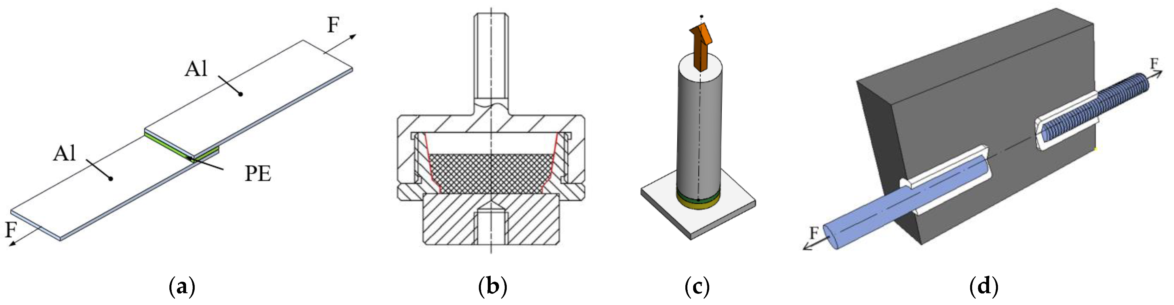
- Lap-shear test (Figure 1a):Originally, it is a standard for testing of adhesives in a shear mode (the loading force is parallel to the joint surface) [23]. In the modified version, it was used in studies investigating adhesion in direct joints in different systems [24,25,26]. Generally, preparation of samples is fast and cheap. The layer of adhesive can be replaced by the investigated polymer. Alternatively, the adhesive layer can be excluded, and one stripe can be made from polymer, creating a two-part assembly with a direct joint. Samples may suffer from warping. In the case of weak tested joint (sample from low-adhesion polymer, e.g., PE), samples can fall apart even with a delicate manipulation. Samples combining high-adhesion polymers (plasma-treated PE) and glass often crack in the glass on their own [15].
- Pull-off test—mold (Figure 1b):The method described in [17,27,28] measures the adhesion in tensile mode (force perpendicular to the joint surface). The disadvantage of this method is an intricate mold assembly used for sample preparation and its testing. As the mold can only be used again after the sample inside is tested, it either increases the demand on their number or decreases the test efficiency. Furthermore, samples from low-adhesion polymers can get spoiled easily without delicate manipulation.
- Pull-off test—dolly (Figure 1c):The ISO EN 4624 [29] tests the adhesion in tensile mode (perpendicular to the joint plane) and is commonly used for paints. The same principle was used for adhesion tests in other systems [30,31]. When used for powders, preparation of the samples consists of many steps and is time-consuming. Polymer powder molten onto a substrate in a thin layer substitutes paint. As in the methods described above, samples from low-adhesion polymers are unstable. On top of that, the testing assembly has more members in the loading chain. Therefore, there are more interfaces where complete or partial failure can occur, which cannot be controlled and can compromise the results.
- Pull-out test (Figure 1d):The method mentioned in [32,33] has a simple mold and is designed to overcome the fragility of samples made from low-adhesion polymers. It makes possible to compare different treatments for improved adhesion with nontreated materials. The interface of interest is between the plastic part and a smooth rod. However, the samples can fail on the side of the threaded rod, because the polymer powder does not properly fill the thread grooves, compromising the reliability of this test.
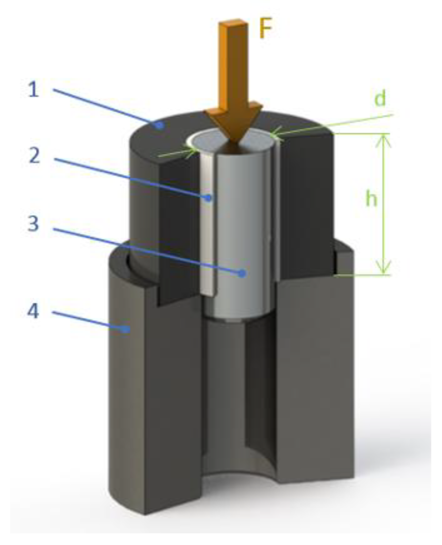
2. The New Testing Method
- Sample plastic parts can be made from polymer powder;
- The possibility to incorporate more plastic layers;
- The method can measure a joint strength in axial shear mode;
- No risk of sample warping;
- Samples must be stable and durable even with low-adhesion polymers;
- Possibility to evaluate adhesion effects visually;
- Comparison of various treatment conditions of polymer powders;
- Comparison of various substrates and their surface properties.
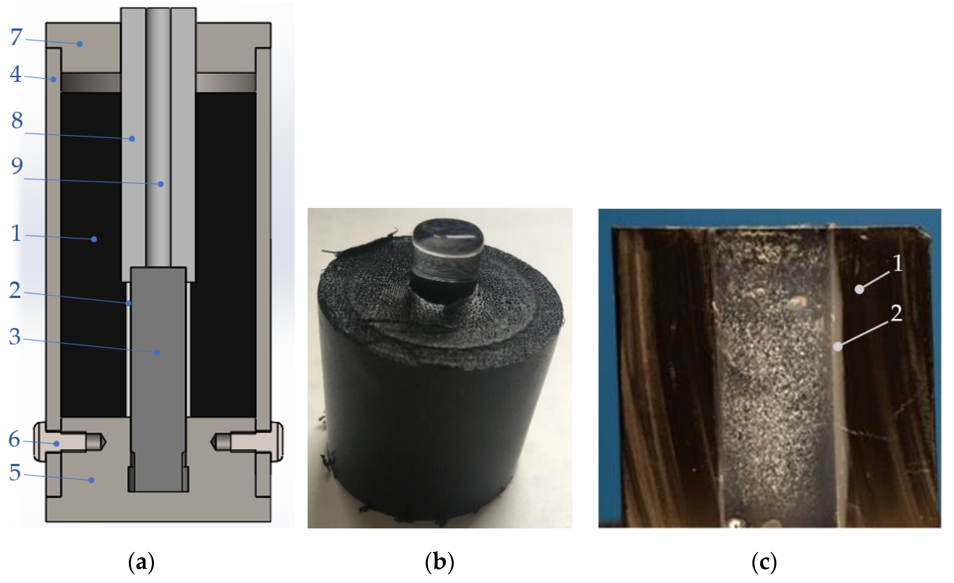
- A leaned substrate (see Figure 3a,b) is heated to a certain temperature to accumulate heat. The temperature depends on the specific material (heat capacity and heat conductivity).
- A hot substrate is immersed in a polymer powder (dip coating), heat from the substrate melts the powder close to the surface (approximately 1–2 mm), the powder adheres to the substrate.
- Assembled molds are filled with extra powder to form the collar of the final sample.
- Molds are placed in a heating chamber for final sintering.
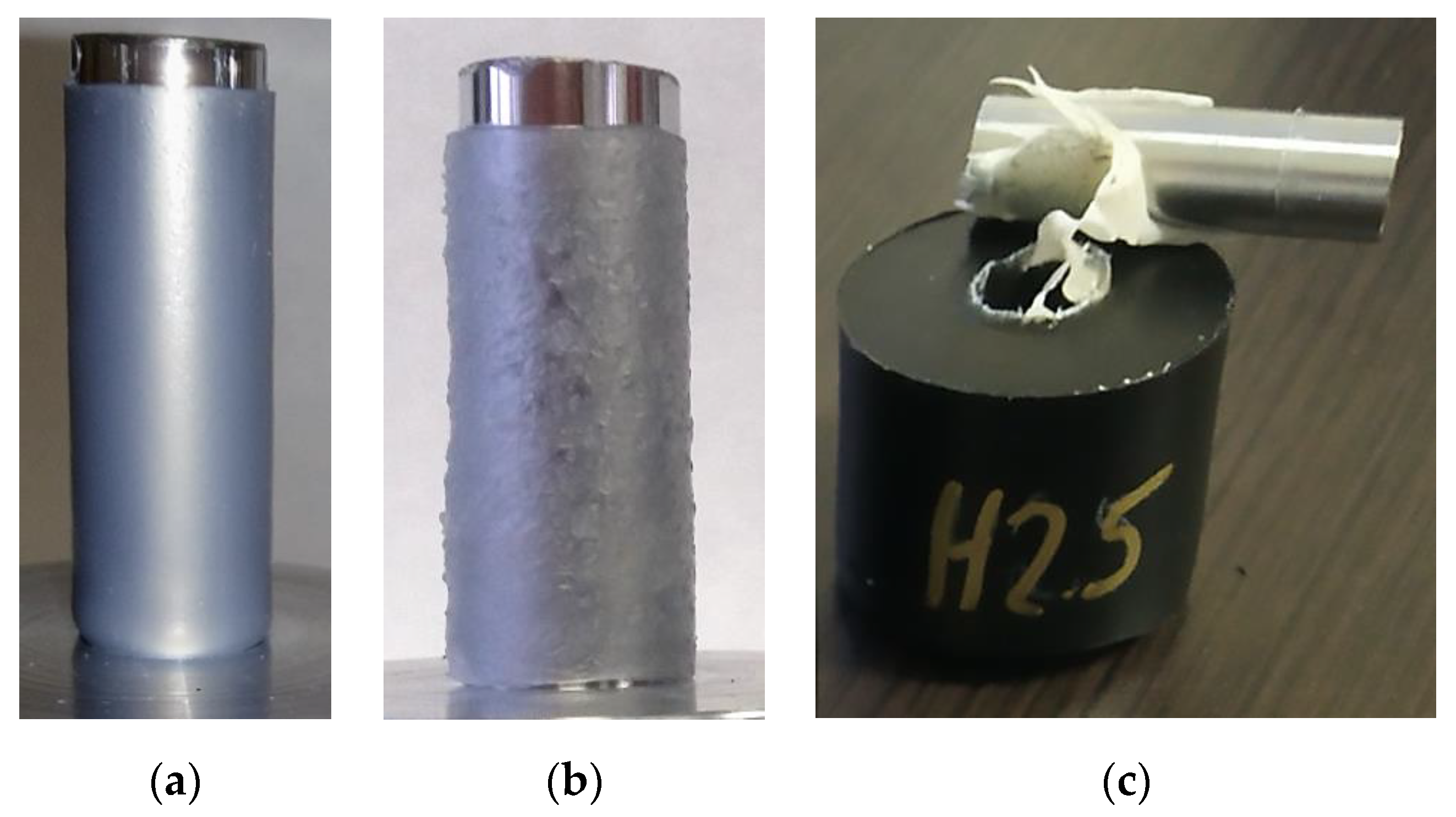
- After cooling down, samples are removed from the molds and ready for testing (Figure 4b).
- For visual examination after the strength test, plastic collars are cut in half to expose the inner diameter (Figure 4c).
3. Materials and Methods
3.1. Materials Characterization
3.2. Plasma Treatment
3.3. Mechanical Testing
3.4. Wettability and Surface Characterization
4. Results and Discussion
4.1. Pin-Collar Strength Test
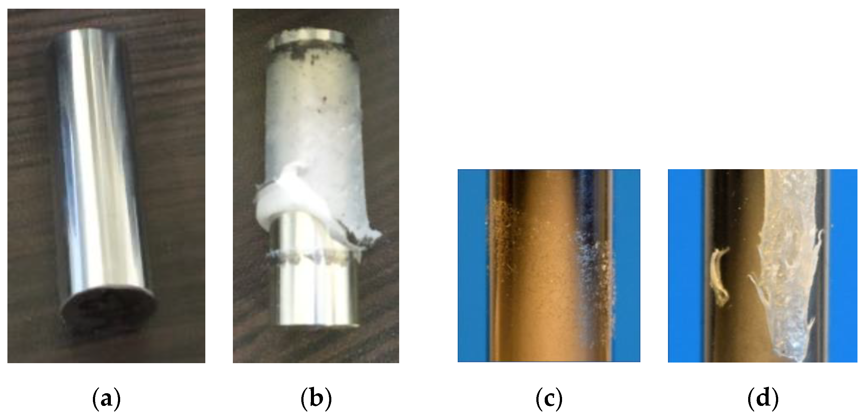
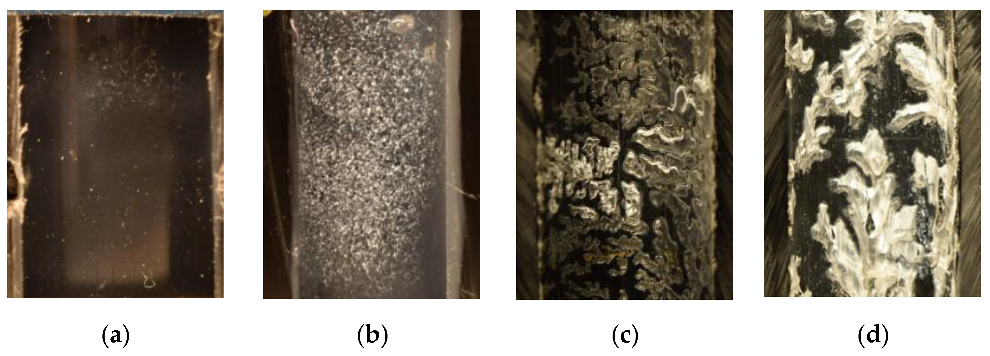
4.1.1. Metal Substrate
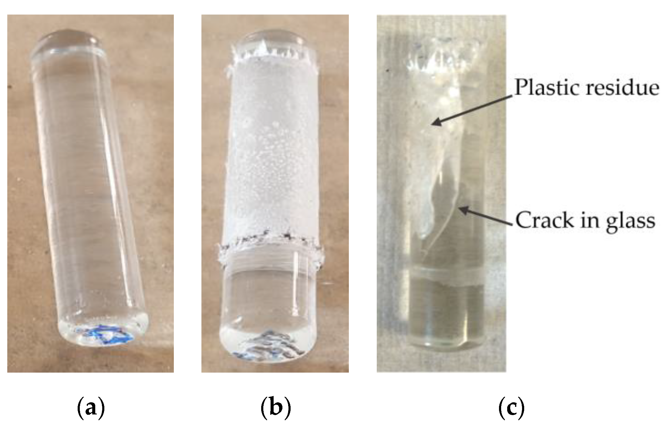
4.1.2. Glass Substrate
4.1.3. Plastic Collar
- Both plastic layers fused well together so they formed a compact piece without any air gaps in-between the layers. The joint failed at the substrate–polymer interface either due to low adhesion or abrupt fracture that did not allow plastic deformation (Figure 7a);
- Both plastic layers fused well together. Areas of plastic are torn or deformed thanks to the good adhesion between the treated polymer and a substrate, which was higher than the strength of the plastic (Figure 7b);
- Formation of air pockets between the plastic layer and the collar caused by their poor fusion. The joint failed at the polymer–substrate interface due to its low adhesion (Figure 7c);
- Formation of air pockets, which are then torn or deformed thanks to the good adhesion between the polymer and a substrate, which was higher than the strength of the plastic (Figure 7d).
4.2. The Effect of Sintering on a Joint Strength
4.3. Optimalization of Plasma Treatment
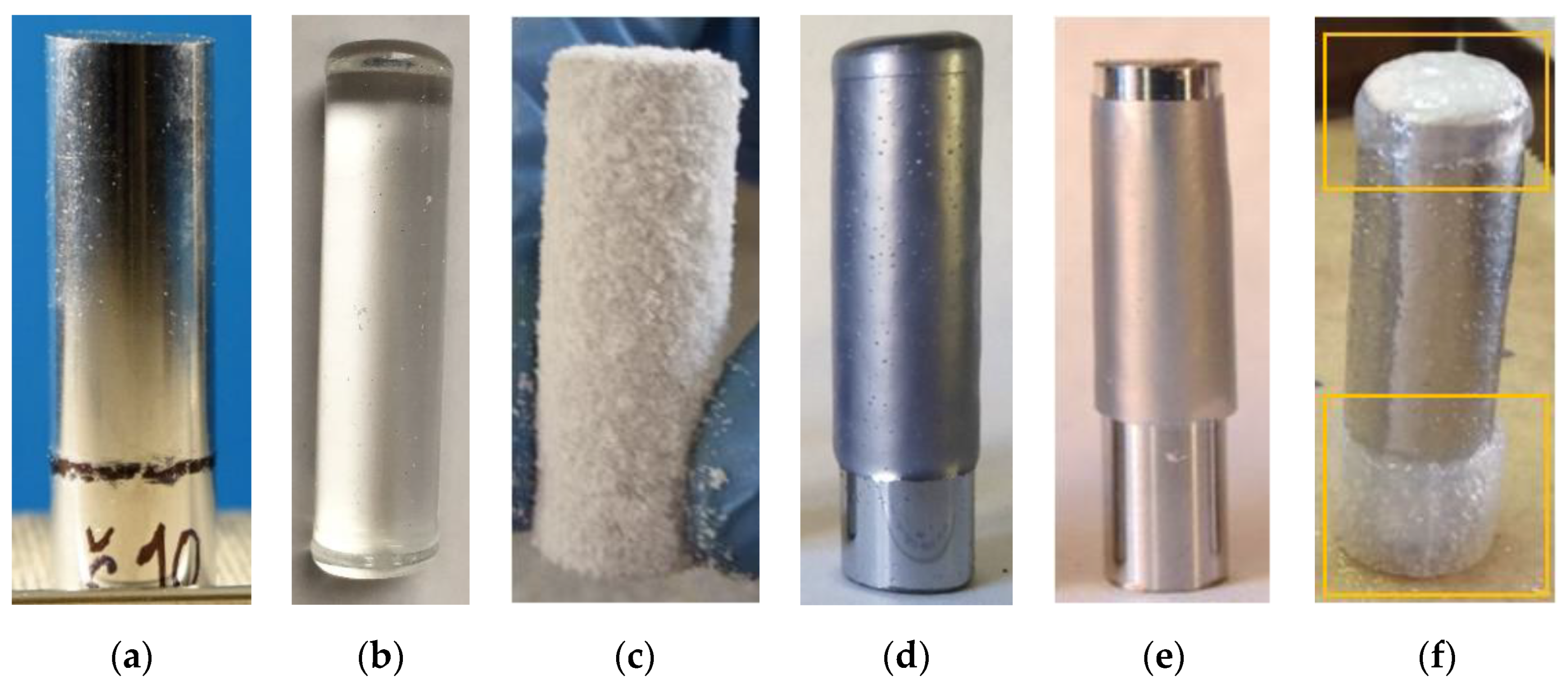
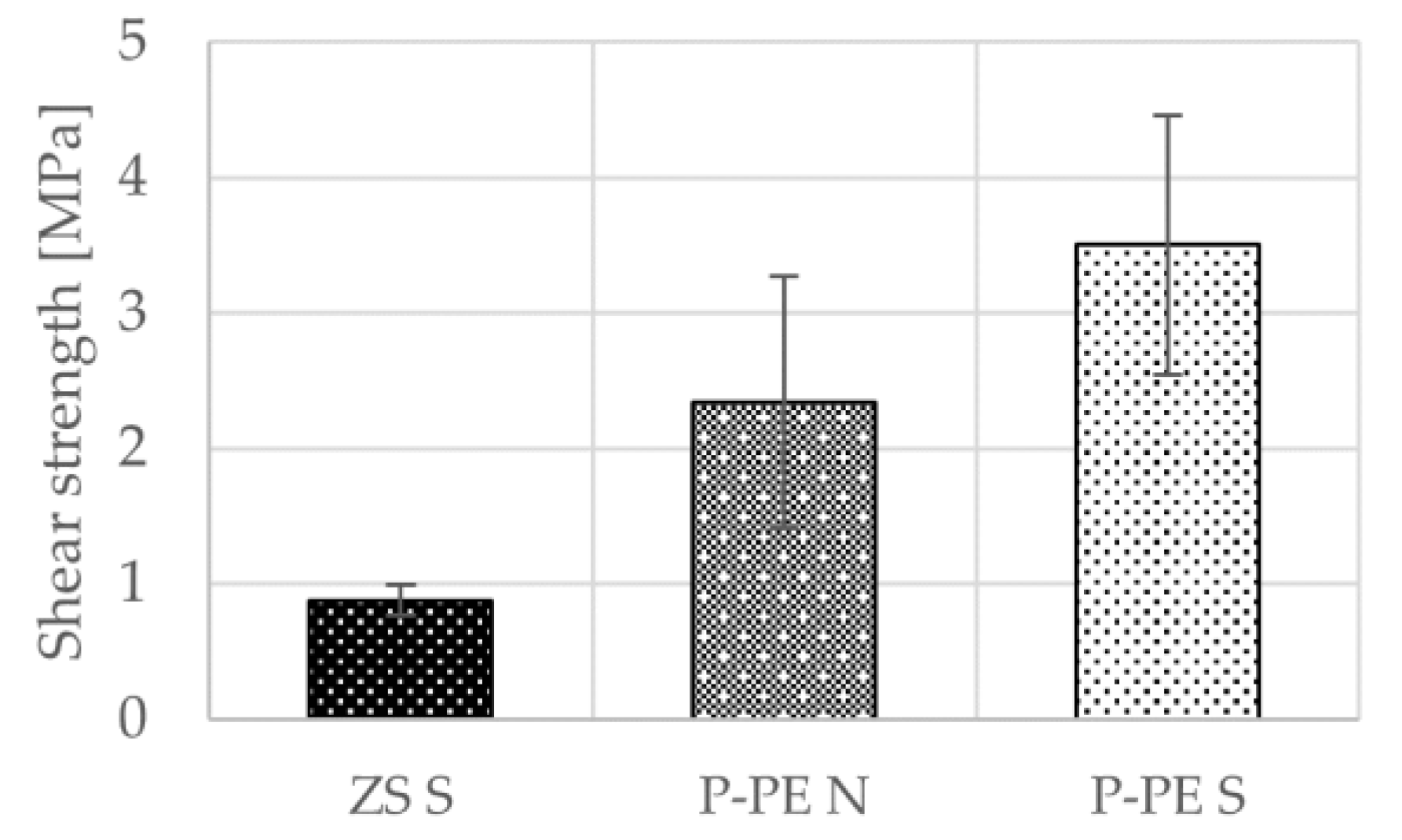
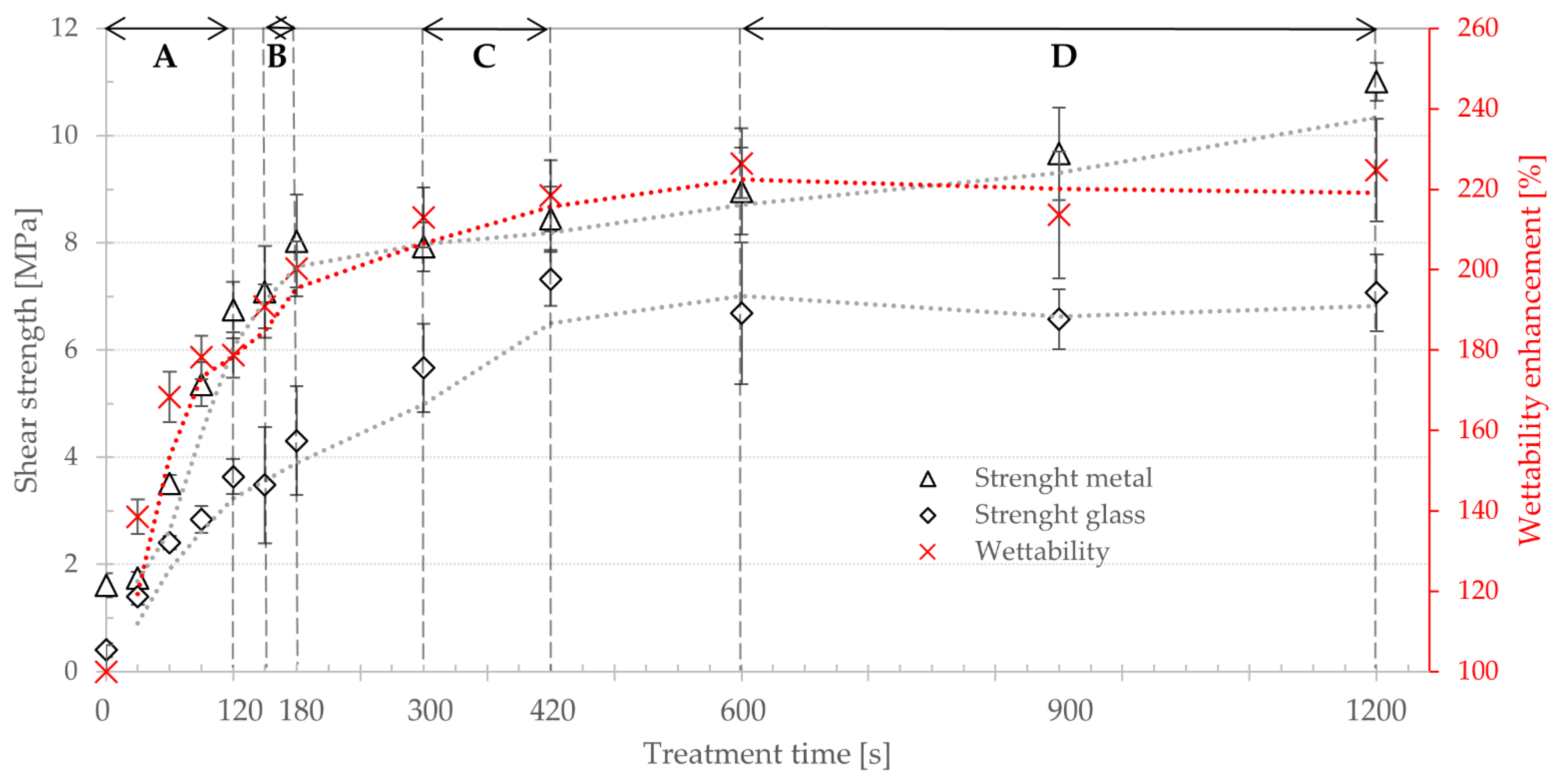
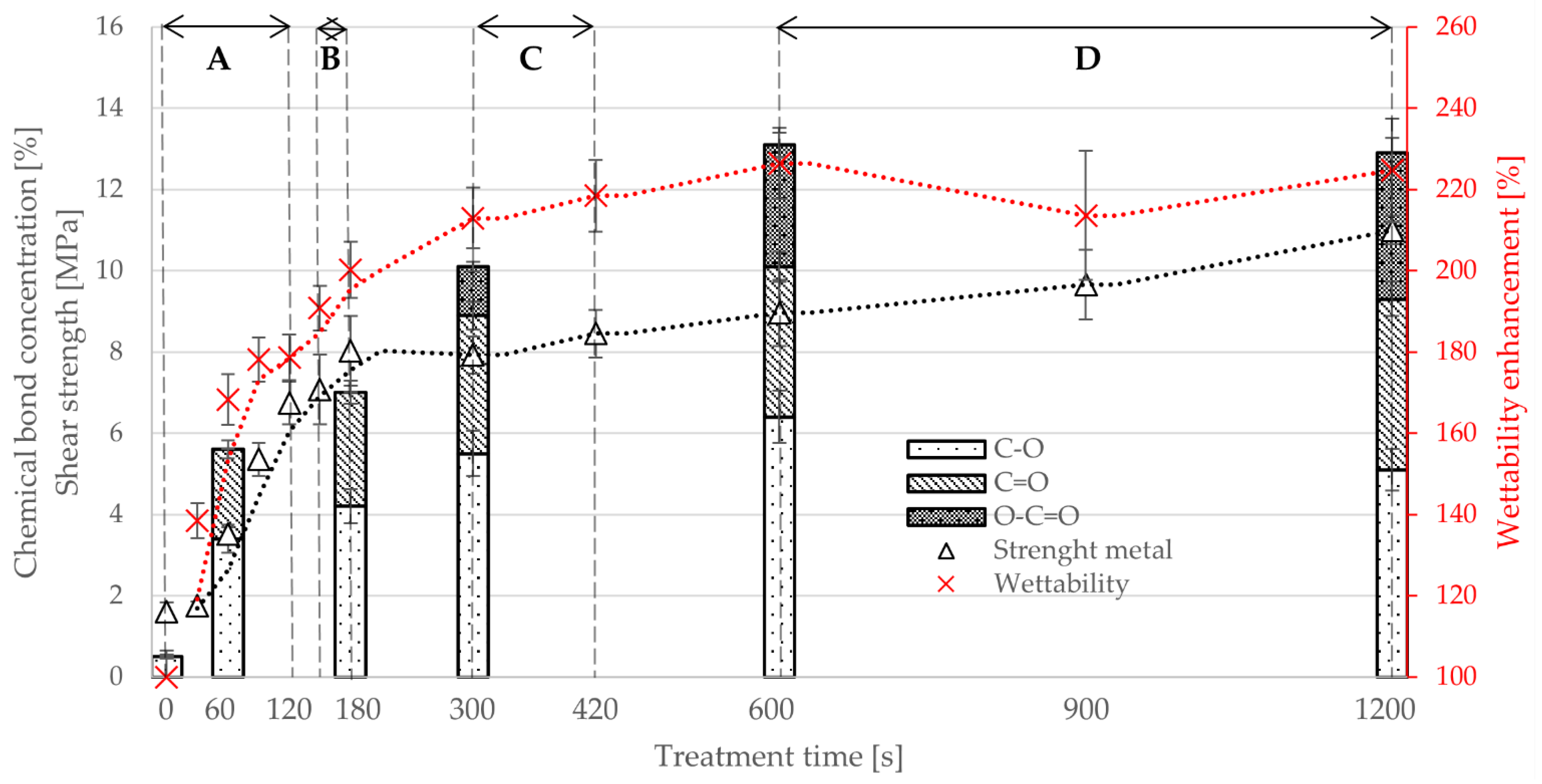
- Area A—short treatment times:Sintering properties of nontreated and treated powders were identical. Sintering of plastic layer required 20 min, and the final layer was smooth and even as in Figure 11a. All samples failed at substrate–polymer interface, substrates after the test look similar to Figure 5a and Figure 6a. The wettability increases rapidly from 100% (ZS) to 179% after 120 s of plasma treatment. The surface concentration of functional groups (C–O and C=O) shows rapid increase from 0.5% of C–O (ZS) to 3.4% (60 s plasma treated) and from 0% of C=O (ZS) to 2.2% (60 s (plasma treatment), respectively. Joint strength on metal showed increase from 1.6 MPa (ZS) to 6.7 MPa (120 s plasma treatment) and on glass from 0.4 MPa (ZS) to 3.6 MPa (120 s plasma treatment).
- Area B—medium treatment times:First changes in behavior of powders and samples. Moderate increase in sintering time to 30 min, final plastic layer is still smooth and even. The joint failures at polymer–substrate interface or in plasma-treated layer (Figure 5c,d). Moderate enhancement of the joint strength was observed: on metal from 7.1 MPa (150 s plasma treatment) to 8.0 MPa (180 s plasma treatment) and on glass from 3.5 MPa (150 s plasma treatment) to 4.3 MPa (180 s plasma treatment). Wettability was increased from 190% to 200% between 150 s and 180 s of the plasma treatment, and the concentration of the functional groups (C–O and C=O) showed moderate increase too on values 4.2% surface concentration of C–O and 2.8% of C=O.
- Area C—long treatment times:Significant increase in sintering time to 45 min. Final plastic layer may show surface irregularities and first changes of failure patterns were observed—exceptional local failure between investigated polymer and plastic collar (Figure 11c). The adhesion slowly increased from 7.9 MPa (300 s plasma treatment) to 8.6 MPa (420 s plasma treatment) on metal and from 5.7 MPa (300 s plasma treatment) to 7.3 MPa (420 s plasma treatment) on glass. The wettability slowly rose from 213% to 218% between 300 s and 420 s plasma treatment. The concentration of functional groups increased to 5.5% (C–O) and 3.4% (C=O), and new O–C=O groups (1.2%) were created.
- Area D—extremely long treatment times:Powder sintering was difficult and requires 60 min. The final surface has a grainy structure (see Figure 11b). Glass substrate often cracked before the rod was pushed out of the collar (Figure 6c) or the joint failed between plastic layer and collar (Figure 6b). Joints with metal substrate commonly failed between plastic layer and collar, either partially or fully (Figure 5b, Figure 6b, Figure 11c). No significant enhancement of the joint strength was observed—between 600 and 1200 s of plasma treatment resulted in joint strength between 9.0 and 11.0 MPa on meta and 6.7 to 7.1 MPa on glass. Saturation of wettability was observed at the values of about 225%. Probably transformation of C–O → C=O → O–C=O chemical groups caused lowering concentration of C–O (6.4% to 5.1%) and increasing of C=O (3.7% to 4.2%) and O–C=O groups (3.0% to 3.6%) between 600 and 1200 s of plasma treatment. Treatment time of 1200 s is approaching the limits of this type of plasma treatment and has a low application potential. Temperature of treated powder was nearly 50 °C and, therefore, continuous production without additional external cooling of the treatment chamber and mixing pot is not possible.
5. Conclusions
- Adhesion to both substrates corelates with wettability enhancement and concentration of oxygen groups on powder surface;
- Adhesion to metal substrate increased from 1.6 MPa (nontreated powder) to 11.0 MPa (plasma treatment 1200 s) and to glass substrate from 0.4 MPa (nontreated powder) to 7.1 MPa (plasma treatment 1200 s);
- Although melt flow index is unchanged by plasma treatment, the method revealed different sintering properties of powders treated for different times. Powder treated for 120 s was sintered after 20 min, powder treated for 1200 s after 60 min;
- Powders treated for 300 s or longer have decreased ability to bind with another powder (sample failure at plastic–plastic interface). Samples with lower treatment times form compact mass with another powder upon sintering;
- The new method is suitable for further research in optimization of plasma treatment of polymer powders for composite materials and other applications utilizing direct joints of polymers and dissimilar materials.
Supplementary Materials
Author Contributions
Funding
Conflicts of Interest
References
- Hancox, N.L. Engineering mechanics of composite materials. Mater. Des. 1996, 17, 114. [Google Scholar] [CrossRef]
- Rajak, D.K.; Pagar, D.D.; Menezes, P.L.; Linul, E. Fiber-reinforced polymer composites: Manufacturing, properties, and applications. Polymers 2019, 11, 1667. [Google Scholar] [CrossRef]
- Sherif, G.; Chukov, D.; Tcherdyntsev, V.; Torokhov, V. Effect of formation route on the mechanical properties of the polyethersulfone composites reinforced with glass fibers. Polymers 2019, 11, 1364. [Google Scholar] [CrossRef] [PubMed]
- Sezemský, J.; Špatenka, P. Adhesion improvement between pe and pa in multilayer rotational molding. Polymers 2021, 13, 331. [Google Scholar] [CrossRef]
- Hanana, F.E.; Chimeni, D.Y.; Rodrigue, D. Morphology and mechanical properties of maple reinforced LLDPE produced by rotational moulding: Effect of fibre content and surface treatment. Polym. Polym. Compos. 2018, 26, 299–308. [Google Scholar] [CrossRef]
- León, L.D.V.E.; Escocio, V.A.; Visconte, L.L.Y.; Junior, J.C.J.; Pacheco, E.B.A.V. Rotomolding and polyethylene composites with rotomolded lignocellulosic materials: A review. J. Reinf. Plast. Compos. 2020, 39, 459–472. [Google Scholar] [CrossRef]
- Cisneros-López, E.O.; González-López, M.E.; Pérez-Fonseca, A.A.; González-Núñez, R.; Rodrigue, D.; Robledo-Ortíz, J.R. Effect of fiber content and surface treatment on the mechanical properties of natural fiber composites produced by rotomolding. Compos. Interfaces 2017, 24, 35–53. [Google Scholar] [CrossRef]
- Höfler, G.; Jayaraman, K.; Lin, R. Rotational moulding and mechanical characterisation of micron-sized and nano-sized reinforced high density polyethylene. In Key Engineering Materials; Trans Tech Publications Ltd.: Baech, Switzerland, 2019; Volume 809, pp. 65–70. [Google Scholar] [CrossRef]
- Wei, H.; Xia, J.; Zhou, W.; Zhou, L.; Hussain, G.; Li, Q.; Ostrikov, K.K. Adhesion and cohesion of epoxy-based industrial composite coatings. Compos. Part B Eng. 2020, 193, 108035. [Google Scholar] [CrossRef]
- Pereira, P.H.F.; De Rosa, M.F.; Cioffi, M.O.H.; De Benini, K.C.C.C.; Milanese, A.C.; Voorwald, H.J.C.; Mulinari, D.R. Vegetal fibers in polymeric composites: A review. Polimeros 2015, 25, 9–22. [Google Scholar] [CrossRef]
- Barczewski, M.; Szostak, M.; Nowak, D.; Piasecki, A. Effect of wood flour addition and modification of its surface on the properties of rotationally molded polypropylene composites. Polimery 2018, 63, 772–784. [Google Scholar] [CrossRef]
- Li, R.; Ye, L.; Mai, Y.W. Application of plasma technologies in fibre-reinforced polymer composites: A review of recent developments. Compos. Part A Appl. Sci. Manuf. 1997, 28, 73–86. [Google Scholar] [CrossRef]
- Arpagaus, C.; Oberbossel, G.; von Rohr, P.R. Plasma treatment of polymer powders-from laboratory research to industrial application. Plasma Process Polym. 2018, 15, 1800133. [Google Scholar] [CrossRef]
- SurfaceTreat-About Company. Available online: http://surfacetreat.cz/en/about-company/ (accessed on 20 February 2021).
- Novacek, V.; Vackova, T.; Spatenka, P.; Jenikova, Z. Application of low temperature plasma treatment for thermoplastic composites. In Proceedings-2017 International Conference on Optimization of Electrical and Electronic Equipment, Proceedings of the OPTIM 2017 and 2017 Intl Aegean Conference on Electrical Machines and Power Electronics, ACEMP 2017, Brasov, Romania, 2–4 September 2017; Institute of Electrical and Electronics Engineers Inc.: New York, NY, USA, 2017; pp. 1027–1032. [Google Scholar] [CrossRef]
- Sari, P.S.; Thomas, S.; Spatenka, P.; Ghanem, Z.; Jenikova, Z. Effect of plasma modification of polyethylene on natural fibre composites prepared via rotational moulding. Compos. Part B Eng. 2019, 177, 107344. [Google Scholar] [CrossRef]
- Horakova, M.; Spatenka, P.; Hladik, J.; Hornik, J.; Steidl, J.; Polachova, A. Investigation of Adhesion Between Metal and Plasma-Modified Polyethylene. Plasma Process. Polym. 2011, 8, 983–988. [Google Scholar] [CrossRef]
- Šourková, H.; Špatenka, P. Plasma Activation of Polyethylene Powder. Polymers 2020, 12, 2099. [Google Scholar] [CrossRef] [PubMed]
- Alghunaim, A.; Kirdponpattara, S.; Newby, B.M.Z. Techniques for determining contact angle and wettability of powders. Powder Technol. 2016, 287, 201–215. [Google Scholar] [CrossRef]
- Mozetič, M. Surface Modification to Improve Properties of Materials. Materials 2019, 12, 441. [Google Scholar] [CrossRef]
- Yan, W.; Lin, R.J.T.; Bhattacharyya, D. Particulate reinforced rotationally moulded polyethylene composites-Mixing methods and mechanical properties. Compos. Sci. Technol. 2006, 66, 2080–2088. [Google Scholar] [CrossRef]
- Crawford, R.J.; Kearns, M.P. Practical Guide to Rotational Moulding, 2nd ed.; Smithers Rapra: Shropshire, UK, 2012; ISBN 9781847355119. [Google Scholar]
- ISO. Adhesives-Determination of tensile lap-shear strength of bonded assemblies (DIN EN 1465:2009-07). Int. Stand. ISO 2009, 11, 778–794. [Google Scholar]
- Scarselli, G.; Quan, D.; Murphy, N.; Deegan, B.; Dowling, D.; Ivankovic, A. Adhesion Improvement of Thermoplastics-Based Composites by Atmospheric Plasma and UV Treatments. Appl. Compos. Mater. 2021, 28, 71–89. [Google Scholar] [CrossRef]
- Kajihara, Y.; Tamura, Y.; Kimura, F.; Suzuki, G.; Nakura, N.; Yamaguchi, E. Joining strength dependence on molding conditions and surface textures in blast-assisted metal-polymer direct joining. CIRP Ann. 2018, 67, 591–594. [Google Scholar] [CrossRef]
- Ülker, A.; Ayaz, A. Optimization of process parameters of friction stir spot welding of polycarbonate sheets and morphological analysis. Materwiss Werksttech. 2020, 51, 1640–1652. [Google Scholar] [CrossRef]
- Hladik, J.; Spatenka, P.; Aubrecht, L.; Pichal, J. New method of microwave plasma treatment of HDPE powders. Czechoslov. J. Phys. 2006, 56, B1120–B1125. [Google Scholar] [CrossRef]
- Hladík, J. Aplikace Plazmových Technologií Pro Úpravy a Zušlechťování Povrchů Práškových Hmot. Master’s Thesis, Technical University of Liberec, Liberec, Czech Republic, 2007. [Google Scholar]
- ISO. Paints and varnishes-Pull-off test for adhesion (ISO 4624:2002). Int. Stand. ISO 2002, 20, 4624. [Google Scholar]
- Barroso, G.; Döring, M.; Horcher, A.; Kienzle, A.; Motz, G. Polysilazane-Based Coatings with Anti-Adherent Properties for Easy Release of Plastics and Composites from Metal Molds. Adv. Mater. Interfaces 2020, 7, 1901952. [Google Scholar] [CrossRef]
- Brinkhues, S.; Kanthamneni, A.; Brose, A.; Majcherek, S.; Schmidt, B. Investigation of adhesion strength of metallization on thermoplastic and ceramic substrates. In Proceedings of the 2016 12th International Congress Molded Interconnect Devices-Scientific Proceedings, MID 2016, Würzburg, Germany, 28–29 September 2016. [Google Scholar] [CrossRef]
- Weberová, Z. Low-Pressure Cold Plasma Surface Treatment for Adhesion Improvement in Composite Structures. In Proceedings of the Annual Technical Conference Proceedings, Long Beach, CA, USA, 27 April–2 May 2019; Society of Vacuum Coaters: Albuquerque, Mexico, 2019; pp. 43–50. [Google Scholar] [CrossRef]
- Weberová, Z. Evaluation of Adhesion in Metal-Plastic Welded Joints. Master’s Thesis, Czech Technical University, Prague, Czech Republic, 2019. [Google Scholar]
- ISO. Adhesives-Determination of shear strength of anaerobic adhesives using pin-and-collar specimens (ISO 10123:1990 modified). Int. Stand. ISO 2009, 11, 15. [Google Scholar]
- Dow Chemical Company Technical Information: DowlexTM 2629UE Polyethylene Resin. Available online: https://www.dow.com/content/dam/dcc/documents/en-us/productdatasheet/400/400-00089043en-dowlex-2629ue-tds.pdf (accessed on 21 February 2021).
- LyondellBasell Industries Technical Information: ICORENE® 1613 BK85. Available online: https://plastics.ulprospector.com/datasheet/e139923/icorene-1613-bk85 (accessed on 21 February 2021).
- ISO. Plastics—Determination of the melt mass-flow rate (MFR) and the melt volume-flow rate (MVR) of thermoplastics (ISO 1133:2005). Int. Stand. ISO 2005, 1–12. [Google Scholar]
- Šourková, H.; Primc, G.; Špatenka, P. Surface functionalization of polyethylene granules by treatment with low-pressure air plasma. Materials 2018, 11, 885. [Google Scholar] [CrossRef] [PubMed]
- Washburn, E.W. The dynamics of capillary flow. Phys. Rev. 1921, 17, 273–283. [Google Scholar] [CrossRef]
- Pandiyaraj, K.N.; Deshmukh, R.R.; Ruzybayev, I.; Shah, S.I.; Su, P.G.; Halleluyah, M.; Halim, A.S. Influence of non-thermal plasma forming gases on improvement of surface properties of low density polyethylene (LDPE). Appl. Surf. Sci. 2014, 307, 109–119. [Google Scholar] [CrossRef]
- Jin, S.Y.; Manuel, J.; Zhao, X.; Park, W.H.; Ahn, J.H. Surface-modified polyethylene separator via oxygen plasma treatment for lithium ion battery. J. Ind. Eng. Chem. 2017, 45, 15–21. [Google Scholar] [CrossRef]
- Abusrafa, A.E.; Habib, S.; Krupa, I.; Ouederni, M.; Popelka, A. Modification of polyethylene by RF plasma in different/mixture gases. Coatings 2019, 9, 145. [Google Scholar] [CrossRef]
- Yasuda, H.; Lamaze, C.E.; Sakaoku, K. Effect of electrodeless glow discharge on polymers. J. Appl. Polym. Sci. 1973, 17, 137–152. [Google Scholar] [CrossRef]
- Nandi, S.; Winter, H.H. Swelling behavior of partially cross-linked polymers: A ternary system. Macromolecules 2005, 38, 4447–4455. [Google Scholar] [CrossRef]
- Chang, S.; Kim, M.; Oh, S.; Min, J.H.; Kang, D.; Han, C.; Ahn, T.; Koh, W.G.; Lee, H. Multi-scale characterization of surface-crosslinked superabsorbent polymer hydrogel spheres. Polymer 2018, 145, 174–183. [Google Scholar] [CrossRef]
- Kiran, E.; Zhuang, W. Solubility of polyethylene in n-pentane at high pressures. Polymer 1992, 33, 5259–5263. [Google Scholar] [CrossRef]
- Ghanem, Z.; Sasidharan, S.P.; Jenikova, Z.; Špatenka, P. Rotational molding of plasma treated polyethylene/short glass fiber composites. Int. J. Eng. Manag. Sci. 2019, 4, 103–108. [Google Scholar] [CrossRef]


| Area | Treatment Time (s) | Sintering Time (min) |
|---|---|---|
| A | 0–120 | 20 |
| B | 150–180 | 30 |
| C | 300–420 | 45 |
| D | 600–1200 | 60 |
| Treatment Gas | Treatment Time (s) | MFI (g/10 min) |
|---|---|---|
| No treatment | 0 | 5.1 |
| Oxygen | 30 | 4.9 |
| 150 | 5.2 | |
| 300 | 4.9 | |
| 600 | 4.9 |
Publisher’s Note: MDPI stays neutral with regard to jurisdictional claims in published maps and institutional affiliations. |
© 2021 by the authors. Licensee MDPI, Basel, Switzerland. This article is an open access article distributed under the terms and conditions of the Creative Commons Attribution (CC BY) license (http://creativecommons.org/licenses/by/4.0/).
Share and Cite
Weberová, Z.; Šourková, H.; Antoň, J.; Vacková, T.; Špatenka, P. New Method for Optimization of Polymer Powder Plasma Treatment for Composite Materials. Polymers 2021, 13, 965. https://doi.org/10.3390/polym13060965
Weberová Z, Šourková H, Antoň J, Vacková T, Špatenka P. New Method for Optimization of Polymer Powder Plasma Treatment for Composite Materials. Polymers. 2021; 13(6):965. https://doi.org/10.3390/polym13060965
Chicago/Turabian StyleWeberová, Zuzana, Hana Šourková, Jakub Antoň, Taťána Vacková, and Petr Špatenka. 2021. "New Method for Optimization of Polymer Powder Plasma Treatment for Composite Materials" Polymers 13, no. 6: 965. https://doi.org/10.3390/polym13060965
APA StyleWeberová, Z., Šourková, H., Antoň, J., Vacková, T., & Špatenka, P. (2021). New Method for Optimization of Polymer Powder Plasma Treatment for Composite Materials. Polymers, 13(6), 965. https://doi.org/10.3390/polym13060965