
Possibility for Replicating Mechanoscopic Surface Marks in the Hybrid Vacuum-Pressure Casting Process


Abstract
:1. Introduction
State of the Art—Vacuum Casting (VC)
2. Aim of Research
3. Materials and Design
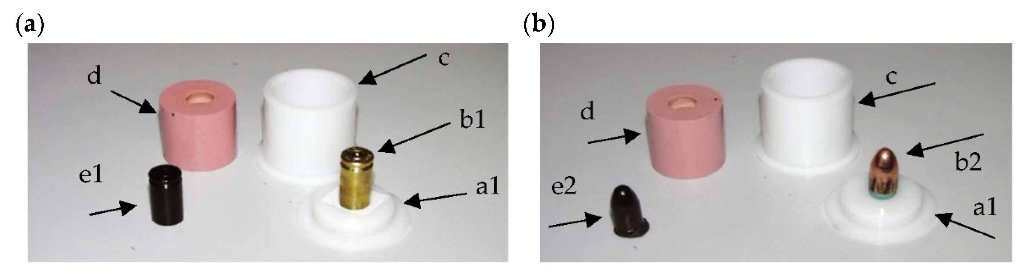
3.1. Mold Making
- Preparation of the master pattern, the gating and feeding system, and the molding box;
- Preparation of the mold material compounds (two compounds of silicone rubber);
- Casting of the mold (encapsulation of master pattern with silicone rubber);
- Removal of the master pattern.
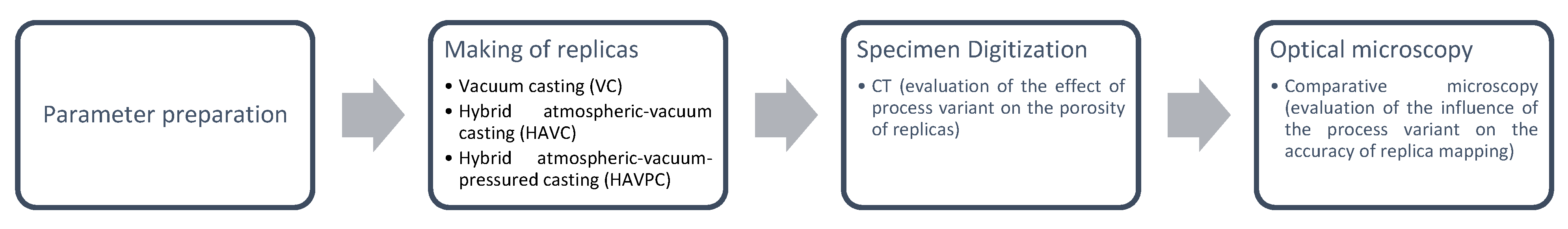
3.2. Part Casting
- Vacuum casting (VC),
- Hybrid atmospheric-vacuum casting (HAVC),
- Hybrid atmospheric-vacuum-pressured casting (HAVPC).
- An atmospheric pressure step, covering both the combination and mixing of the thermosetting polymers, as well as pouring them in the mold;
- A vacuum step, during which the thermosetting polymer poured into the mold is briefly degassed;
- A polymerization step, performed at atmospheric pressure and at ambient temperature or at an elevated temperature in order to shorten the curing time.
- An atmospheric step, covering both the combination and mixing of the thermosetting polymers, as well as pouring them in the mold;
- A vacuum step, covering preliminary degasification by removing/closing the pores and their transfer to the near-surface area;
- A pressure step, provided in order to reduce and remove all of the near-surface pores;
- A polymerization step performed at atmospheric pressure and, as in HVAC, at an ambient or elevated temperature.
3.3. Post-Processing
- A KLM V400 A vacuum chamber for producing the molds and replicating the master patterns,
- A POL-EKO SLM 15 STD stove for preparing the molds and the cast parts,
- A pressure chamber for further treatment of the cast parts,
- A Sputter Coater 7620 machine for sputtering the PVD coatings.
4. Results and Discussion
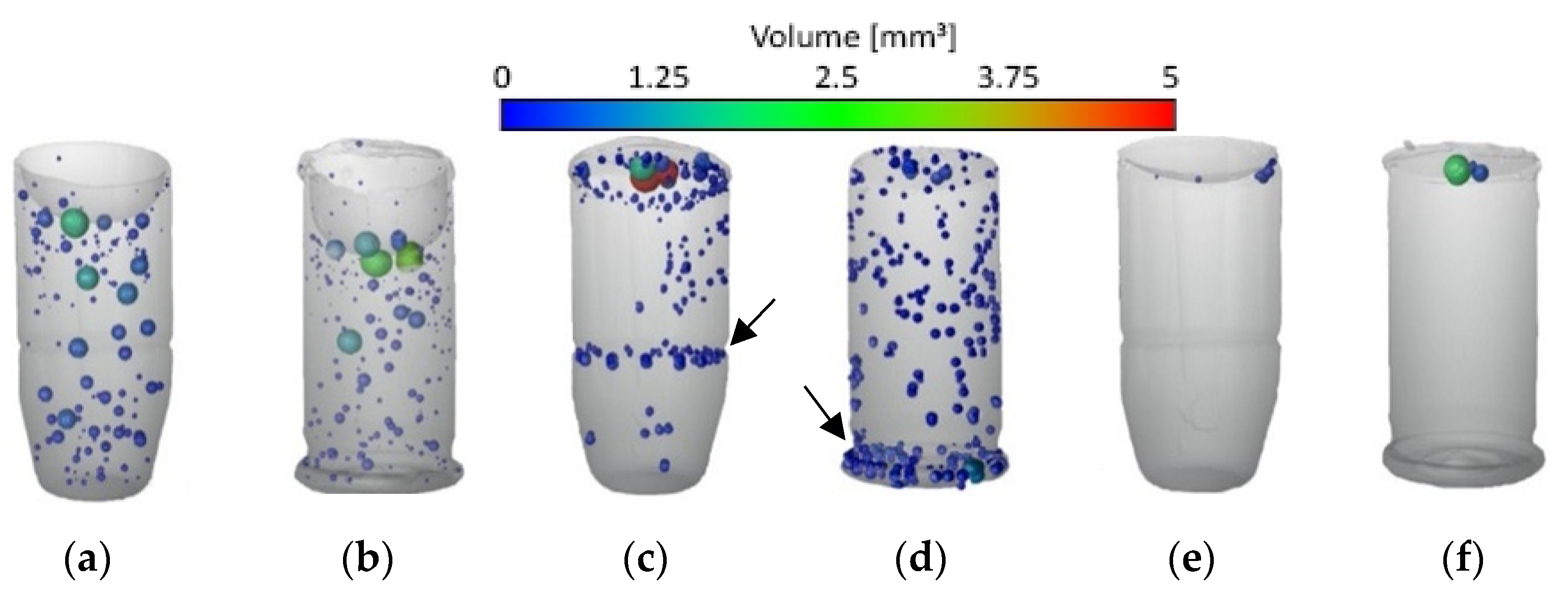
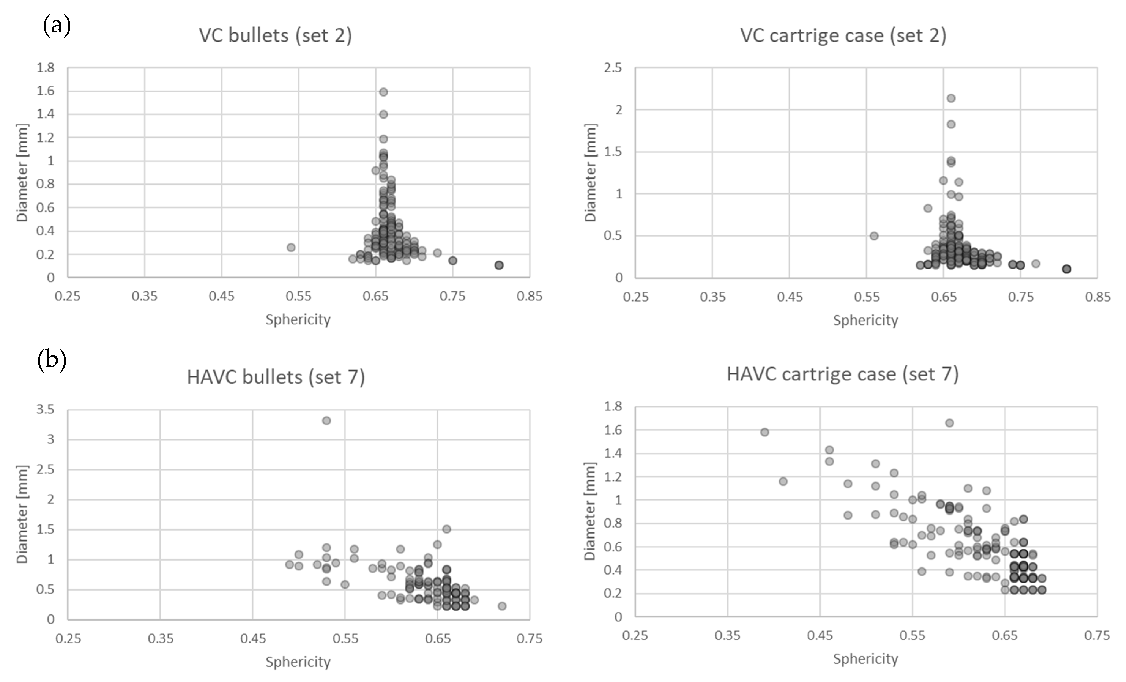
4.1. Assessment by Industrial Computed Tomography (CT)
4.2. Analysis of the Accuracy of Geometric Reproduction
5. Conclusions
Author Contributions
Funding
Institutional Review Board Statement
Informed Consent Statement
Data Availability Statement
Conflicts of Interest
References
- Male, J.; Tsang, H.; Bennett, G. A Time, Cost and Accuracy Comparison of Soft Tooling for Investment Casting Produced Using Stereolithography Techniques. In Proceedings of the 1996 International Solid Freeform Fabrication Symposium, Austin, TX, USA, 12–14 August 1996; pp. 1–8. [Google Scholar]
- Kuo, C.C.; Wu, M.H.; Lai, M.Y. Development of a Low-Cost Automatic Vacuum Degassing System for Rapid Tooling. Appl. Mech. Mater. 2013, 459, 349–355. [Google Scholar] [CrossRef]
- Kuo, C.-C.; Wu, M.-X. Evaluation of service life of silicone rubber molds using vacuum casting. Int. J. Adv. Manuf. Technol. 2017, 90, 3775–3781. [Google Scholar] [CrossRef]
- Kuo, C.-C.; Chen, W.-H.; Lin, Y.-X.; Gao, Q.; Gian, S.-J.; Xiao, C.-X. Effects of different fillers on the silicone rubber mold with conformal cooling channels. Int. J. Adv. Manuf. Technol. 2020, 108, 1509–1525. [Google Scholar] [CrossRef]
- Tang, Y.; Tan, W.; Fuh, J.; Loh, H.; Wong, Y.; Thian, S.; Lu, L. Micro-mould fabrication for a micro-gear via vacuum casting. J. Mater. Process. Technol. 2007, 192–193, 334–339. [Google Scholar] [CrossRef]
- Ramos, A.; Relvas, C.; Simes, J. Vacuum casting with room temperature vulcanising rubber and aluminium moulds for rapid manufacturing of quality parts: A comparative study. Rapid Prototyp. J. 2003, 9, 111–115. [Google Scholar] [CrossRef]
- Hansen, H.N.; Hocken, R.; Tosello, G. Replication of micro and nano surface geometries. CIRP Ann. Manuf. Technol. 2011, 60, 695–714. [Google Scholar] [CrossRef]
- Zhao, D.-Y.; Huang, Z.-P.; Wang, M.-J.; Wang, T.; Jin, Y. Vacuum casting replication of micro-riblets on shark skin for drag-reducing applications. J. Mater. Process. Technol. 2012, 212, 198–202. [Google Scholar] [CrossRef]
- Denoual, M.; Macé, Y.; Le Pioufle, B.; Mognol, P.; Castel, D.; Gidrol, X. Vacuum casting to manufacture a plastic biochip for highly parallel cell transfection. Meas. Sci. Technol. 2006, 17, 3134–3140. [Google Scholar] [CrossRef]
- Desmet, L.; Van Overmeire, S.; Van Erps, J.; Ottevaere, H.; Debaes, C.; Thienpont, H. Elastomeric inverse moulding and vacuum casting process characterization for the fabrication of arrays of concave refractive microlenses. J. Micromech. Microeng. 2007, 17, 81–88. [Google Scholar] [CrossRef]
- De Monteiro Ramos, A.M.; Simes, J.A. CAD-CAM-RTV—Lost-wax casting technology for medical implants. Rapid Prototyp. J. 2009, 15, 211–215. [Google Scholar] [CrossRef]
- Song, M.S.; Choi, H.Y.; Seong, J.H.; Kim, E.S. Matching-index-of-refraction of transparent 3D printing models for flow visualization. Nucl. Eng. Des. 2015, 284, 185–191. [Google Scholar] [CrossRef]
- Frankiewicz, M.; Będza, T.; Dybała, B. Accuracy issues in indirect rapid tooling processes. In Proceedings of the Production Engineering: Innovations and Technologies of the Future; Institute of Production Engineering and Automation: Wroclaw, Poland, 2011; pp. 37–42. [Google Scholar]
- Chlebus, E.; Frankiewicz, M. Rapid Tooling in integrated development of injection moulds. In Proceedings of the International User’s Conference on Rapid Prototyping & Rapid High-Tech Solutions and Best-Practice Concepts. Proceedings; Meyer, E.R., Ed.; Fraunhofer IRB Verlag: Leipzig, Germany, 2005; p. 5. [Google Scholar]
- Chung, S.; Im, Y.; Jeong, H.; Jeong, D.; Cho, K.; Lee, S.; Choi, B.; Choi, H. Rapid fabrication of aluminum shoe mold using vacuum sealed casting process. J. Mater. Process. Technol. 2003, 142, 326–333. [Google Scholar] [CrossRef]
- Ng, W.; Seet, H.; Lee, K.; Ning, N.; Tai, W.; Sutedja, M.; Fuh, J.; Li, X. Micro-spike EEG electrode and the vacuum-casting technology for mass production. J. Mater. Process. Technol. 2009, 209, 4434–4438. [Google Scholar] [CrossRef]


| Silicone | Catalyst | Mix | |
|---|---|---|---|
| Mixing proportion (by weight) | 10 | 1 | |
| Low Temperature Brookfield Viscosity (mPas) | 26,000 | 140 | 13,000 |
| Density at 25 °C (g/cm3) | - | - | 1.12 |
| Working life at 23 °C (for 150 g) | - | - | 105 min |
| Mechanical properties at 23 °C (1) | |||
| Hardness after 24 h | - | Shore A | 61 |
| Elongation at break | - | % | 850 |
| Breaking strength | - | MPa | 7 |
| Tearing strength | - | kN/m | 23 |
| RenLam M-1 | Ren HY 956 (Activator) | Mix | |
|---|---|---|---|
| Mixing proportion (by weight) | 5 | 1 | |
| Form | Liquid | Liquid | Liquid |
| Working life at 25 °C (for 500 g) | 30 min | ||
| Viscosity at 25 °C mPas | 1250–1600 | 370–470 | 1200 |
| Density g/cm3 | 1.1 | 1.0 | 1.1 |
| Series No. | Vacuum Casting | Pressure Casting | Mold Preparation Temperature (°C) | ||||
|---|---|---|---|---|---|---|---|
| Feeding Pressure (mbar) | Degasification Pressure (mbar) | Degasification Time (s) | Pressure (bar) | Time (min) | |||
| VC | 1 | 1 × 10⁻¹ | atm | 90 | - | - | 20 |
| 2 | 1 × 10⁻¹ | 1 × 10⁻¹ | 90 | - | - | 20 | |
| 3 | 1 × 10⁻¹ | 1 × 10⁻¹ | 90 | - | - | 60 | |
| 4 | 1 × 10⁻¹ | 75 | 90 | - | - | 20 | |
| 5 | 1 × 10⁻¹ | 75 | 90 | - | - | 60 | |
| HAVC | 6 | atm | 250 | 90 | - | - | 60 |
| 7 | atm | 500 | 90 | - | - | 60 | |
| 8 | atm | 400 | 120 | - | - | 60 | |
| 9 | atm | 500 | 120 | - | - | 60 | |
| HAVPC | 10 | atm | 400 | 120 | 1 | 165 | 60 |
| 11 | atm | 400 | 120 | 2 | 90 | 60 | |
| 12 | atm | 400 | 120 | 2 | 60 | 60 | |
| 13 | atm | 500 | 120 | 2 | 60 | 60 | |
| Application of PVD Coatings | |
|---|---|
| Current intensity | 18 mA |
| Coating speed | 7.5 nm/1 min |
| Coating thickness | 10 µm |
| Coating (target) material | Au |
| Series No. | Standard Deviation | Confidence Interval | Location of the Pores | ||
|---|---|---|---|---|---|
| Internal | On the Surface Layer | ||||
| 2 | 1.360 | 0.033 | 0.034 | + | + |
| 7 | 1.293 | 0.086 | 0.089 | + | + |
| 13 | 0.097 | 0.097 | 0.054 | + | - |
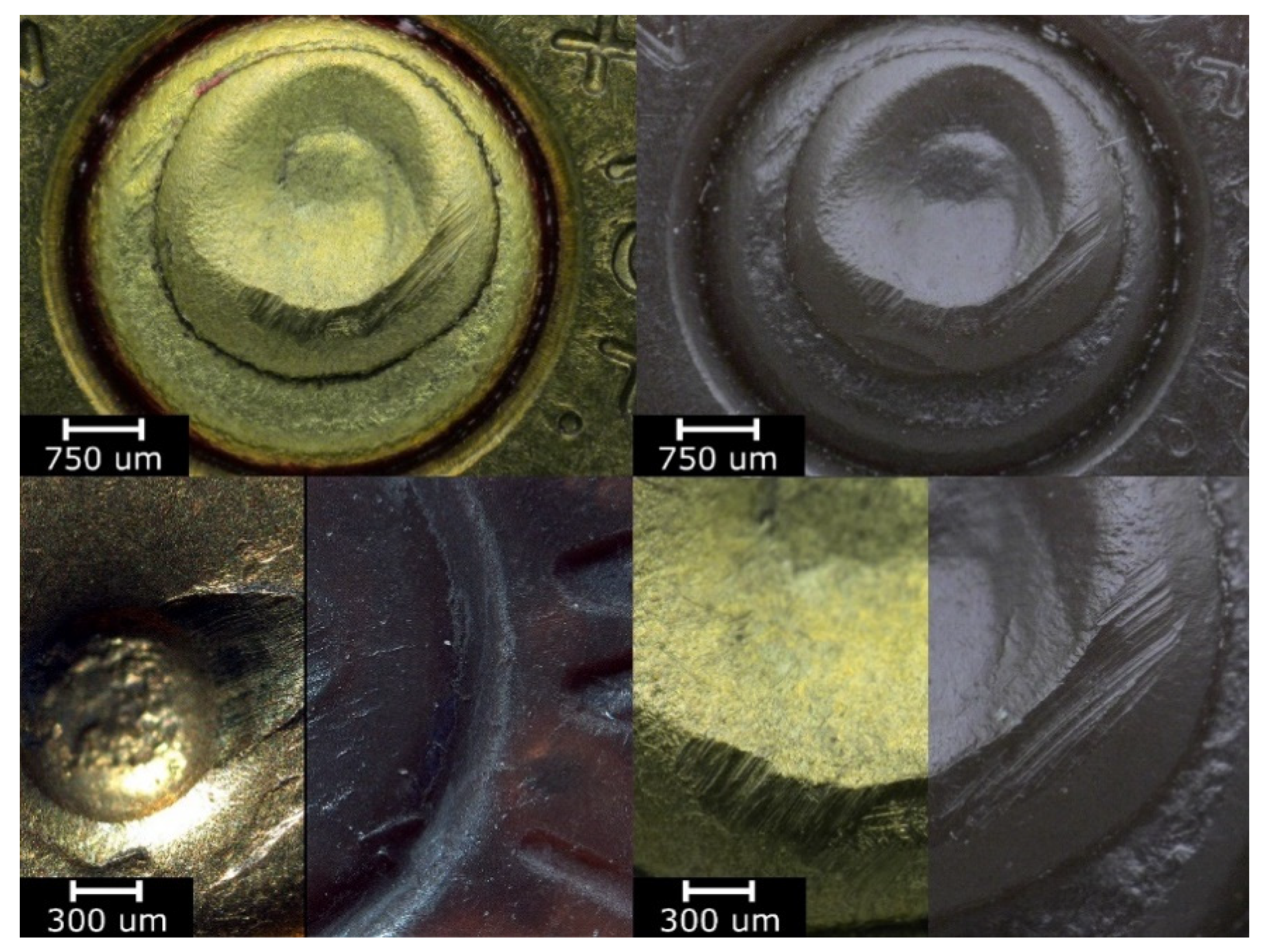
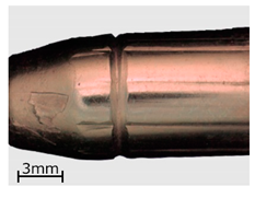
| Series | Bullets | Cartridge Case |
|---|---|---|
| 2 | 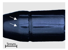 | 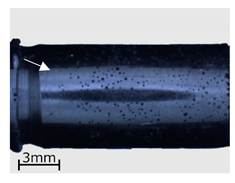 |
| 7 | 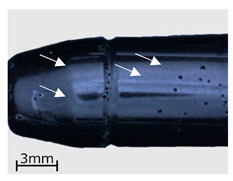 | 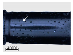 |
| 13 | 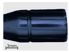 | 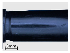 |
 |  |
Publisher’s Note: MDPI stays neutral with regard to jurisdictional claims in published maps and institutional affiliations. |
© 2021 by the authors. Licensee MDPI, Basel, Switzerland. This article is an open access article distributed under the terms and conditions of the Creative Commons Attribution (CC BY) license (http://creativecommons.org/licenses/by/4.0/).
Share and Cite
Frankiewicz, M.; Kobiela, K.; Kurzynowski, T. Possibility for Replicating Mechanoscopic Surface Marks in the Hybrid Vacuum-Pressure Casting Process. Polymers 2021, 13, 874. https://doi.org/10.3390/polym13060874
Frankiewicz M, Kobiela K, Kurzynowski T. Possibility for Replicating Mechanoscopic Surface Marks in the Hybrid Vacuum-Pressure Casting Process. Polymers. 2021; 13(6):874. https://doi.org/10.3390/polym13060874
Chicago/Turabian StyleFrankiewicz, Mariusz, Karol Kobiela, and Tomasz Kurzynowski. 2021. "Possibility for Replicating Mechanoscopic Surface Marks in the Hybrid Vacuum-Pressure Casting Process" Polymers 13, no. 6: 874. https://doi.org/10.3390/polym13060874
APA StyleFrankiewicz, M., Kobiela, K., & Kurzynowski, T. (2021). Possibility for Replicating Mechanoscopic Surface Marks in the Hybrid Vacuum-Pressure Casting Process. Polymers, 13(6), 874. https://doi.org/10.3390/polym13060874