
Effect of Zirconia Nanofibers Structure Evolution on the Hardness and Young’s Modulus of Their Mats

Abstract
:1. Introduction
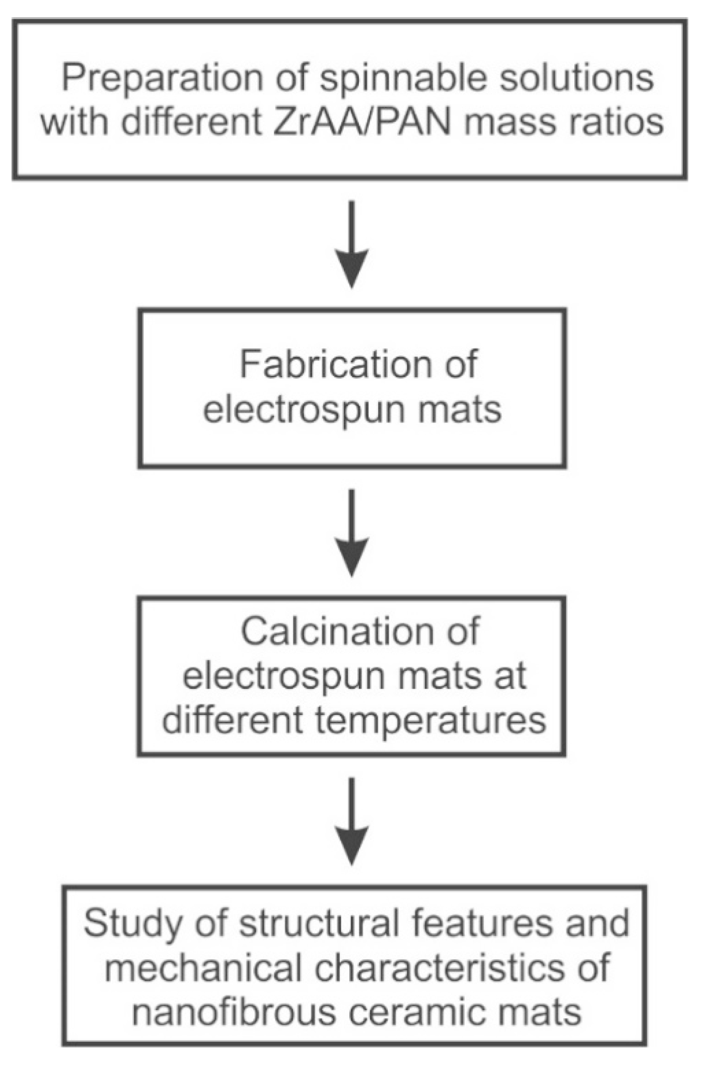
2. Materials and Methods
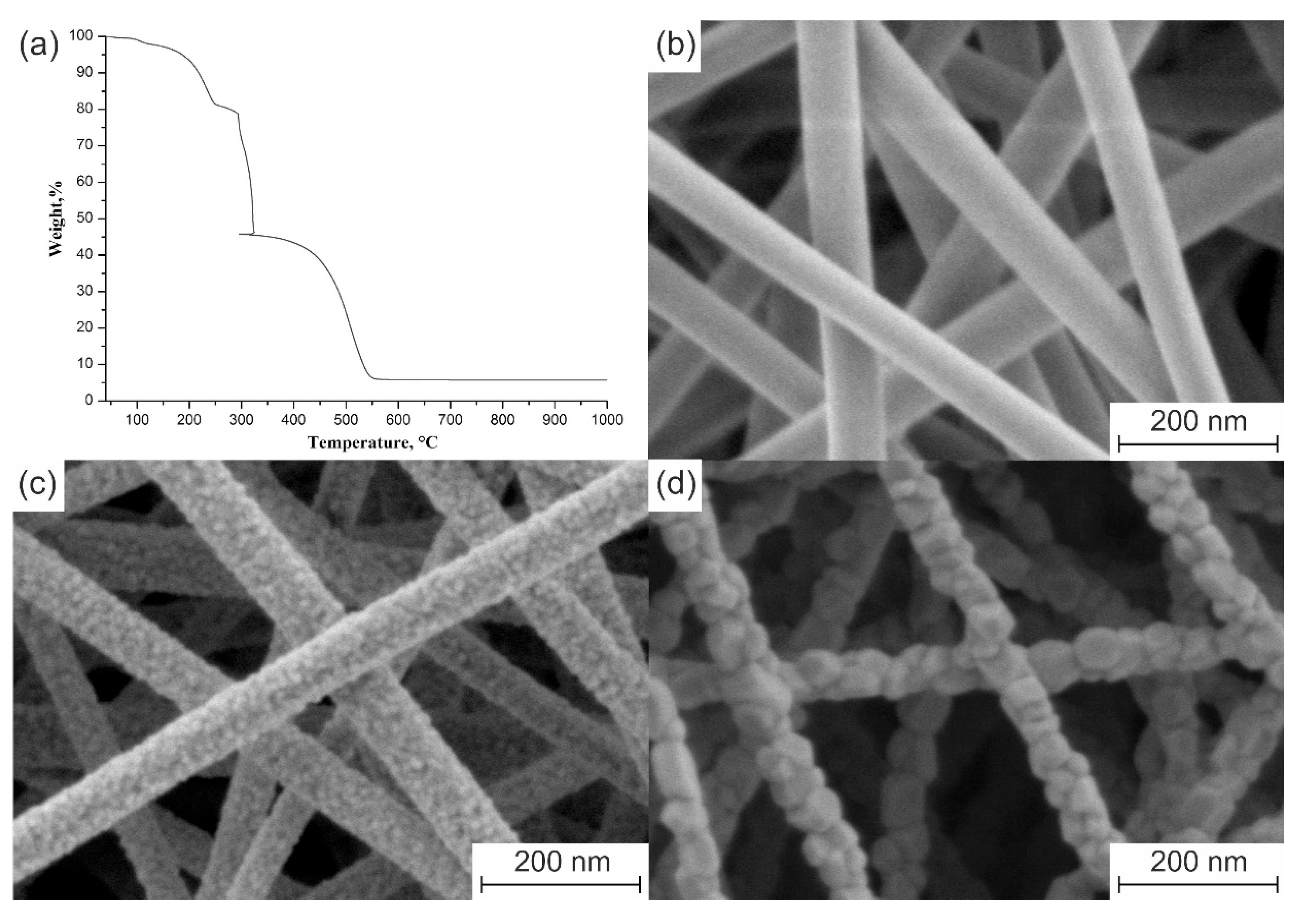
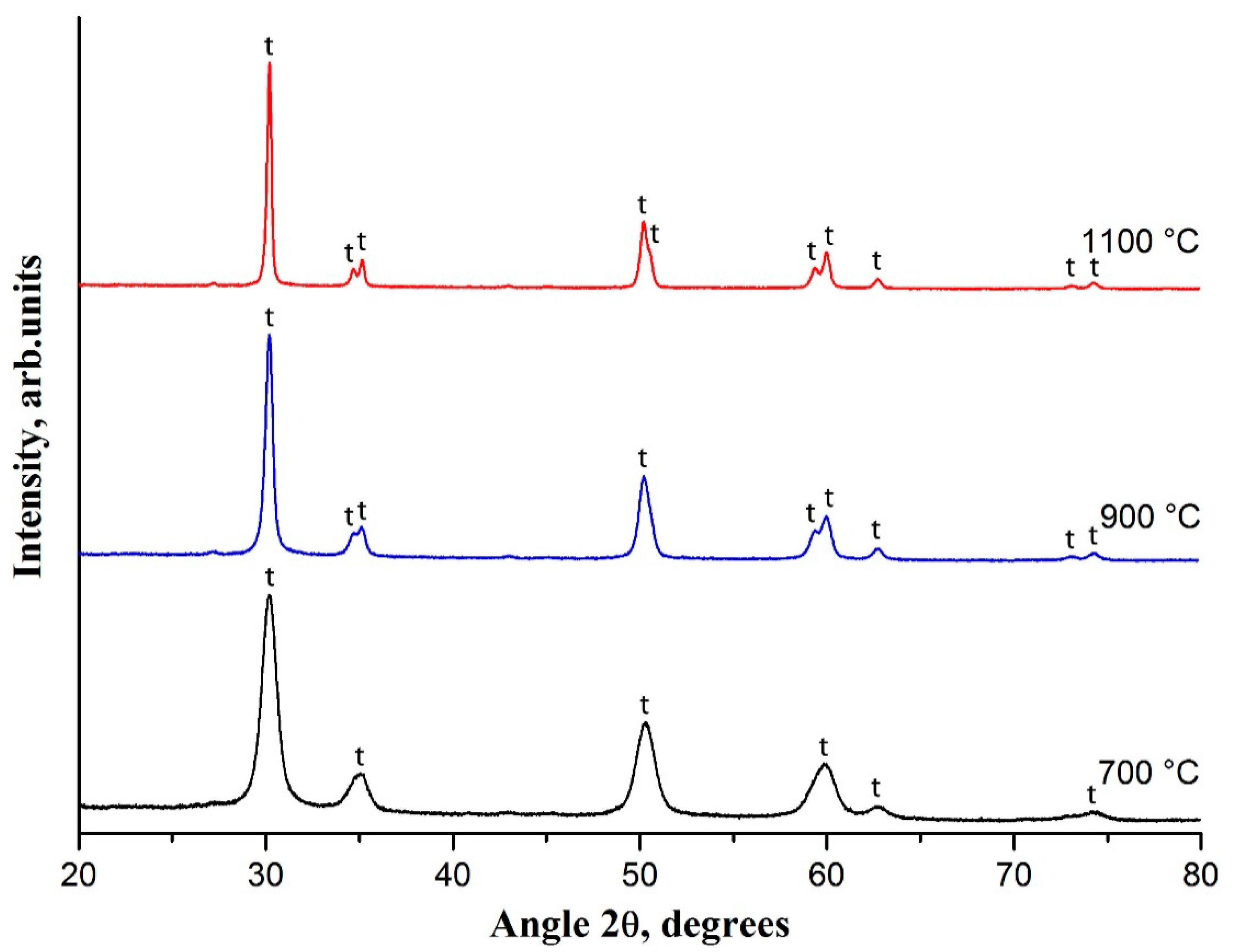
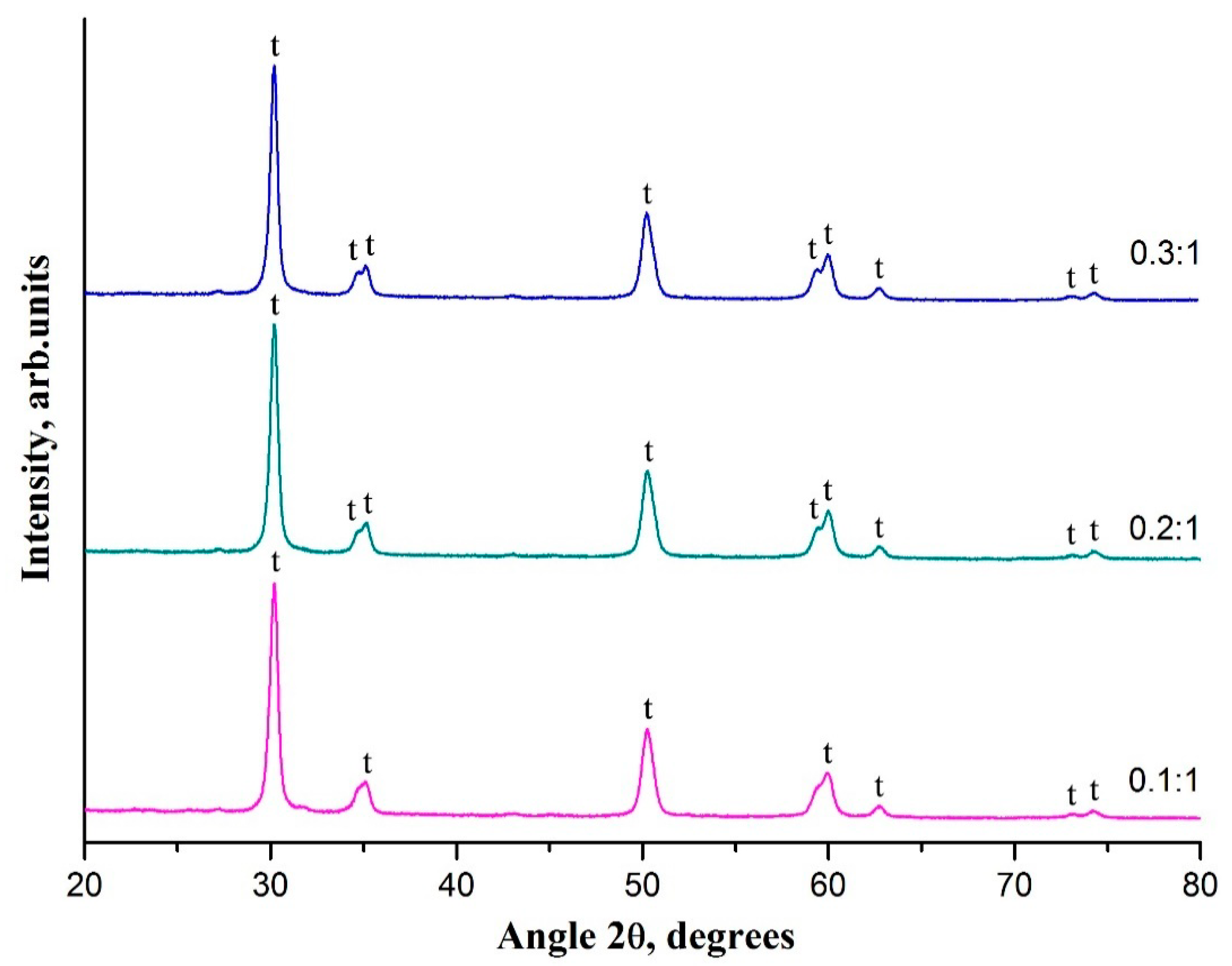
3. Results and Discussion
4. Conclusions
Author Contributions
Funding
Institutional Review Board Statement
Informed Consent Statement
Data Availability Statement
Conflicts of Interest
References
- Xue, J.; Wu, T.; Dai, Y.; Xia, Y. Electrospinning and electrospun nanofibers: Methods, materials, and applications. Chem. Rev. 2019, 119, 5298–5415. [Google Scholar] [CrossRef] [PubMed]
- Esfahani, H.; Jose, R.; Ramakrishna, S. Electrospun ceramic nanofiber mats today: Synthesis, properties, and applications. Materials 2017, 10, 1238. [Google Scholar] [CrossRef] [PubMed] [Green Version]
- Zhang, X.; Wu, X.; Shi, J. Additive manufacturing of zirconia ceramics: A state-of-the-art review. J. Mater. Res. Technol. 2020, 9, 9029–9048. [Google Scholar] [CrossRef]
- Gautam, C.; Joyner, J.; Gautam, A.; Rao, J.; Vajtai, R. Zirconia based dental ceramics: Structure, mechanical properties, biocompatibility and applications. Dalton Trans. 2016, 45, 19194–19215. [Google Scholar] [CrossRef]
- Koo, J.Y.; Lim, Y.; Kim, Y.B.; Byun, D.; Lee, W. Electrospun yttria-stabilized zirconia nanofibers for low-temperature solid oxide fuel cells. Int. J. Hydrog. Energy 2017, 42, 15903–15907. [Google Scholar] [CrossRef]
- Zhi, M.; Mariani, N.; Gemmen, R.; Gerdes, K.; Wu, N. Nanofiber scaffold for cathode of solid oxide fuel cell. Energy Environ. Sci. 2011, 4, 417–420. [Google Scholar] [CrossRef]
- Jing, P.; Liu, M.; Wang, P.; Yang, J.; Tang, M.; He, C.; Pu, Y.; Liu, M. Flexible nonwoven ZrO2 ceramic membrane as an electrochemically stable and flame-resistant separator for high-power rechargeable batteries. Chem. Eng. J. 2020, 388, 124259. [Google Scholar] [CrossRef]
- Mao, X.; Bai, Y.; Yu, J.; Ding, B. Flexible and highly temperature resistant polynanocrystalline zirconia nanofibrous membranes designed for air filtration. J. Am. Ceram. Soc. 2016, 99, 2760–2768. [Google Scholar] [CrossRef]
- Tang, Y.; Liu, Z.; Zhao, K.; Fu, S. Adsorption and separation properties of positively charged ZrO2 nanofibrous membranes fabricated by electrospinning. RSC Adv. 2017, 7, 42505–42512. [Google Scholar] [CrossRef] [Green Version]
- Ávila-Martínez, A.K.; Roque-Ruiz, J.H.; Torres-Pérez, J.; Medellín-Castillo, N.A.; Reyes-López, S.Y. Allura Red dye sorption onto electrospun zirconia nanofibers. Environ. Technol. Innov. 2020, 18, 100760. [Google Scholar] [CrossRef]
- Jin, X.; Yuan, K.; Wang, X.; Li, C. Electrospun mesoporous zirconia nanofibers as effective biomimetic haloperoxidase for pollution conversion and separation. Surf. Interfaces 2021, 26, 101358. [Google Scholar] [CrossRef]
- Lee, C.; Shul, Y.-G.; Einaga, H. Silver and manganese oxide catalysts supported on mesoporous ZrO2 nanofiber mats for catalytic removal of benzene and diesel soot. Catal. Today 2017, 281 Pt 3, 460–466. [Google Scholar] [CrossRef]
- Ruiz-Rosas, R.; Bedia, J.; Rosas, J.M.; Lallave, M.; Loscertales, I.G.; Rodríguez-Mirasol, J.; Cordero, T. Methanol decomposition on electrospun zirconia nanofibers. Catal. Today 2012, 187, 77–87. [Google Scholar] [CrossRef]
- Xia, J.; Guo, H.; Cheng, M.; Chen, C.; Wang, M.; Xiang, Y.; Li, T.; Traversa, E. Electrospun zirconia nanofibers for enhancing the electrochemical synthesis of ammonia by artificial nitrogen fixation. J. Mater. Chem. A 2021, 9, 2145–2151. [Google Scholar] [CrossRef]
- Li, W.; Ren, Y.; Guo, Y. ZrO2/ZnO nanocomposite materials for chemiresistive butanol sensors. Sens. Actuators B-Chem. 2020, 308, 127658. [Google Scholar] [CrossRef]
- Gazquez, G.C.; Chen, H.; Veldhuis, S.A.; Solmaz, A.; Mota, C.; Boukamp, B.A.; van Blitterswijk, C.A.; ten Elshof, J.E.; Moroni, L. Flexible yttrium-stabilized zirconia nanofibers offer bioactive cues for osteogenic differentiation of human mesenchymal stromal cells. ACS Nano 2016, 10, 5789–5799. [Google Scholar] [CrossRef] [PubMed]
- Du, Z.; Zhou, X.; Ye, P.; Zeng, X.; Gan, C.L. Shape-memory actuation in aligned zirconia nanofibers for artificial muscle applications at elevated temperatures. ACS Appl. Nano Mater. 2020, 3, 2156. [Google Scholar] [CrossRef]
- Guo, H.; Chen, Y.; Li, Y.; Zhou, W.; Xu, W.; Pang, L.; Fan, X.; Jiang, S. Electrospun fibrous materials and their applications for electromagnetic interference shielding: A review. Compos. Part A Appl. Sci. Manuf. 2021, 143, 106309. [Google Scholar] [CrossRef]
- Yildirim, F.; Orhan, Z.; Khalili, S.; Chenari, H.M.; Aydoğan, Ş. Self-powered ZrO2 nanofibers/n-Si photodetector with high on/off ratio for detecting very low optical signal. J. Phys. D Appl. Phys. 2021, 54, 475101. [Google Scholar] [CrossRef]
- Lee, N.-W.; Yoon, K.R.; Lee, J.-Y.; Park, Y.; Pyo, S.-J.; Kim, G.-Y.; Ha, D.-H.; Ryu, W.-H. Highly conductive off-stoichiometric zirconium oxide nanofibers with controllable crystalline structures and bandgaps and improved electrochemical activities. ACS Appl. Energy Mater. 2019, 2, 3513. [Google Scholar] [CrossRef]
- Castkova, K.; Maca, K.; Sekaninova, J.; Nemcovsky, J.; Cihlar, J. Electrospinning and thermal treatment of yttria doped zirconia fibres. Ceram. Int. 2017, 43, 7581–7587. [Google Scholar] [CrossRef]
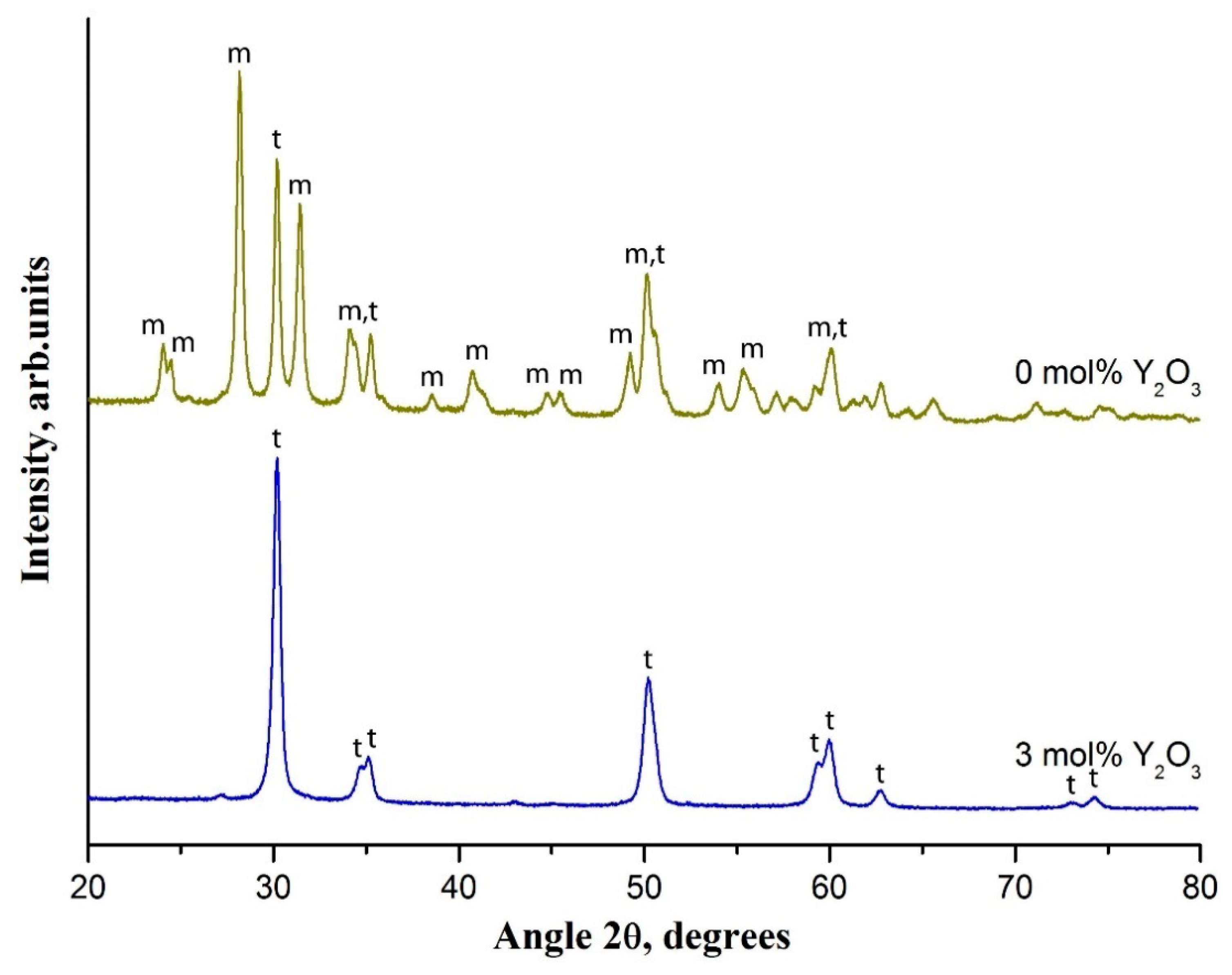
- Rodaev, V.V.; Razlivalova, S.S.; Tyurin, A.I.; Zhigachev, A.O.; Golovin, Y.I. Microstructure and phase composition of yttria-stabilized zirconia nanofibers prepared by high-temperature calcination of electrospun zirconium acetylacetonate/yttrium nitrate/polyacrylonitrile fibers. Fibers 2019, 7, 82. [Google Scholar] [CrossRef] [Green Version]
- Stanishevsky, A.; Yager, R.; Tomaszewska, J.; Binczarski, M.; Maniukiewicz, W.; Witońska, I.; Lukas, D. Structure and mechanical properties of nanofibrous ZrO2 derived from alternating field electrospun precursors. Ceram. Int. 2019, 45, 18672–18682. [Google Scholar] [CrossRef]
- Park, S.-J.; Chase, G.G.; Jeong, K.-U.; Kim, H.Y. Mechanical properties of titania nanofiber mats fabricated by electrospinning of sol–gel precursor. J. Sol-Gel Sci. Technol. 2010, 54, 188–194. [Google Scholar] [CrossRef]
- Lu, H.; Zhang, T.; Wang, X.P.; Fang, Q.F. Electrospun submicron bioactive glass fibers for bone tissue scaffold. J. Mater Sci. Mater. Med. 2009, 20, 793–798. [Google Scholar] [CrossRef]
- Paietta, R.C.; Campbell, S.E.; Ferguson, V.L. Influences of spherical tip radius, contact depth, and contact area on nanoindentation properties of bone. J. Biomech. 2011, 44, 285–290. [Google Scholar] [CrossRef] [PubMed]
- Fischer-Cripps, A.C. Nanoindentation, 3rd ed.; Springer: New York, NY, USA, 2011; p. 282. [Google Scholar]
- Arshad, S.N.; Naraghi, M.; Chasiotis, I. Strong carbon nanofibers from electrospun polyacrylonitrile. Carbon 2011, 49, 1710–1719. [Google Scholar] [CrossRef]
- Rodaev, V.V.; Zhigachev, A.O.; Korenkov, V.V.; Golovin, Y.I. The influence of zirconia precursor/binding polymer mass ratio in the intermediate electrospun composite fibers on the phase transformation of final zirconia nanofibers. Phys. Status Solidi A 2016, 213, 2352–2355. [Google Scholar] [CrossRef]
- Rodaev, V.V.; Razlivalova, S.S.; Zhigachev, A.O.; Vasyukov, V.M.; Golovin, Y.I. Preparation of zirconia nanofibers by electrospinning and calcination with zirconium acetylacetonate as precursor. Polymers 2019, 11, 1067. [Google Scholar] [CrossRef] [PubMed] [Green Version]
- Guo, G.-Y.; Chen, Y.-L. Unusual structural phase transition in nanocrystalline zirconia. Appl. Phys. A 2006, 84, 431–437. [Google Scholar] [CrossRef]
- Garvie, R.C. The occurrence of metastable tetragonal zirconia as a crystallite size effect. J. Phys. Chem. 1965, 69, 1238–1243. [Google Scholar] [CrossRef]
- Chevalier, J.; Gremillard, L.; Virkar, A.V.; Clarke, D.R. The tetragonal-monoclinic transformation in zirconia: Lessons learned and future trends. J. Am. Ceram. Soc. 2009, 92, 1901–1920. [Google Scholar] [CrossRef]
- Sun, G.-X.; Liu, F.-T.; Bi, J.-Q.; Wang, C.-A. Electrospun zirconia nanofibers and corresponding formation mechanism study. J. Alloys Compd. 2015, 649, 788–792. [Google Scholar] [CrossRef]
- Lange, F.F. Transformation-toughened ZrO2: Correlations between grain size control and composition in the system ZrO2-Y2O3. J. Am. Ceram. Soc. 1986, 69, 240–242. [Google Scholar] [CrossRef]
- Chen, Y.; Mao, X.; Shan, H.; Yang, J.; Wang, H.; Chen, S.; Tian, F.; Yu, J.; Ding, B. Free-standing zirconia nanofibrous membranes with robust flexibility for corrosive liquid filtration. RSC Adv. 2014, 4, 2756–2763. [Google Scholar] [CrossRef]
- Eckel, Z.C.; Zhou, C.; Martin, J.H.; Jacobsen, A.J.; Carter, W.B.; Schaedler, T.A. Additive manufacturing of polymer-derived ceramics. Science 2016, 351, 58–62. [Google Scholar] [CrossRef] [Green Version]
- Lee, S.-H.; Tekmen, C.; Sigmund, W.M. Three-point bending of electrospun TiO2 nanofibers. Mater. Sci. Eng. A 2005, 398, 77–81. [Google Scholar] [CrossRef]
- Sun, W. Fabrication and Characterization of Electrospun Alumina Nanofibre Reinforced Polycarbonate Composites. Ph.D. Thesis, Queen Mary University of London, London, UK, 2017; 201p. [Google Scholar]

| Calcination Temperature, °C | Specific Surface Area, m2/g | Pore Volume, cm3/g |
|---|---|---|
| 700 | 23.6 | 0.051 |
| 900 | 15.1 | 0.037 |
| 1100 | 9.3 | 0.022 |
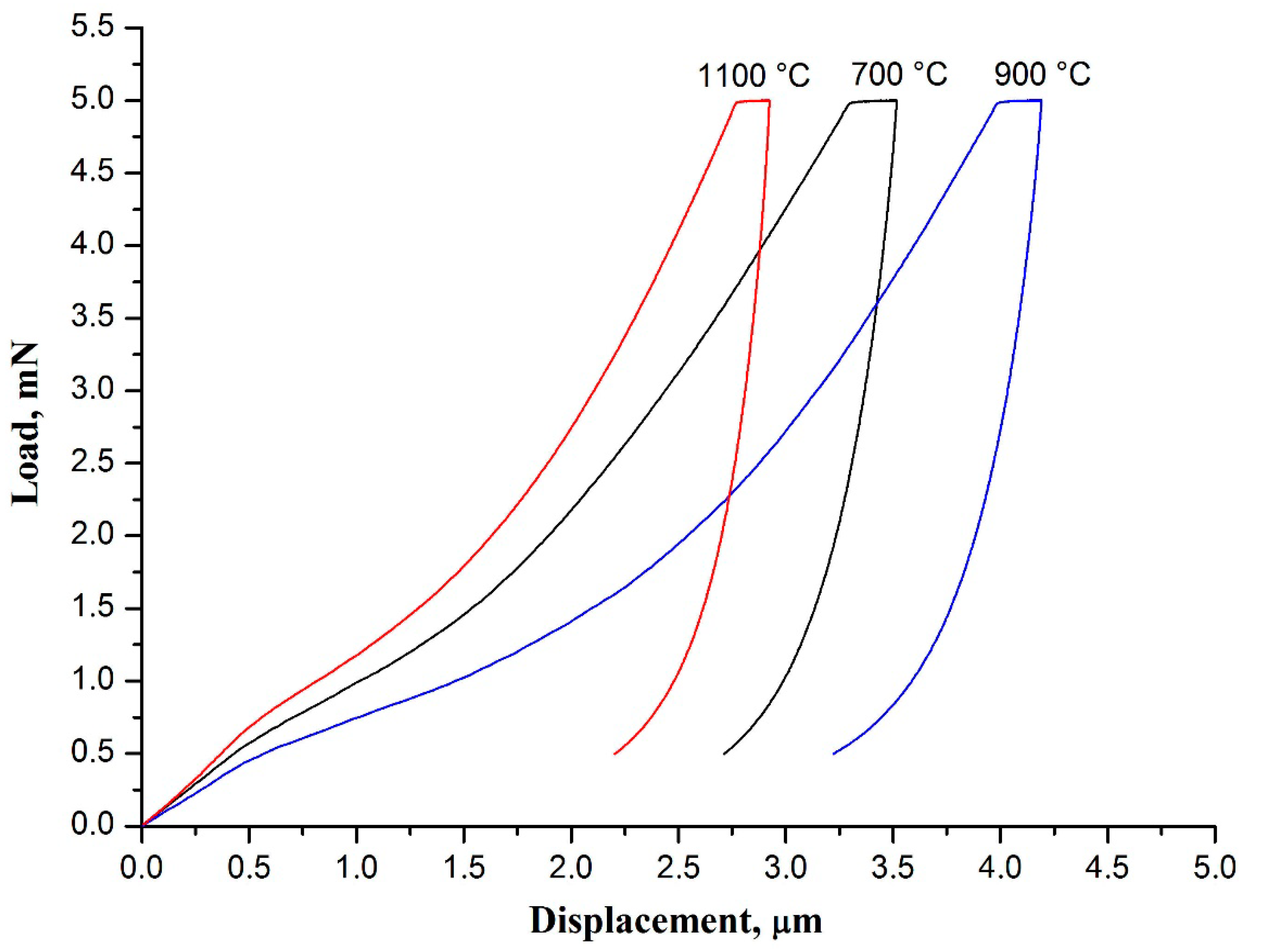
| Calcination Temperature, °C | Hardness, MPa | Young’s Modulus, MPa |
|---|---|---|
| 700 | 1.03 ± 0.05 | 171 ± 4 |
| 900 | 0.86 ± 0.05 | 133 ± 4 |
| 1100 | 1.25 ± 0.11 | 261 ± 12 |
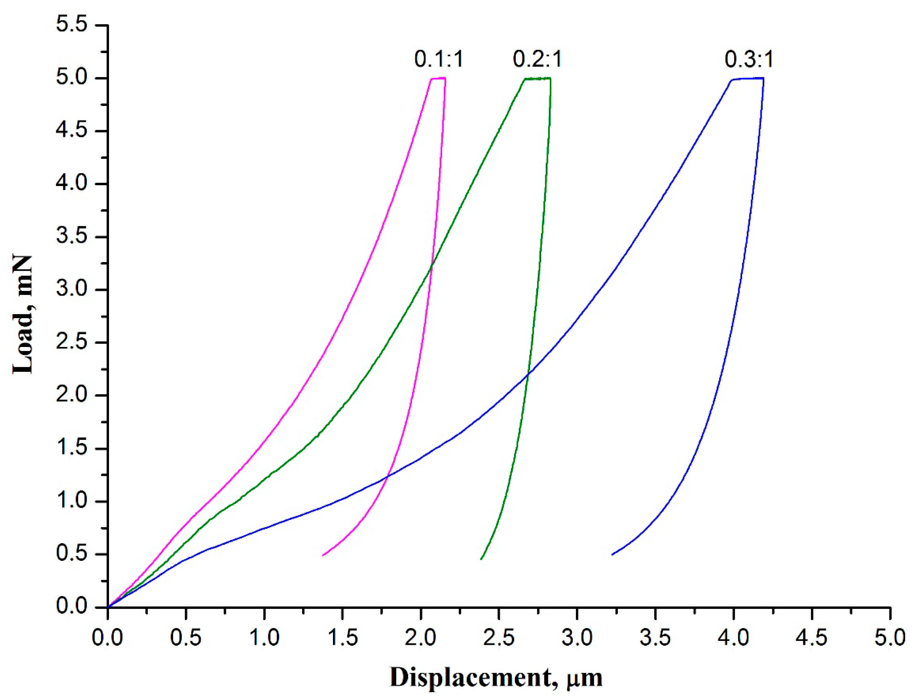
| ZrAA/PAN Mass Ratio | Hardness, MPa | Young’s Modulus, MPa |
|---|---|---|
| 0.1:1 | 1.67 ± 0.09 | 362 ± 13 |
| 0.2:1 | 1.11 ± 0.06 | 280 ± 8 |
| 0.3:1 | 0.86 ± 0.05 | 133 ± 4 |
Publisher’s Note: MDPI stays neutral with regard to jurisdictional claims in published maps and institutional affiliations. |
© 2021 by the authors. Licensee MDPI, Basel, Switzerland. This article is an open access article distributed under the terms and conditions of the Creative Commons Attribution (CC BY) license (https://creativecommons.org/licenses/by/4.0/).
Share and Cite
Rodaev, V.V.; Tyurin, A.I.; Razlivalova, S.S.; Korenkov, V.V.; Golovin, Y.I. Effect of Zirconia Nanofibers Structure Evolution on the Hardness and Young’s Modulus of Their Mats. Polymers 2021, 13, 3932. https://doi.org/10.3390/polym13223932
Rodaev VV, Tyurin AI, Razlivalova SS, Korenkov VV, Golovin YI. Effect of Zirconia Nanofibers Structure Evolution on the Hardness and Young’s Modulus of Their Mats. Polymers. 2021; 13(22):3932. https://doi.org/10.3390/polym13223932
Chicago/Turabian StyleRodaev, Vyacheslav V., Alexander I. Tyurin, Svetlana S. Razlivalova, Viktor V. Korenkov, and Yuri I. Golovin. 2021. "Effect of Zirconia Nanofibers Structure Evolution on the Hardness and Young’s Modulus of Their Mats" Polymers 13, no. 22: 3932. https://doi.org/10.3390/polym13223932
APA StyleRodaev, V. V., Tyurin, A. I., Razlivalova, S. S., Korenkov, V. V., & Golovin, Y. I. (2021). Effect of Zirconia Nanofibers Structure Evolution on the Hardness and Young’s Modulus of Their Mats. Polymers, 13(22), 3932. https://doi.org/10.3390/polym13223932