
Innovation in Aircraft Cabin Interior Panels. Part II: Technical Assessment on Replacing Glass Fiber with Thermoplastic Polymers and Panels Fabricated Using Vacuum Forming Process

 ,
,  , ,
, ,
Abstract
:1. Introduction
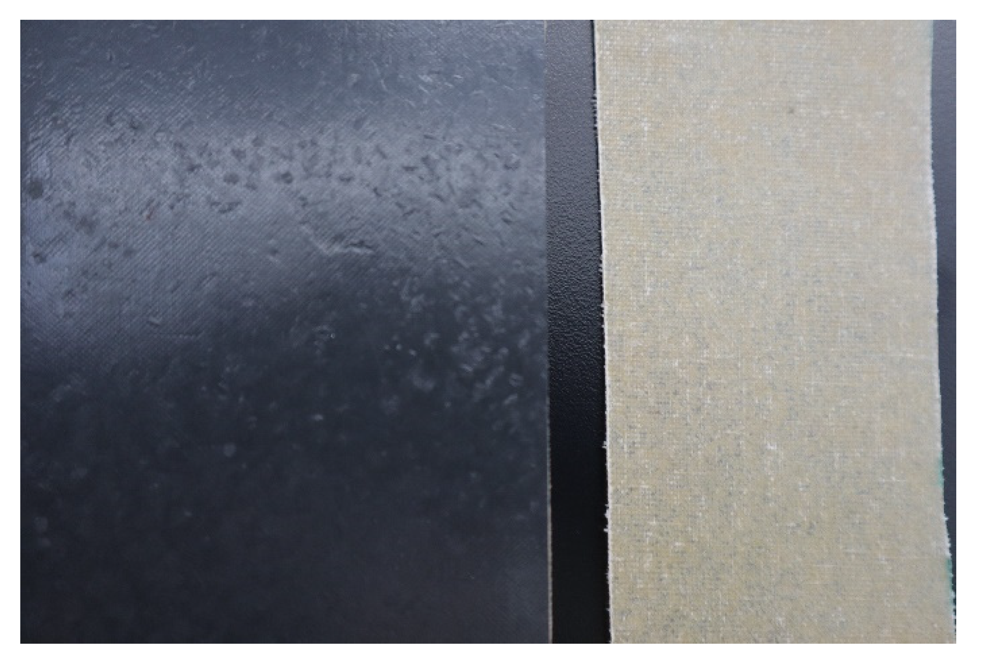
2. Materials
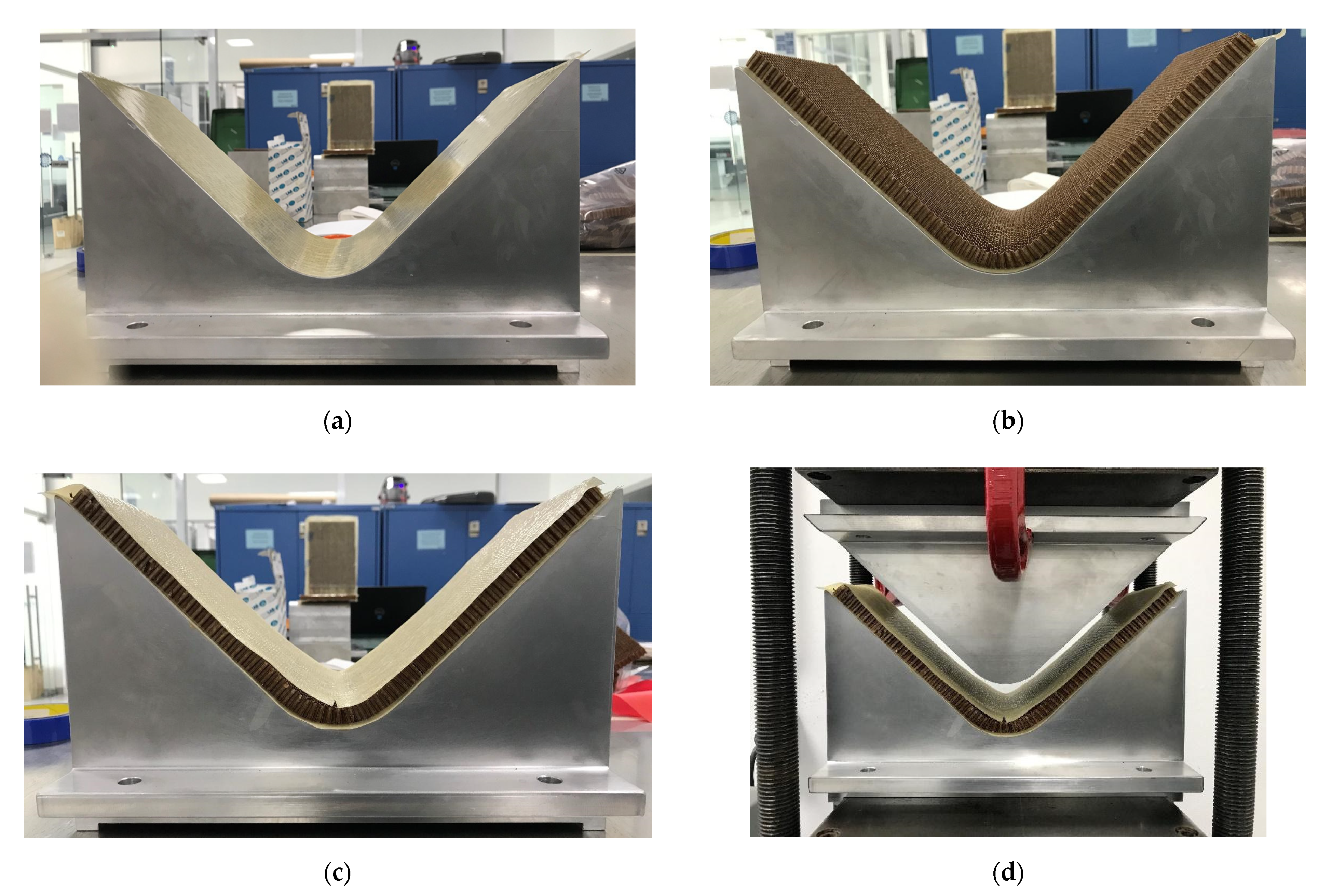
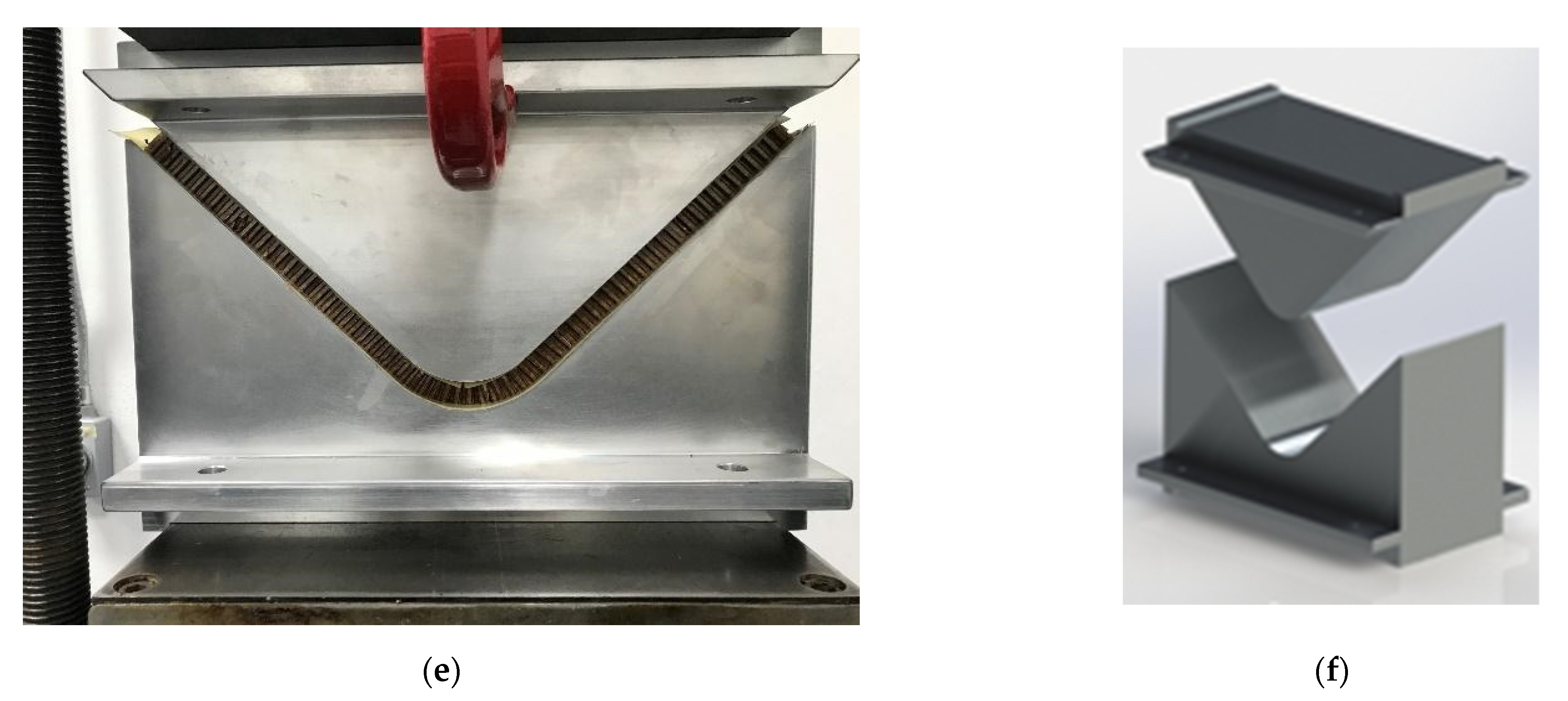
3. Manufacturing Panels
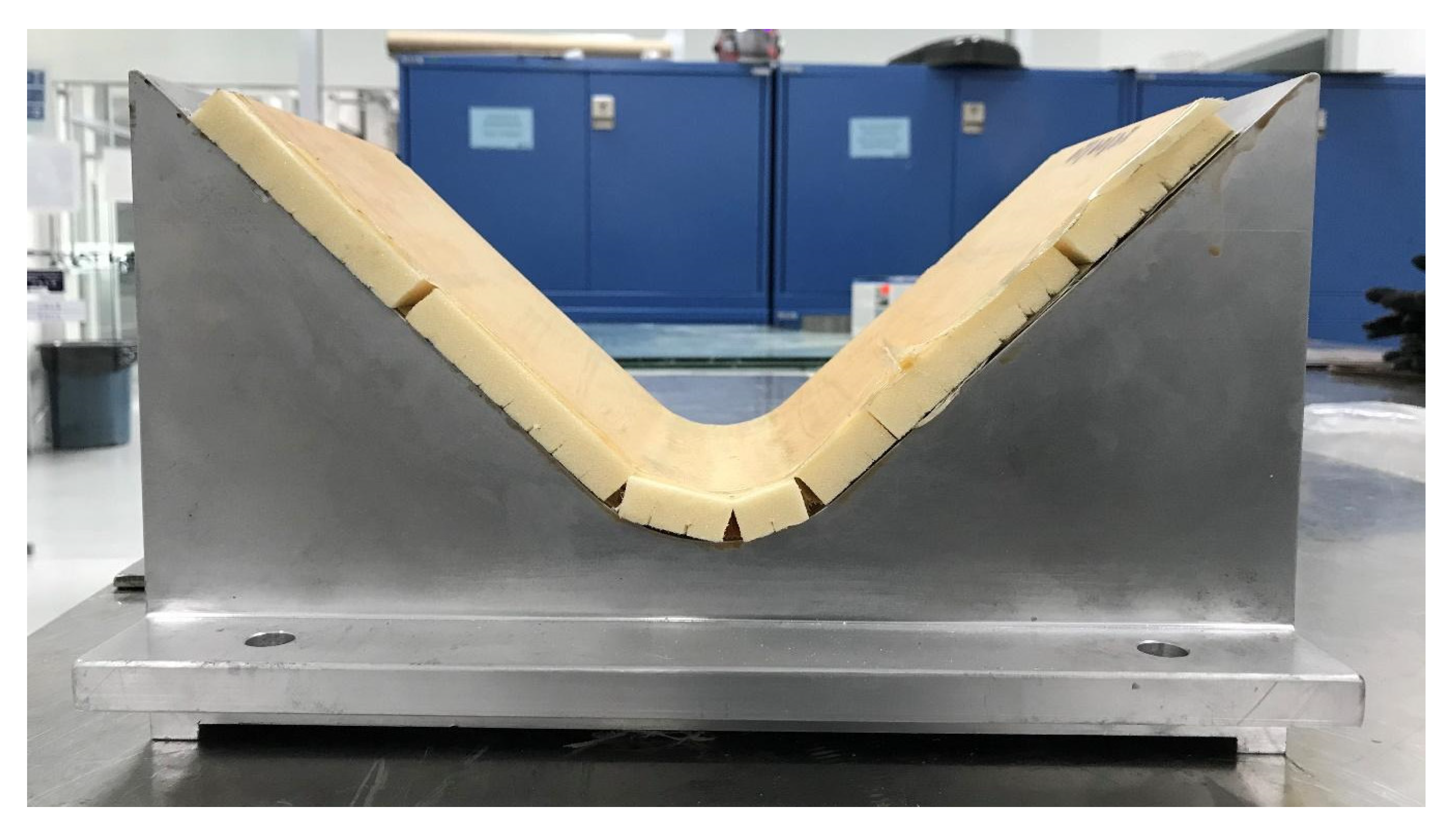
- Three layers of mold release agent were applied to the two components of the V-shaped mold. With that covered, two layers of prepreg fiberglass were carefully stacked on both faces of the V-shaped mold, as presented in Figure 3.
- Two layers of GF prepreg were placed on one of the faces of the V-shaped mold.
- The HC specimen was placed on the GF prepreg layers, and two additional layers were placed on the top of the HC to build the sandwich composite configuration.
- The mold is closed slowly to transfer the temperature from the hot plates to the V-shaped mold. The preheated process consisted of 256 °F during 30 min.
- After the preheated process, the mold is closed, supplying a constant pressure of 20 psi and a temperature of 256 °F for one hour. Digital temperature recorder and thermocouples on both sides of the V-shape mold were used to monitor and verify the adequate pressure and temperature during the curing process.
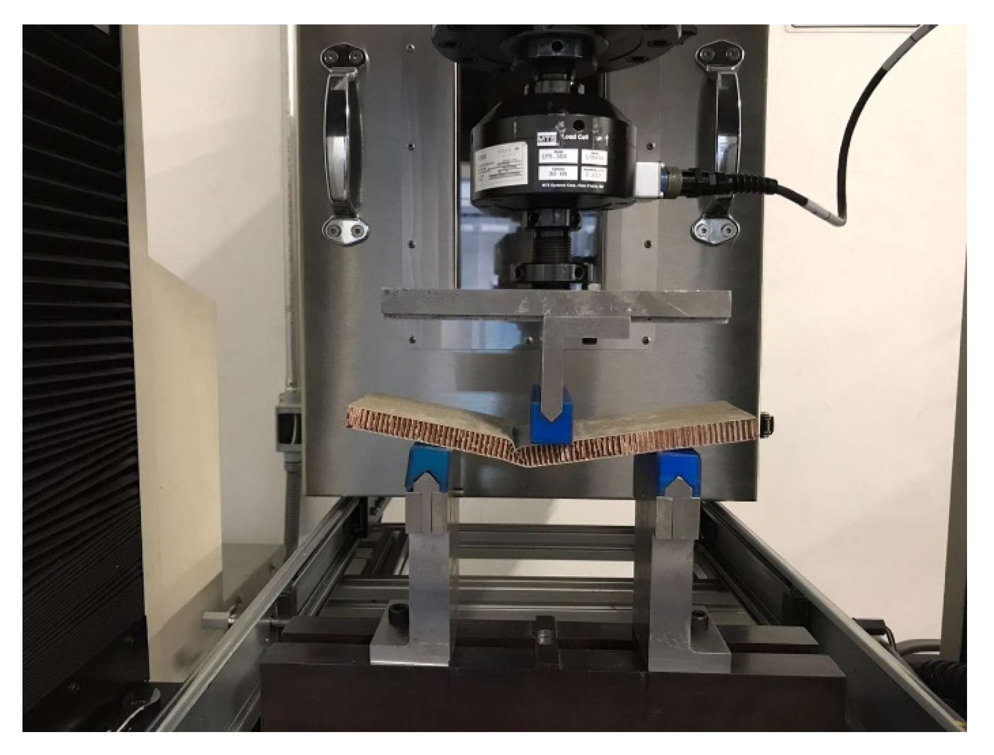
4. Results
5. Conclusions
Author Contributions
Funding
Institutional Review Board Statement
Informed Consent Statement
Data Availability Statement
Acknowledgments
Conflicts of Interest
References
- Egan, B.; McCarthy, C.T.; McCarthy, M.A.; Gray, P.J.; O’Higgins, R.M. Static and high-rate loading of single and multi-bolt carbon-epoxy aircraft fuselage joints. Compos. Part A Appl. Sci. Manuf. 2013, 53, 97–108. [Google Scholar] [CrossRef] [Green Version]
- Soutis, C. Carbon fiber reinforced plastics in aircraft construction. Mater. Sci. Eng. A 2005, 412, 171–176. [Google Scholar] [CrossRef]
- Mccarthy, C.; Mccarthy, M. Experimental and Computational Studies of Mechanically Fastened Joints in Composite Aircraft Structures Dept. of Mechanical and Aeronautical Engineering University of Limerick. In Proceedings of the 1st CEAS European Air and Space Conference, Berlin, Germany, 10–13 September 2007. [Google Scholar] [CrossRef]
- Impact, R.; Store, K.; Reserved, A.R. Aircraft Cabin Interiors Market—Global Forecast to 2025; ASDR-559916; MarketsandMarkets: Hadapsar, India, 2020. [Google Scholar]
- Hiemstra-van Mastrigt, S.; Smulders, M.; Bouwens, J.M.A.; Vink, P. Chapter 61—Designing aircraft seats to fit the human body contour. In DHM and Posturography; Scataglini, S., Paul, G., Eds.; Academic Press: Cambridge, MA, USA, 2019; pp. 781–789. ISBN 9780128167137. [Google Scholar]
- Piedra, S.; Martinez, E.; Escalante-Velazquez, C.A.; Jimenez, S.M.A. Computational aerodynamics analysis of a light sport aircraft: Compliance study for stall speed and longitudinal stability certification requirements. Aerosp. Sci. Technol. 2018, 82–83, 234–242. [Google Scholar] [CrossRef]
- Torres, M.; Piedra, S.; Ledesma, S.; Escalante-Velázquez, C.A.; Angelucci, G. Manufacturing process of high performance-low cost composite structures for light sport aircrafts. Aerospace 2019, 6, 11. [Google Scholar] [CrossRef] [Green Version]
- Lyon, R.E. 20—Materials with reduced flammability in aerospace and aviation. In Advances in Fire Retardant Materials; Woodhead Publishing Series in Textiles; Horrocks, A.R., Price, D.B., Eds.; Woodhead Publishing: Sawston, UK, 2008; pp. 573–598. ISBN 9781845692629. [Google Scholar]
- Di Franco, G.; Fratini, L.; Pasta, A. Influence of the distance between rivets in self-piercing riveting bonded joints made of carbon fiber panels and AA2024 blanks. Mater. Des. 2012, 35, 342–349. [Google Scholar] [CrossRef]
- Torres, M.; Franco-Urquiza, E.A.; Hernández-Moreno, H.; González-Villa, M.A. Mechanical Behavior of a Fuselage Stiffened Carbon-Epoxy Panel under Debonding Load. J. Aeronaut. Aerosp. Eng. 2018, 7, 2–6. [Google Scholar] [CrossRef]
- Found, M.S.; Friend, M.J. Evaluation of CFRP panels with scarf repair patches. Compos. Struct. 1995, 32, 115–122. [Google Scholar] [CrossRef]
- Kradinov, V.; Hanauska, J.; Barut, A.; Madenci, E.; Ambur, D.R. Bolted patch repair of composite panels with a cutout. Compos. Struct. 2002, 56, 423–444. [Google Scholar] [CrossRef]
- Whitty, J.P.M.; Alderson, A.; Myler, P.; Kandola, B. Towards the design of sandwich panel composites with enhanced mechanical and thermal properties by variation of the in-plane Poisson’s ratios. Compos. Part A Appl. Sci. Manuf. 2003, 34, 525–534. [Google Scholar] [CrossRef]
- Seibert, H.F. Applications for PMI foams in aerospace sandwich structures. Reinf. Plast. 2006, 50, 44–48. [Google Scholar] [CrossRef]
- Castanie, B.; Bouvet, C.; Ginot, M. Review of composite sandwich structure in aeronautic applications. Compos. Part C Open Access 2020, 1, 100004. [Google Scholar] [CrossRef]
- Birman, V.; Kardomateas, G.A. Review of current trends in research and applications of sandwich structures. Compos. Part B Eng. 2018, 142, 221–240. [Google Scholar] [CrossRef]
- Alila, F.; Casari, P. Fatigue damage and failure analysis of honeycomb sandwich. Procedia Struct. Integr. 2019, 19, 101–105. [Google Scholar] [CrossRef]
- Mills, N. (Ed.) Sandwich panel case study. In Polymer Foams Handbook; Elsevier: Oxford, UK, 2007; pp. 425–447. ISBN 9780750680691. [Google Scholar]
- Franco-Urquiza, E.A.; Dollinger, A.; Torres-Arellano, M.; Piedra, S.; Alcántara Llanas, P.I.; Rentería-Rodríguez, V.; Zarate Pérez, C. Innovation in Aircraft Cabin Interior Panels Part I: Technical Assessment on Replacing the Honeycomb with Structural Foams and Evaluation of Optimal Curing of Prepreg Fiberglass. Polymers 2021, 13, 3207. [Google Scholar] [CrossRef]
- Han, B.; Wang, W.; Zhang, Z.; Zhang, Q.; Jin, F.; Lu, T. Performance enhancement of sandwich panels with honeycomb–corrugation hybrid core. Theor. Appl. Mech. Lett. 2016, 6, 54–59. [Google Scholar] [CrossRef] [Green Version]
- Shahdin, A.; Mezeix, L.; Bouvet, C.; Morlier, J.; Gourinat, Y. Fabrication and mechanical testing of glass fiber entangled sandwich beams: A comparison with honeycomb and foam sandwich beams. Compos. Struct. 2009, 90, 404–412. [Google Scholar] [CrossRef] [Green Version]
- ASTM C393/C393M-20 Standard Test Method for Core Shear Properties of Sandwich Constructions by Beam Flexure; ASTM International: West Conshohocken, PA, USA, 2020. [CrossRef]
- Ogorkiewicz, R.M. Analysis and Design of Structural Sandwich Panels; Howard, G., Ed.; Allen Pergamon Press: Oxford, UK, 1969; 283p. [Google Scholar]
- Zenkert, D. Handbook of Sandwich Construction; Engineering Materials Advisory Services Ltd.: Worcester, UK, 1997. [Google Scholar]
- Laustsen, S.; Lund, E.; Kühlmeier, L.; Thomsen, O.T. Failure behaviour of grid-scored foam cored composite sandwich panels for wind turbine blades subjected to realistic multiaxial loading conditions. J. Sandw. Struct. Mater. 2014, 16, 481–510. [Google Scholar] [CrossRef] [Green Version]
- Sun, Z.; Shi, S.; Guo, X.; Hu, X.; Chen, H. On compressive properties of composite sandwich structures with grid reinforced honeycomb core. Compos. Part B Eng. 2016, 94, 245–252. [Google Scholar] [CrossRef]
- Barbero, E.J. Finite Element Analysis of Composite Materials Using Ansys®; CRC Press: Boca Raton, FL, USA, 2013; Volume 3, ISBN 9780429185250. [Google Scholar]


| Panel Configuration | Faces | Core | Representation |
|---|---|---|---|
| GF/HC/GF | Glass fiber prepreg | Honeycomb | Reference panels |
| GF/Foam/GF | Glass fiber prepreg | Foam | Experimental panels |
| ABS/Foam/ABS | Thermoplastic ABS | Foam | Disruptive panels |
| Composite Panel | Max Normal Strength (MPa) | Max Shear Strength (kPa) | Max Deflection (mm) |
|---|---|---|---|
| GF/HC/GF | 17.44 ± 0.62 | 57.5 ± 0.62 | 13.80 ± 0.62 |
| GF/Foam/GF | 2.22 ± 0.62 | 56.1 ± 0.62 | 41.39 ± 0.62 |
| GF/gridding foam/GF | 0.90 ± 0.62 | 62.3 ± 0.62 | 37.87 ± 0.62 |
| ABS/HC/ABS | 6.52 ± 0.02 | 240.3 ± 0.12 | 32.71 ± 2.50 |
| ABS/Foam/ABS | 10.48 ± 0.03 | 390.4 ± 0.10 | 34.29 ± 0.43 |
| ABS/gridding foam/ABS | 5.14 ± 0.87 | 170.2 ± 0.09 | 51.65 ± 2.63 |
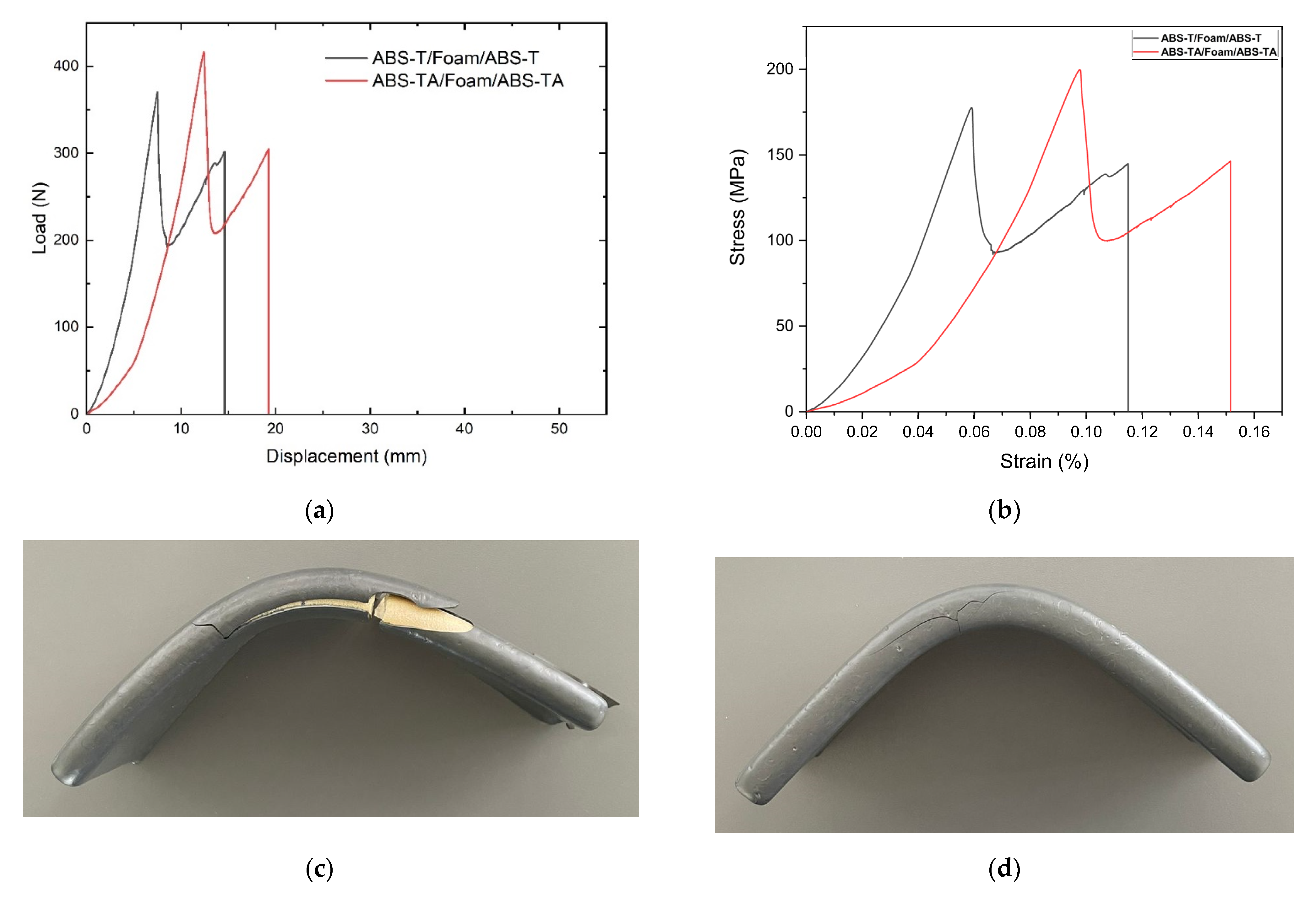
| ABS-T/Foam/ABS-T | 9.29 ± 1.47 | 320.2 ± 5.96 | 15.87 ± 3.71 |
| ABS-TA/Foam/ABS-TA | 7.13 ± 2.68 | 253.6 ± 8.53 | 15.37 ± 2.31 |
Publisher’s Note: MDPI stays neutral with regard to jurisdictional claims in published maps and institutional affiliations. |
© 2021 by the authors. Licensee MDPI, Basel, Switzerland. This article is an open access article distributed under the terms and conditions of the Creative Commons Attribution (CC BY) license (https://creativecommons.org/licenses/by/4.0/).
Share and Cite
Franco-Urquiza, E.A.; Alcántara Llanas, P.I.; Rentería-Rodríguez, V.; Saleme, R.S.; Ramírez Aguilar, R.; Zarate Pérez, C.; Torres-Arellano, M.; Piedra, S. Innovation in Aircraft Cabin Interior Panels. Part II: Technical Assessment on Replacing Glass Fiber with Thermoplastic Polymers and Panels Fabricated Using Vacuum Forming Process. Polymers 2021, 13, 3258. https://doi.org/10.3390/polym13193258
Franco-Urquiza EA, Alcántara Llanas PI, Rentería-Rodríguez V, Saleme RS, Ramírez Aguilar R, Zarate Pérez C, Torres-Arellano M, Piedra S. Innovation in Aircraft Cabin Interior Panels. Part II: Technical Assessment on Replacing Glass Fiber with Thermoplastic Polymers and Panels Fabricated Using Vacuum Forming Process. Polymers. 2021; 13(19):3258. https://doi.org/10.3390/polym13193258
Chicago/Turabian StyleFranco-Urquiza, Edgar Adrián, Perla Itzel Alcántara Llanas, Victoria Rentería-Rodríguez, Raúl Samir Saleme, Rodrigo Ramírez Aguilar, Cecilia Zarate Pérez, Mauricio Torres-Arellano, and Saúl Piedra. 2021. "Innovation in Aircraft Cabin Interior Panels. Part II: Technical Assessment on Replacing Glass Fiber with Thermoplastic Polymers and Panels Fabricated Using Vacuum Forming Process" Polymers 13, no. 19: 3258. https://doi.org/10.3390/polym13193258
APA StyleFranco-Urquiza, E. A., Alcántara Llanas, P. I., Rentería-Rodríguez, V., Saleme, R. S., Ramírez Aguilar, R., Zarate Pérez, C., Torres-Arellano, M., & Piedra, S. (2021). Innovation in Aircraft Cabin Interior Panels. Part II: Technical Assessment on Replacing Glass Fiber with Thermoplastic Polymers and Panels Fabricated Using Vacuum Forming Process. Polymers, 13(19), 3258. https://doi.org/10.3390/polym13193258