
Aging Mechanisms and Non-Destructive Aging Indicators of XLPE/CSPE Unshielded LV Nuclear Power Cables Subjected to Simultaneous Radiation-Mechanical Aging


Abstract
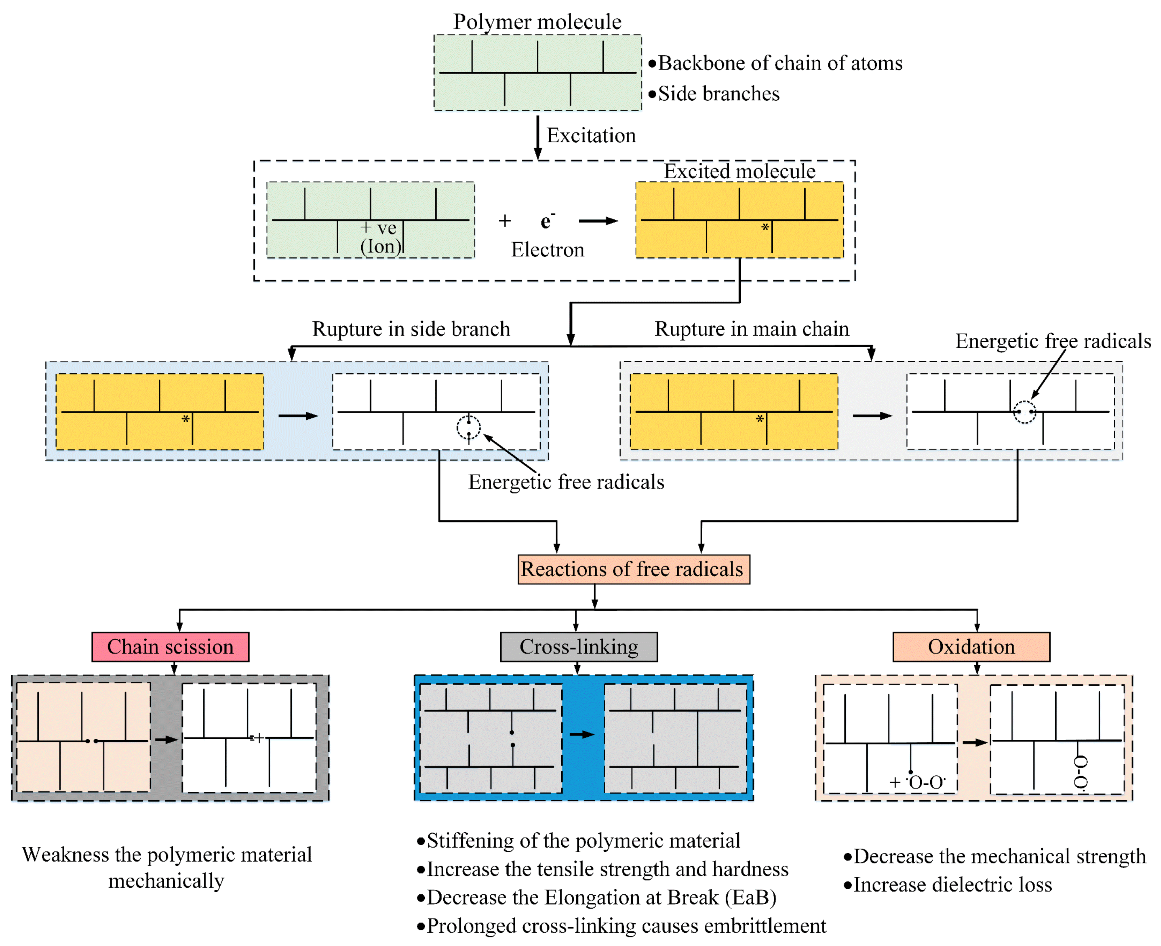
:1. Introduction
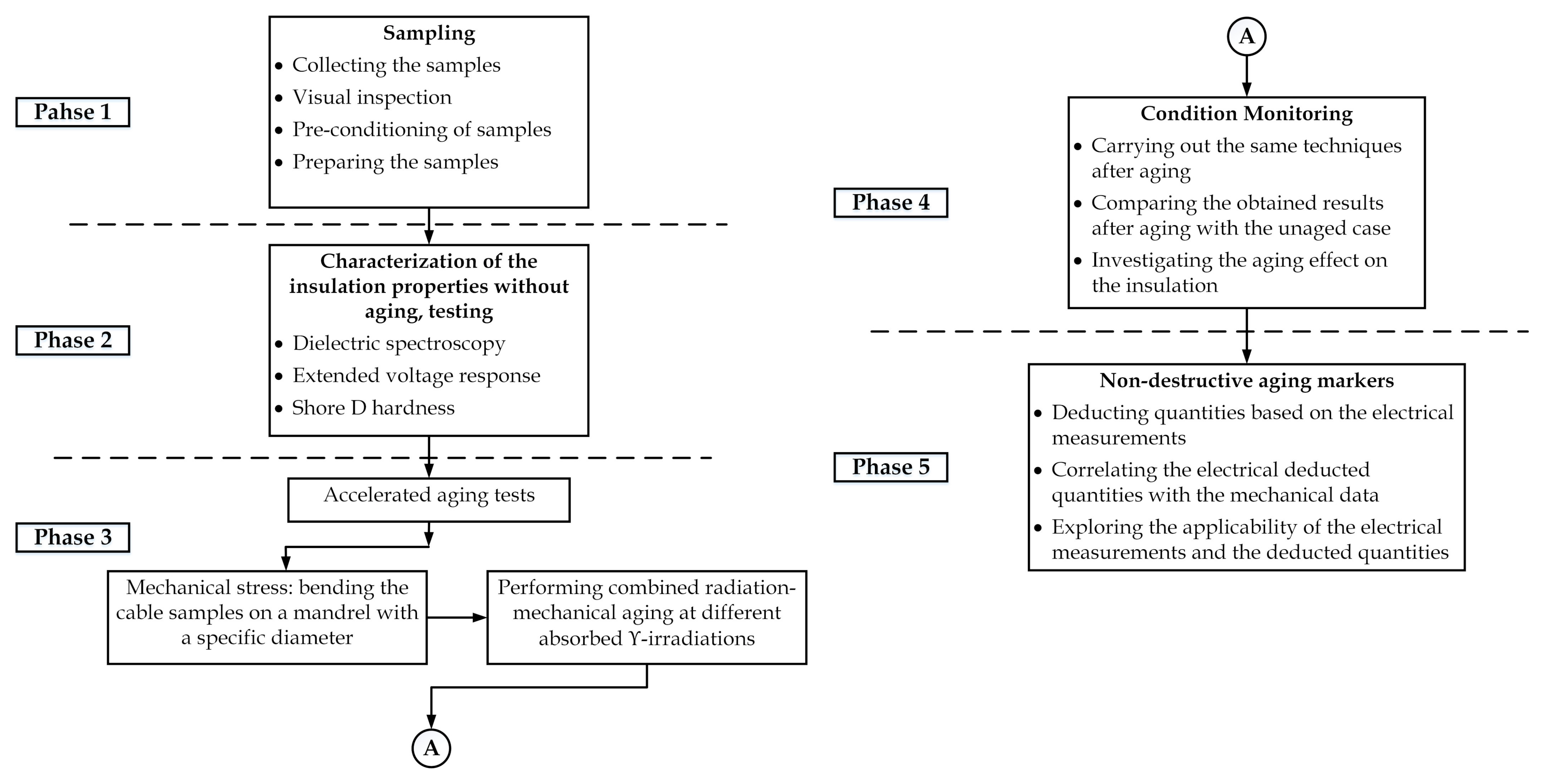
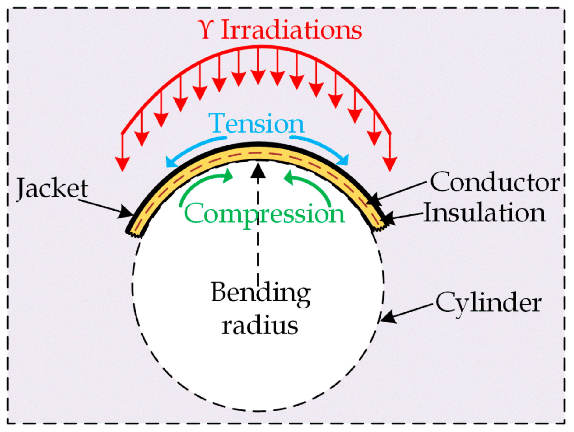
2. Research Approach
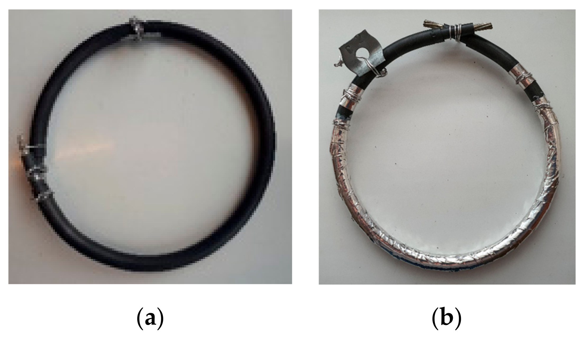
3. Materials and Samples Preparation
4. Aging Exposure
5. Methods
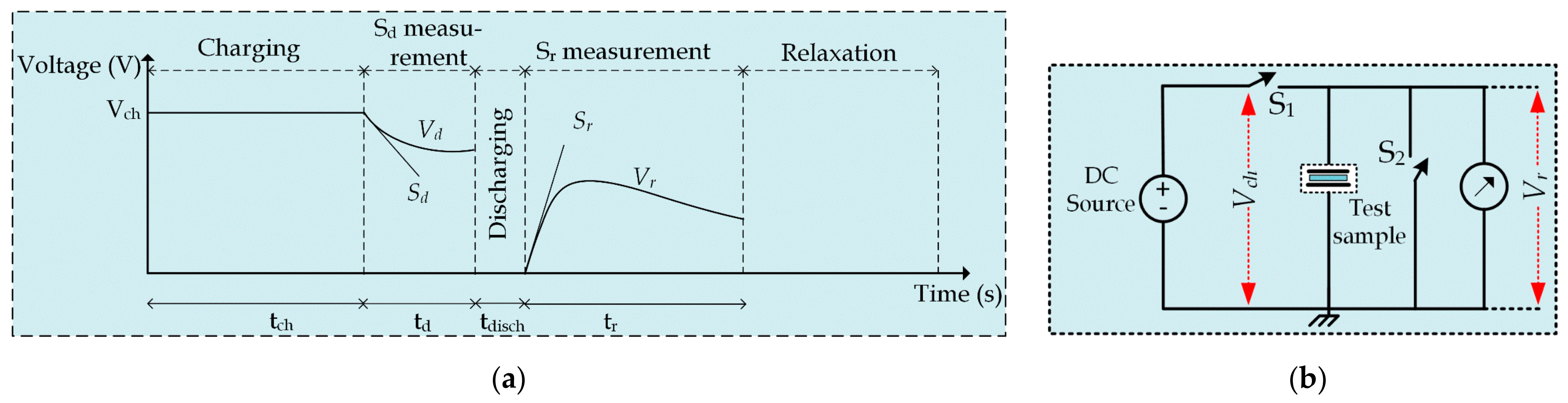
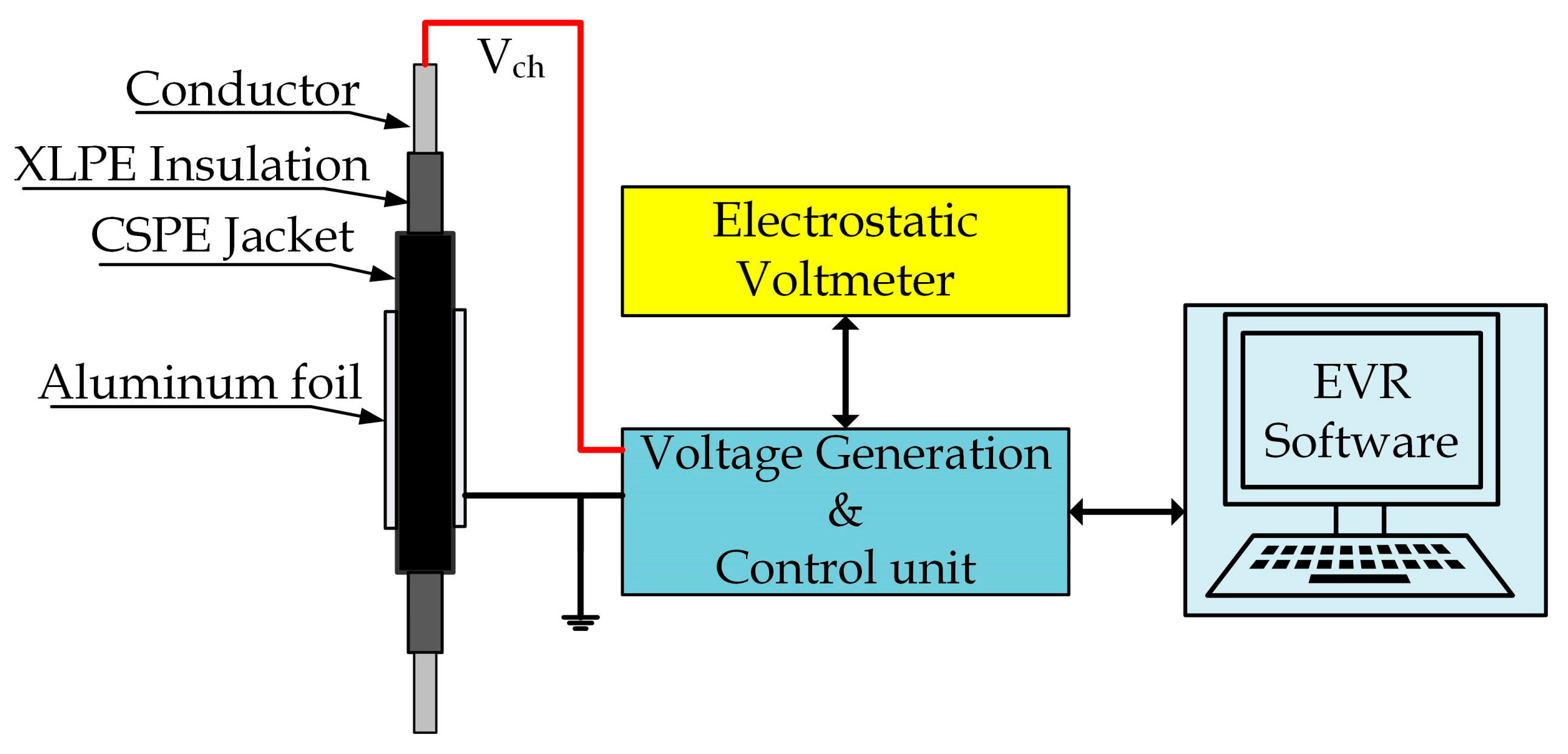
5.1. Extended Voltage Response (EVR)
- Charging voltage (Vch): 1 kV;
- Charging time (tch): 4000 sec;
- Discharging time (tdisch): from 1 sec (tdisch1) to 2000 sec (tdisch20);
- Number of discharging periods: 20.
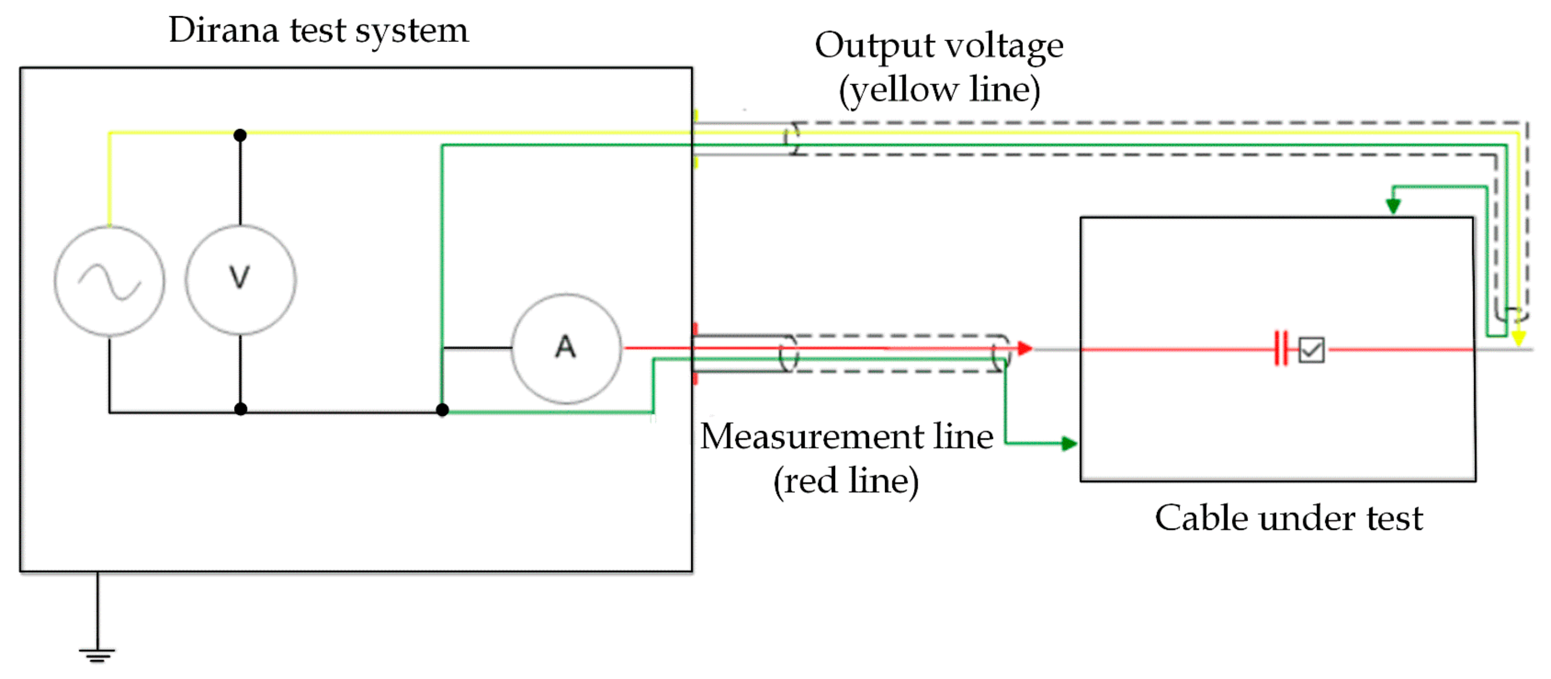
5.2. Frequency Domain Spectroscopy (FDS)
- General dielectric test type configuration;
- Output voltage: 200 V (peak-peak).
5.3. Test Conditions of Electrical Measurements
- 1.
- Virtually, electromagnetic interferences and noise affect the dielectric measurements; thus, the electrical measurements were carried out while the samples were placed inside a Faraday’s cage;
- 2.
- Floating potentials may arise in the case of multi-point grounding; therefore, the whole grounding system has been achieved via single-point grounding;
- 3.
- The test temperature was 50 °C (in the oven), and the relative humidity was approximately 10%. These test conditions, i.e., temperature and humidity, help obtain a better dielectric response as the polymers chains and charge carriers’ mobility increase at higher temperatures [7]. Moreover, the role of humidity in the measurement can be ignored.
5.4. Shore D Hardness
6. Results
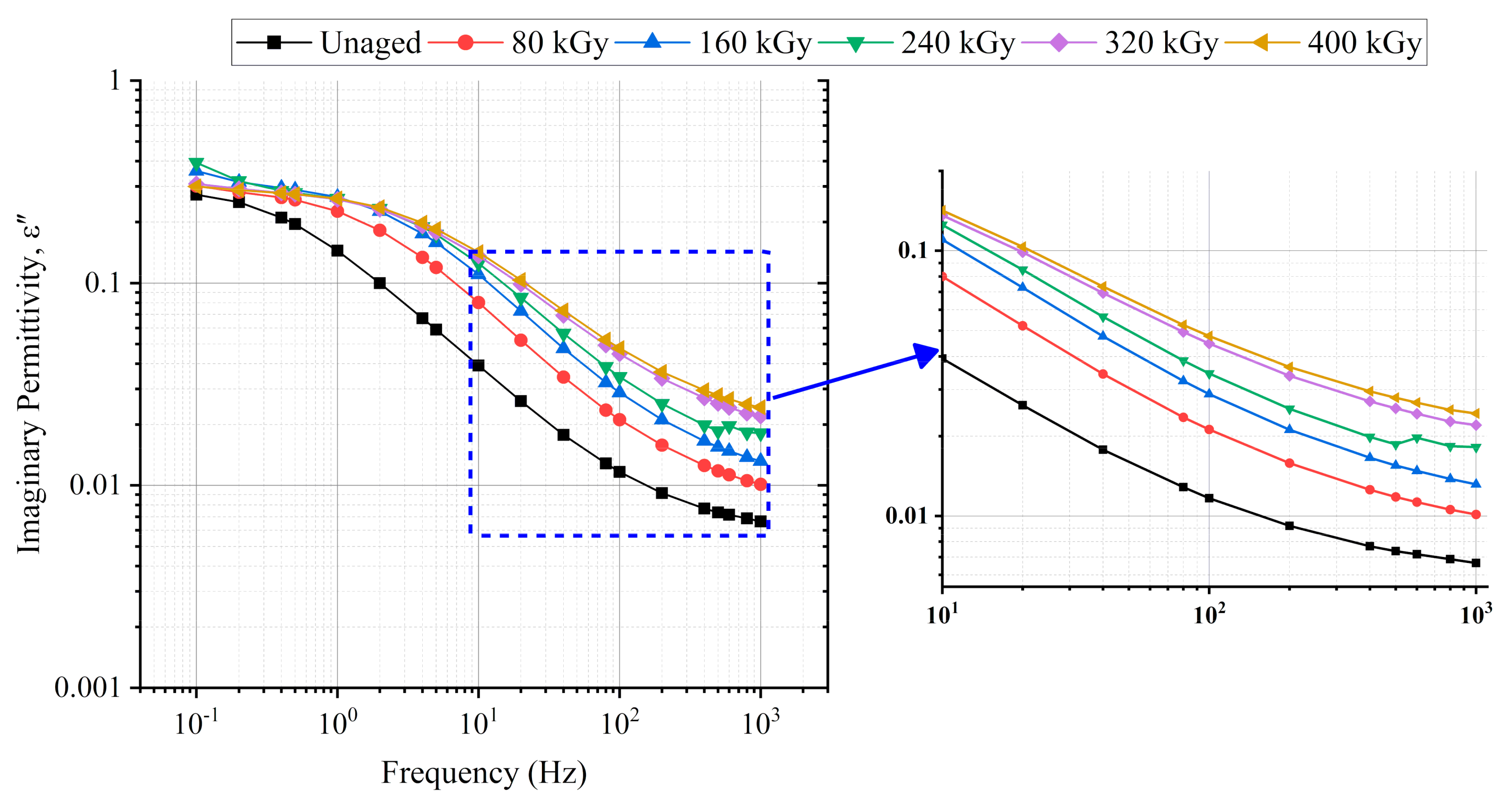
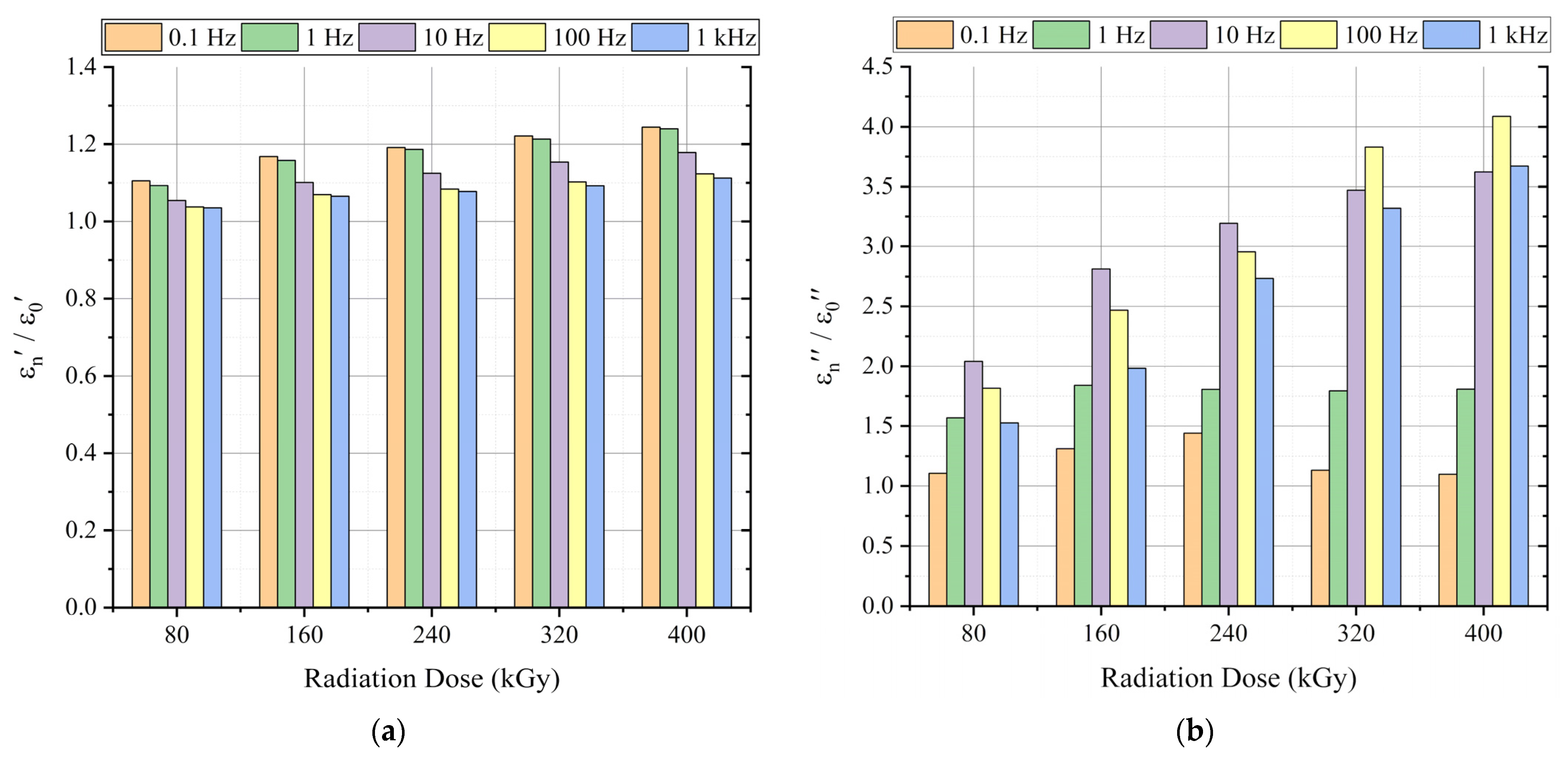
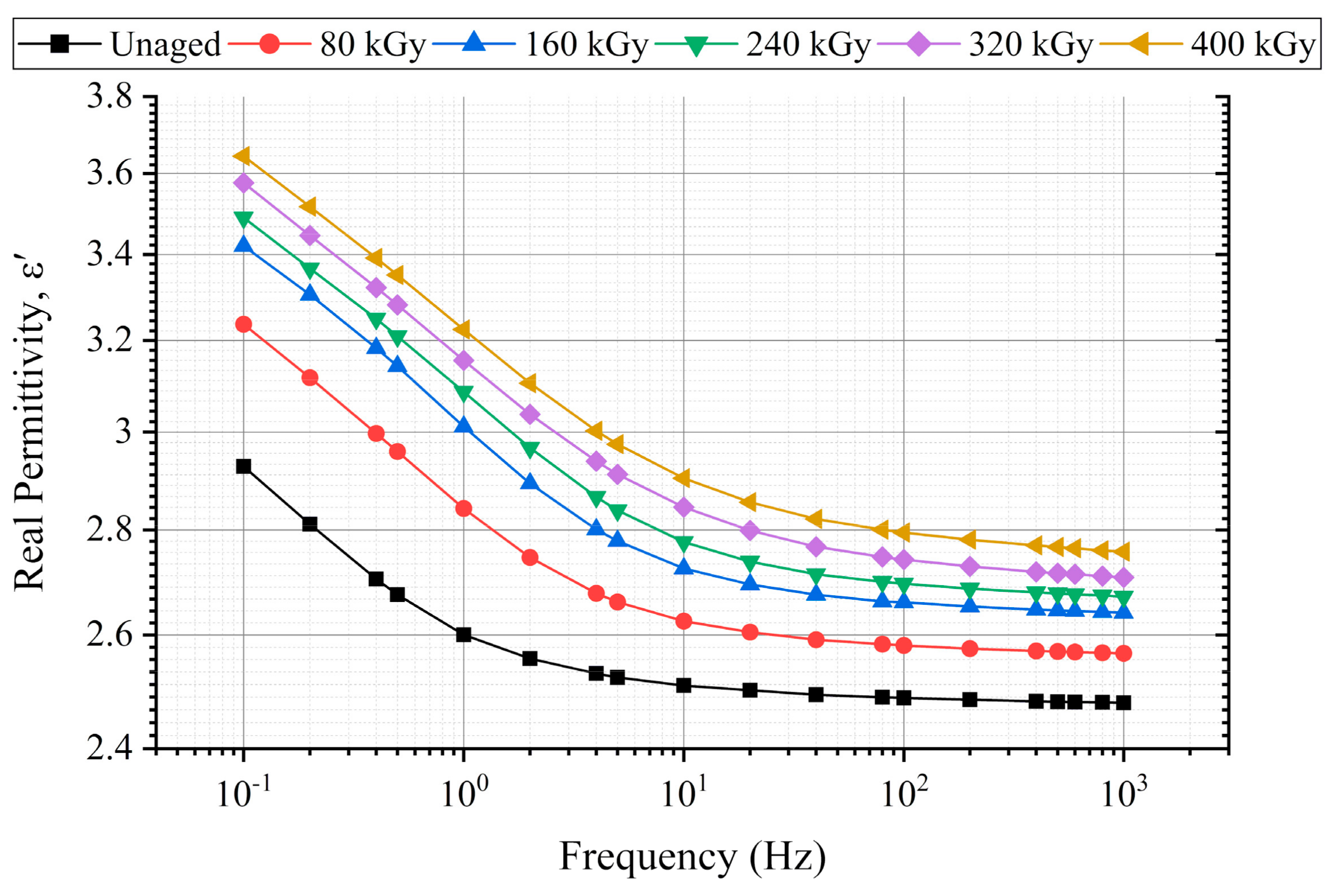
6.1. Permittivity
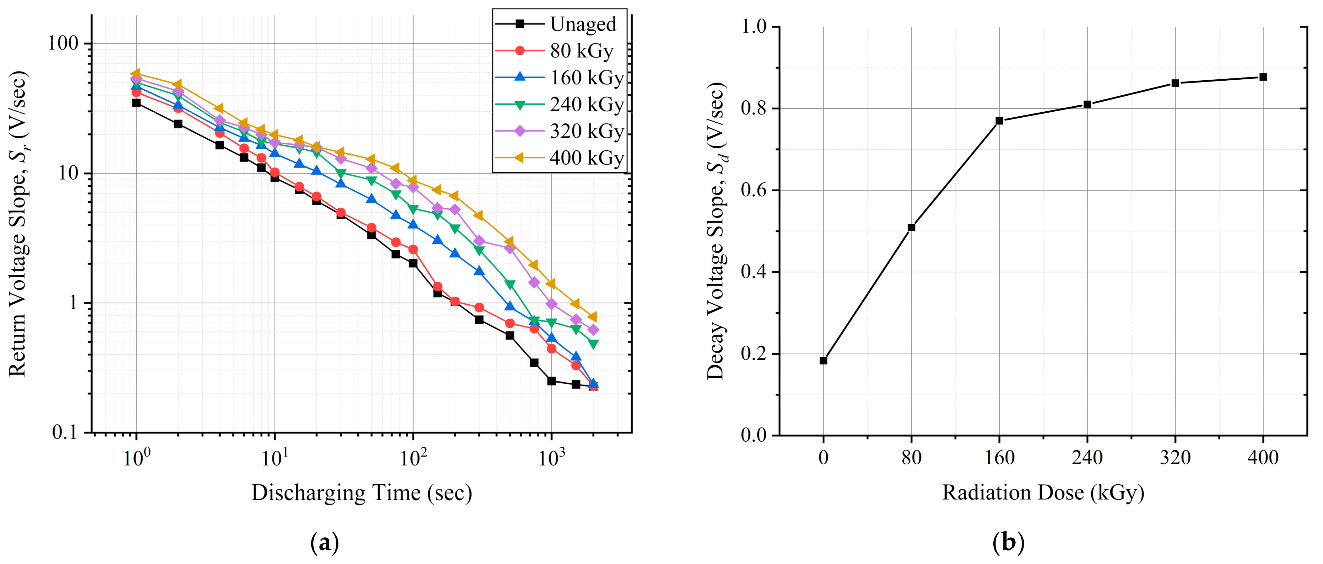
6.2. EVR
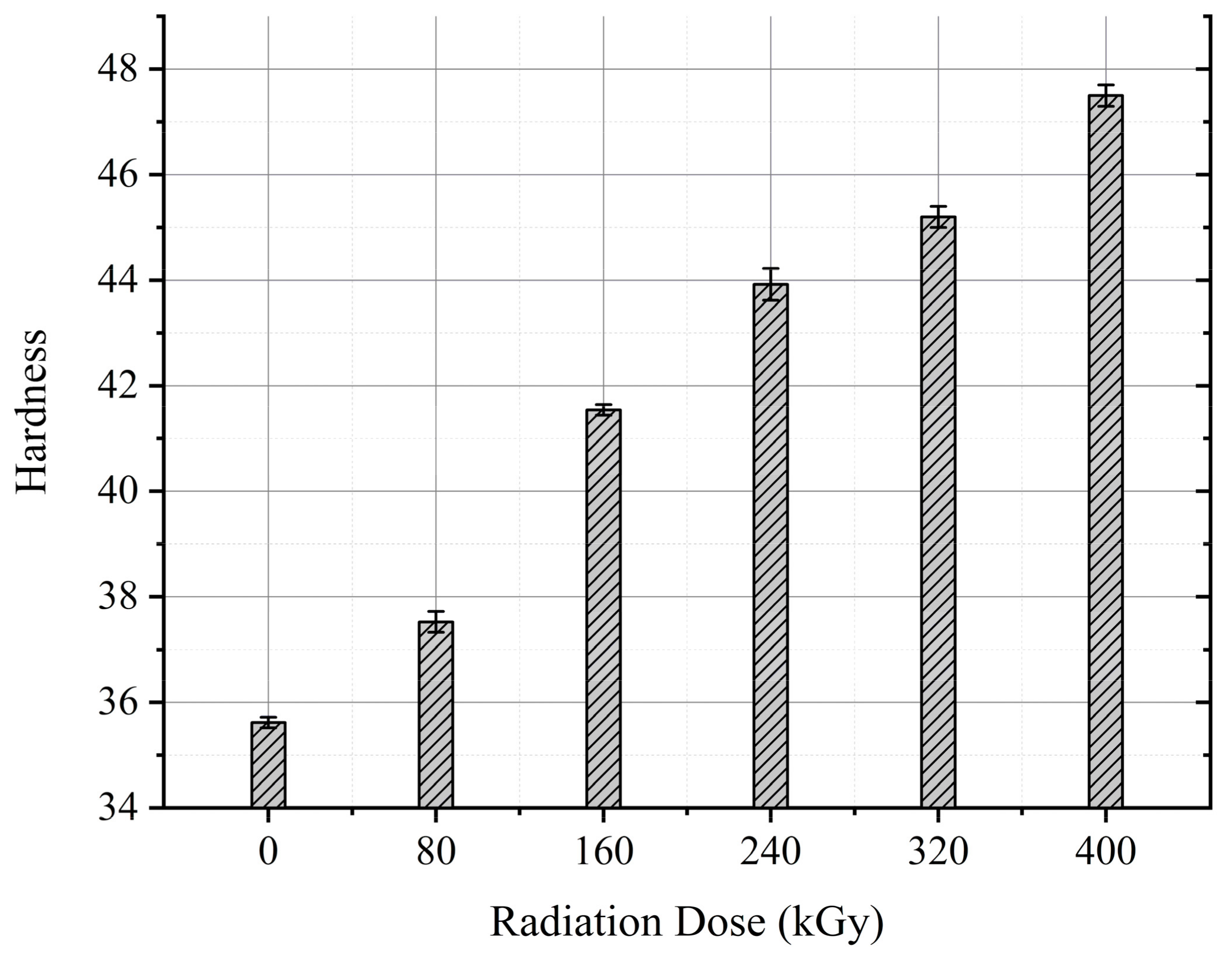
6.3. Hardness
7. Discussion
7.1. Change in Real and Imaginary Parts of Permittivity
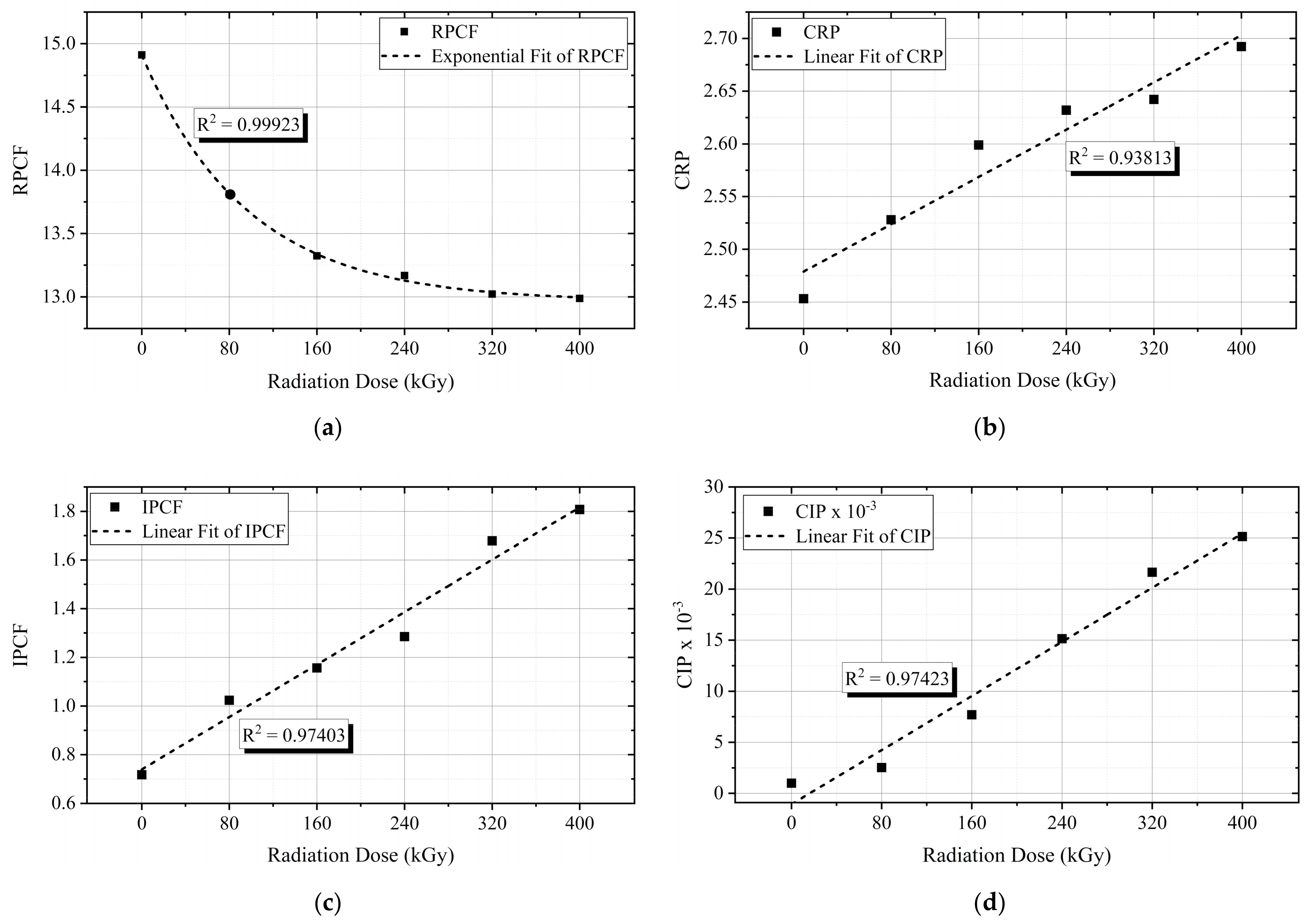
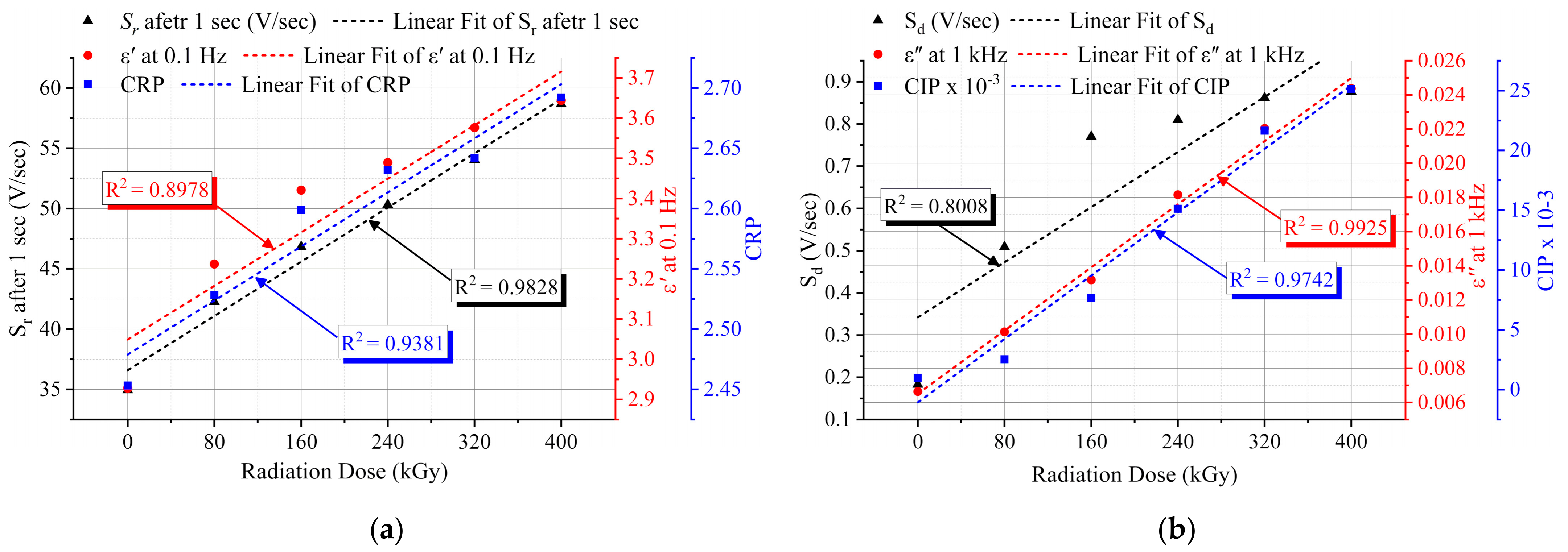
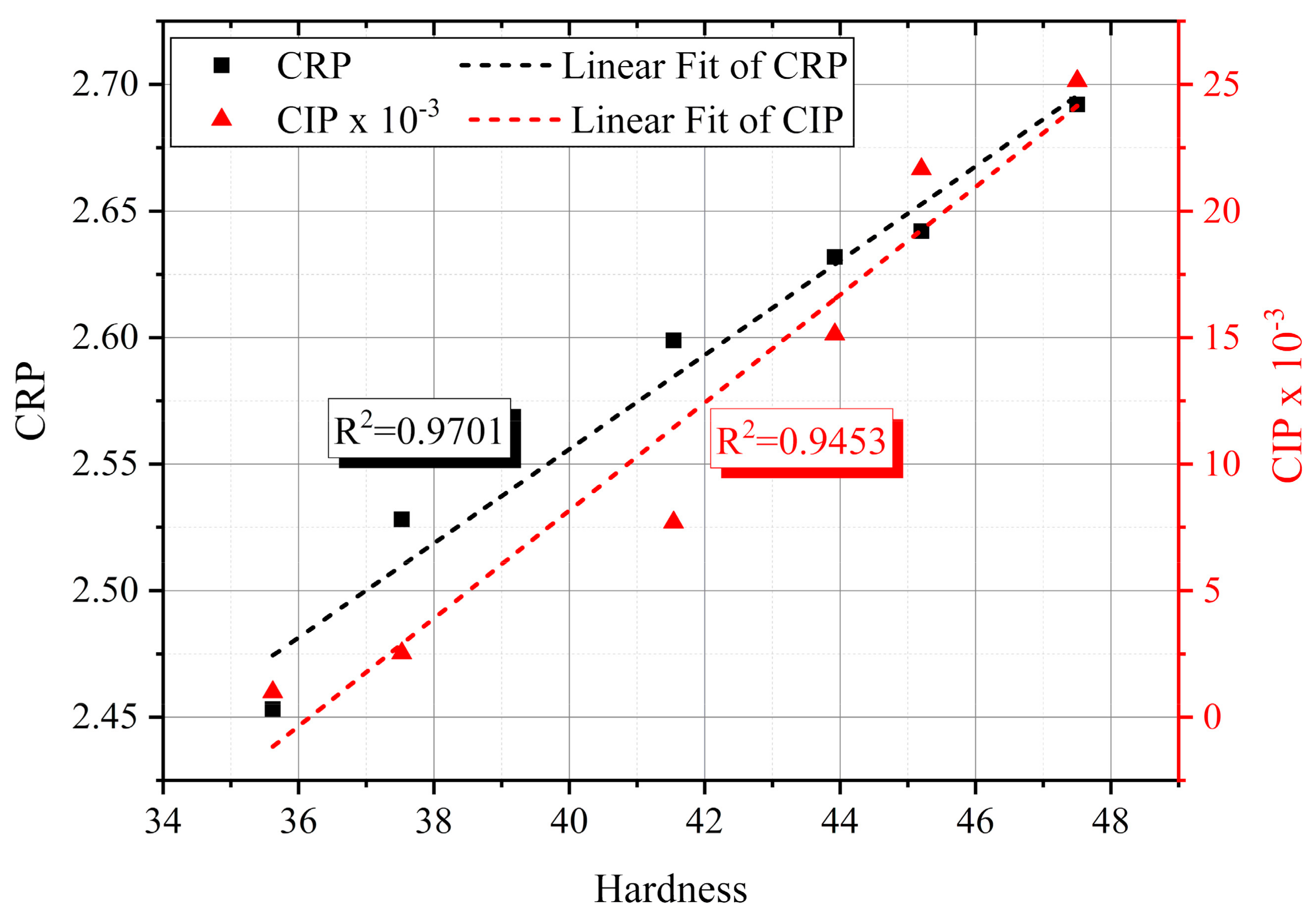
7.2. Central Frequency (CF) and Central Permittivity (CP)
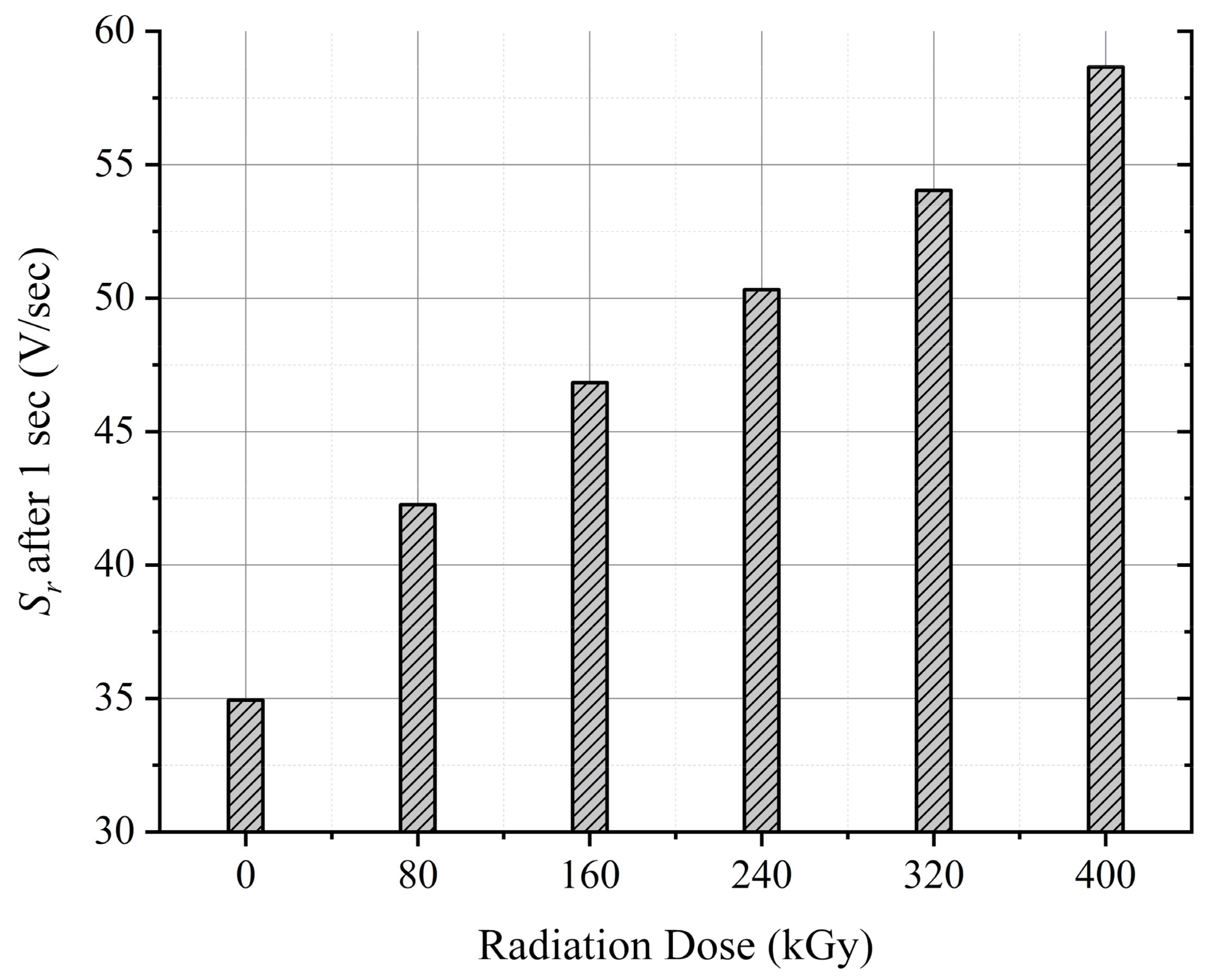
7.3. Return and Decay Voltage Slopes
7.4. Hardness
8. Non-Destructive Aging Indicators
9. Conclusions
Author Contributions
Funding
Institutional Review Board Statement
Informed Consent Statement
Data Availability Statement
Conflicts of Interest
Abbreviations
| NPP | Nuclear power plant |
| LOCA | Loss of coolant accident |
| I&C | Instrumentation and control |
| LV | Low-voltage |
| MV | Medium-voltage |
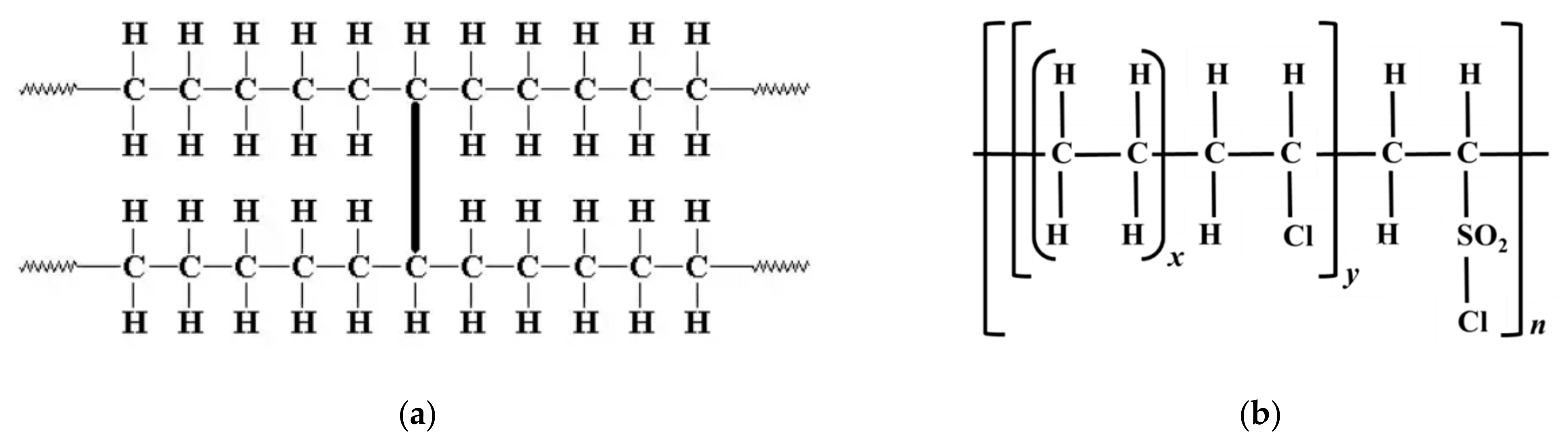
| XLPE | Cross-linked polyethylene |
| EPR | Ethylene-propylene rubber |
| CSPE | Chlorosulfonated polyethylene |
| EaB | Elongation at break |
| EVR | Extended voltage response |
| VR | Voltage response |
| PVC | Polyvinyl chloride |
| Sd | Decay voltage slope |
| Sr | Return voltage slope |
| ε′ | Real part of permittivity |
| ε″ | Imaginary part of permittivity |
| CF | Central frequency |
| CP | Central permittivity |
| CRP | Central real permittivity |
| RPCF | Real permittivity central frequency |
| CIP | Central imaginary permittivity |
| IPCF | Imaginary permittivity central frequency |
References
- Harmon, G.; Toll, T.; Sexton, C. Development and Implementation of An In-Situ Cable Condition Monitoring Method For Nuclear Power Plants. In Proceedings of the 2020 IEEE Electrical Insulation Conference (EIC), Online, 22 June 22–3 July 2020; pp. 33–36. [Google Scholar]
- Suraci, S.V.; Fabiani, D.; Xu, A.; Roland, S.; Colin, X. Ageing Assessment of XLPE LV Cables for Nuclear Applications Through Physico-Chemical and Electrical Measurements. IEEE Access 2020, 8, 27086–27096. [Google Scholar] [CrossRef]
- Toll, T.; Ward, P.; Ferree, C.; Sexton, C.; Harmon, G. Application of Cable Condition Monitoring Technologies to Assess Age-Related Degradation of Industrial Cables Installed in Harsh Environments. Nucl. Technol. 2021. [Google Scholar] [CrossRef]
- Linde, E.; Verardi, L.; Pourmand, P.; Fabiani, D.; Gedde, U. Non-destructive condition monitoring of aged ethylene-propylene copolymer cable insulation samples using dielectric spectroscopy and NMR spectroscopy. Polym. Test. 2015, 46, 72–78. [Google Scholar] [CrossRef]
- Suraci, S.V.; Fabiani, D. Aging modelling of low-voltage cables subjected to radio-chemical aging. IEEE Access 2021. [Google Scholar] [CrossRef]
- Banford, M.; Fouracre, R.A. Nuclear technology and ageing. EEE Electr. Insul. Mag. 1999, 15, 19–27. [Google Scholar] [CrossRef]
- IAEA. Benchmark Analysis for Condition Monitoring Test Techniques of Aged Low Voltage Cables in Nuclear Power Plants; Iaea-Tecdoc: Vienna, Austria, 2017; p. 179. [Google Scholar]
- Verardi, L. Aging of Nuclear Power Plant Cables: In Search of non-Destructive Diagnostic Quantities. Ph.D. Thesis, University of Bologna, Bologna, Italy, 2013. [Google Scholar]
- Sriraman, A.; Bowler, N.; Glass, S.; Fifield, L.S. Dielectric and Mechanical Behavior of Thermally Aged EPR/CPE Cable Materials. In Proceedings of the Annual Report—Electrical Insulation and Dielectric Phenomena CEIDP, Cancun, Mexico, 21–24 October 2018; Volume 2018, pp. 598–601. [Google Scholar]
- Mustafa, E.; Afia, R.S.A.; Tamus, Z.A. Application of Non-Destructive Condition Monitoring Techniques on Irradiated Low Voltage Unshielded Nuclear Power Cables. IEEE Access 2020, 8, 166024–166033. [Google Scholar] [CrossRef]
- Wang, W.C.; Liu, Y.; Guo, Y.; Ma, L.; Liu, Y.; Zhou, C.; Yu, X.; Zhao, G. Lead-free sodium bismuth halide Cs2NaBiX6 double perovskite nanocrystals with highly efficient photoluminesence. Chem. Eng. J. 2020, 397, 125367. [Google Scholar] [CrossRef]
- Wang, W.C.; Liu, Y.; Feng, X.; Zhou, C.; Liu, Y.; Yu, X.; Zhao, G. Phase Regulation Strategy of Perovskite Nanocrystals from 1D Orthomorphic NH4PbI3 to 3D Cubic (NH4)0.5Cs0.5Pb(I0.5Br0.5)3 Phase Enhances Photoluminescence. Angew. Chem. Int. Ed. 2019, 58, 11642–11646. [Google Scholar] [CrossRef]
- Glass, S.W.; Ramuhalli, P.; Fifield, L.S.; Prowant, M.S.; Dib, G.; Tedeschi, J.R.; Suter, J.D.; Jones, A.M.; Good, M.S.; Pardini, A.F.; et al. Assessment of NDE for key indicators of aging cables in nuclear power plants—Interim status. In Proceedings of the 42nd Annual Review of Progress in Quantitative Nondestructive Evaluation: Incorporating the 6th European-American Workshop on Reliability of NDE, Minneapolis, MN, USA, 26–31 July 2015; Volume 1706, p. 170006. [Google Scholar] [CrossRef]
- Fabiani, D.; Suraci, S.V.; Bulzaga, S. Aging Investigation of Low-Voltage Cable Insulation Used in Nuclear Power Plants. In Proceedings of the 2018 IEEE Electrical Insulation Conference (EIC), EIC 2018, San Antonio, TX, USA, 17–20 June 2018; pp. 516–519. [Google Scholar]
- Bowler, N.; Liu, S. Aging Mechanisms and Monitoring of Cable Polymers. Int. J. Progn. Health Manag. 2015, 6, 6. [Google Scholar] [CrossRef]
- Anandakumaran, K. Aging and condition monitoring studies of composite insulation cables used in nuclear power plants. IEEE Trans. Dielectr. Electr. Insul. 2007, 14, 227–237. [Google Scholar] [CrossRef]
- Plaček, V.; Kohout, T.; Kábrt, J.; Jiran, J. The influence of mechanical stress on cable service life-time. Polym. Test. 2011, 30, 709–715. [Google Scholar] [CrossRef]
- IAEA. Pilot Study on the Management of Ageing of Instrumentation and Control Cables. Available online: https://www.iaea.org/publications/5584/pilot-study-on-the-management-of-ageing-of-instrumentation-and-control-cables (accessed on 3 March 2021).
- Suraci, S.V.; Fabiani, D. Quantitative investigation and modelling of the electrical response of XLPE insulation with different filler content. In Proceedings of the 2020 IEEE Conference on Electrical Insulation and Dielectric Phenomena (CEIDP), Cancun, Mexico, 21–24 October 2020; pp. 439–442. [Google Scholar]
- Suraci, S.V.; Fabiani, D.; Li, C. Additive effect on dielectric spectra of cross-linked polyethylene (XLPE) used in nuclear power plants. In Proceedings of the 2019 IEEE Electrical Insulation Conference, EIC 2019, Calgary, AL, Canada, 16–19 June 2019; pp. 410–413. [Google Scholar]
- Subudhi, M. Literature Review of Environmental Qualification of Safety-Related Electric Cables: Summary of Past Work; Brookhaven National Laboratory: Upton, NY, USA, 1996; Volume 1, pp. 1–306. [Google Scholar]
- Afia, R.S.A.; Mustafa, E.; Tamus, Z.A. Mechanical Stresses on Polymer Insulating Materials. In Proceedings of the 2018 International Conference on Diagnostics in Electrical Engineering (Diagnostika), Pilsen, Czech Republic, 4–7 September 2018; pp. 1–4. [Google Scholar] [CrossRef]
- Institute of Electrical and Electronics Engineers IEEE Standard for Qualifying Electric Cables and Splices for Nuclear Facilities; IEEE: New York, NY, USA, 2015; Volume IEEE 383-2015.
- Anandakumaran, K.; Seidl, W.; Castaldo, P. Condition assessment of cable insulation systems in operating nuclear power plants. IEEE Trans. Dielectr. Electr. Insul. 1999, 6, 376–384. [Google Scholar] [CrossRef]
- Initial Acceptance Criteria Concepts and Data for Assessing Longevity of Low-Voltage Cable Insulations and Jackets. Available online: https://www.epri.com/research/products/1008211 (accessed on 6 September 2020).
- Afia, R.S.A.; Ehtasham, M.; Tamus, Z.A. Electrical and Mechanical Condition Assessment of Low Voltage Unshielded Nuclear Power Cables under Simultaneous Thermal and Mechanical Stresses: Application of Non-Destructive Test Techniques. IEEE Access 2021, 9, 4531–4541. [Google Scholar] [CrossRef]
- Fabiani, D.; Suraci, S. Broadband Dielectric Spectroscopy: A Viable Technique for Aging Assessment of Low-Voltage Cable Insulation Used in Nuclear Power Plants. Polymers 2021, 13, 494. [Google Scholar] [CrossRef]
- Tamus, Z.Á.; Németh, E. Condition Assessment of PVC Insulated Low Voltage Cables by Voltage Response Method. Int. Conf. Cond. Monit. Diagn. 2010, 721–724. [Google Scholar]
- Gao, Y.; Du, B. Effect of gamma-ray irradiation on permittivity and dielectric loss of polymer insulating materials. In Proceedings of the 2012 International Conference on High Voltage Engineering and Application, Shanghai, China, 17–20 September 2012; pp. 229–232. [Google Scholar]
- Linde, E.; Verardi, L.; Fabiani, D.; Gedde, U. Dielectric spectroscopy as a condition monitoring technique for cable insulation based on crosslinked polyethylene. Polym. Test. 2015, 44, 135–142. [Google Scholar] [CrossRef]
- Chand, N.; Fahim, M. Wood-reinforced polymer composites. Tribol. Nat. Fiber Polym. Compos. 2021, 177–191. [Google Scholar] [CrossRef]
- Gillen, K.T.; Assink, R.; Bernstein, R.; Celina, M. Condition monitoring methods applied to degradation of chlorosulfonated polyethylene cable jacketing materials. Polym. Degrad. Stab. 2006, 91, 1273–1288. [Google Scholar] [CrossRef]
- Tamus, Z.Á.; Szirmai, Á.; Nemeth, B. Comparison of voltage response and return voltage measurements of a transformer insulation model. In Proceedings of the 19th International Symposium High Voltage Energy, Pilsen, Czech Republic, 23–28 August 2015. [Google Scholar]
- Tamus, Z.Á.; Csábi, D.; Csányi, G.M. Characterization of dielectric materials by the extension of voltage response method. J. Physics Conf. Ser. 2015, 646, 012043. [Google Scholar] [CrossRef]
- Crine, J.-P. Influence of electro-mechanical stress on electrical properties of dielectric polymers. IEEE Trans. Dielectr. Electr. Insul. 2005, 12, 791–800. [Google Scholar] [CrossRef]
- Jonscher, A.K.; Lacoste, R. On a Cumulative Model of Dielectric Breakdown in Solids. IEEE Trans. Electr. Insul. 1984, EI-19, 567–577. [Google Scholar] [CrossRef]
- Du, B.X.; Su, J.G.; Li, J.; Han, T. Effects of mechanical stress on treeing growth characteristics in HTV silicone rubber. IEEE Trans. Dielectr. Electr. Insul. 2017, 24, 1547–1556. [Google Scholar] [CrossRef]
- Salam, M.A.-E.; El-Gamal, S.; El-Maqsoud, D.A.; Mohsen, M. Correlation of electrical and swelling properties with nano free-volume structure of conductive silicone rubber composites. Polym. Compos. 2013, 34, 2105–2115. [Google Scholar] [CrossRef]
- Burnay, S.G.; Dawson, J. Reverse Temperature Effect During Radiation Ageing of XLPE Cable Insulation. Ageing Stud. Lifetime Ext. Mater. 2001, 493–497. [Google Scholar] [CrossRef]
- Suraci, S.V.; Fabiani, D.; Li, C. Post-irradiation effect analysis on XLPE-insulated LV cables used in nuclear power plants. In Proceedings of the 2019 2nd International Conference on Electrical Materials and Power Equipment (ICEMPE), Guangzhou, China, 7–10 April 2019; pp. 53–56. [Google Scholar] [CrossRef]
- Suljovrujic, E. Post-irradiation effects in polyethylenes irradiated under various atmospheres. Radiat. Phys. Chem. 2013, 89, 43–50. [Google Scholar] [CrossRef]
- Da Cruz, M.; Van Schoors, L.; Benzarti, K.; Colin, X. Thermo-oxidative degradation of additive free polyethylene. Part I. Analysis of chemical modifications at molecular and macromolecular scales. J. Appl. Polym. Sci. 2016, 133, 133. [Google Scholar] [CrossRef]
- Csányi, G.M.; Bal, S.; Tamus, Z. Ádám Dielectric Measurement Based Deducted Quantities to Track Repetitive, Short-Term Thermal Aging of Polyvinyl Chloride (PVC) Cable Insulation. Polymers 2020, 12, 2809. [Google Scholar] [CrossRef]
- Afia, R.S.; Mustafa, E.; Tamus, Z. Ádám Dielectric Spectroscopy of Low Voltage Nuclear Power Cables Under Simultaneous Thermal and Mechanical Stresses. Energy Rep. 2020, 6, 662–667. [Google Scholar] [CrossRef]


| Parameter | Value |
|---|---|
| Cable type | Single-core unshielded |
| Nominal voltage (kV) | 0.6 |
| Conductor size (AWG) | 6 |
| Number of strands | 7 |
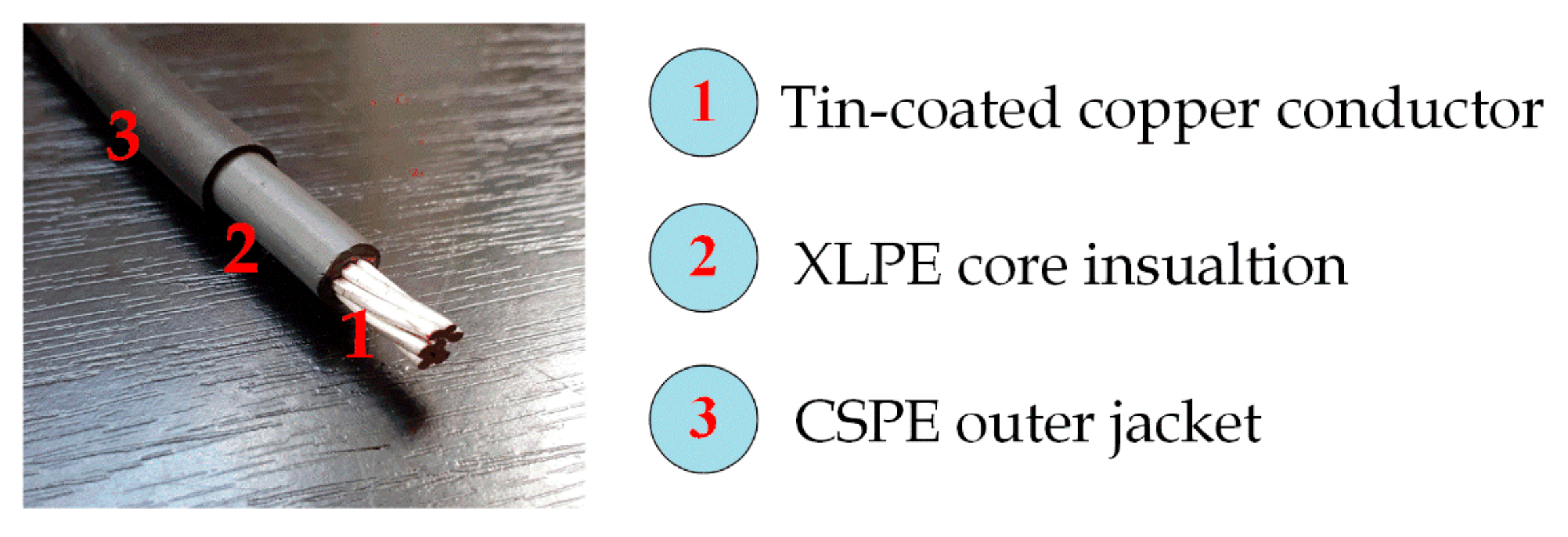
| Core insulation | XLPE |
| Insulation thickness (Mils) | 45 |
| Jacket material | CSPE |
| Jacket thickness (Mils) | 30 |
| Overall diameter (inch) | 0.34 |
| Bend radius permanent training (inch) | 1.5 |
| Bend radius during installation (inch) | 2.75 |
| Max. conductor temperature (°C) | 120 |
Publisher’s Note: MDPI stays neutral with regard to jurisdictional claims in published maps and institutional affiliations. |
© 2021 by the authors. Licensee MDPI, Basel, Switzerland. This article is an open access article distributed under the terms and conditions of the Creative Commons Attribution (CC BY) license (https://creativecommons.org/licenses/by/4.0/).
Share and Cite
Afia, R.S.A.; Mustafa, E.; Tamus, Z.Á. Aging Mechanisms and Non-Destructive Aging Indicators of XLPE/CSPE Unshielded LV Nuclear Power Cables Subjected to Simultaneous Radiation-Mechanical Aging. Polymers 2021, 13, 3033. https://doi.org/10.3390/polym13183033
Afia RSA, Mustafa E, Tamus ZÁ. Aging Mechanisms and Non-Destructive Aging Indicators of XLPE/CSPE Unshielded LV Nuclear Power Cables Subjected to Simultaneous Radiation-Mechanical Aging. Polymers. 2021; 13(18):3033. https://doi.org/10.3390/polym13183033
Chicago/Turabian StyleAfia, Ramy S. A., Ehtasham Mustafa, and Zoltán Ádám Tamus. 2021. "Aging Mechanisms and Non-Destructive Aging Indicators of XLPE/CSPE Unshielded LV Nuclear Power Cables Subjected to Simultaneous Radiation-Mechanical Aging" Polymers 13, no. 18: 3033. https://doi.org/10.3390/polym13183033
APA StyleAfia, R. S. A., Mustafa, E., & Tamus, Z. Á. (2021). Aging Mechanisms and Non-Destructive Aging Indicators of XLPE/CSPE Unshielded LV Nuclear Power Cables Subjected to Simultaneous Radiation-Mechanical Aging. Polymers, 13(18), 3033. https://doi.org/10.3390/polym13183033