
A Negative Index Nonagonal CSRR Metamaterial-Based Compact Flexible Planar Monopole Antenna for Ultrawideband Applications Using Viscose-Wool Felt

 ,
,  ,
,  ,
,  ,
,  ,
,  ,
,  and
and 
Abstract
1. Introduction
2. Flexible Polymer-Based Textile Antenna Design with Metamaterial
2.1. Metamaterial Design
2.2. Metamaterial Working Principle
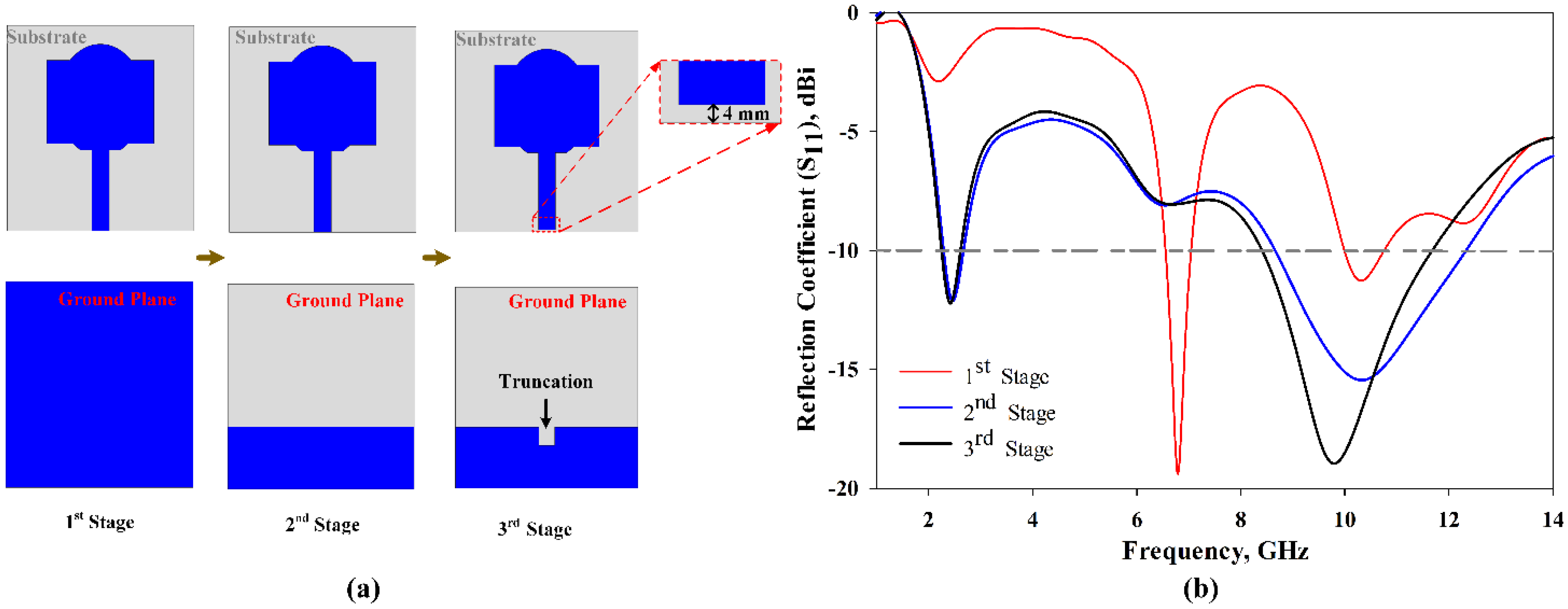
2.3. Antenna Design Geometry and Configurations
3. Results and Discussion
4. Conclusions
Author Contributions
Funding
Institutional Review Board Statement
Informed Consent Statement
Data Availability Statement
Conflicts of Interest
References
- Ali Khan, M.U.; Raad, R.; Tubbal, F.; Theoharis, P.I.; Liu, S.; Foroughi, J. Bending Analysis of Polymer-Based Flexible Antennas for Wearable, General IoT Applications: A Review. Polymers 2021, 13, 357. [Google Scholar] [CrossRef]
- Kirtania, S.G.; Elger, A.W.; Hasan, M.R.; Wisniewska, A.; Sekhar, K.; Karacolak, T.; Sekhar, P.K. Flexible Antennas: A Review. Micromachines 2020, 11, 847. [Google Scholar] [CrossRef] [PubMed]
- Farooq, S.; Tahir, A.A.; Krewer, U.; Shah, A.U.H.A.; Bilal, S. Efficient photocatalysis through conductive polymer coated FTO counter electrode in platinum free dye sensitized solar cells. Electrochim. Acta 2019, 320, 134544. [Google Scholar] [CrossRef]
- Rahman, S.U.; Bilal, S.; ul Haq Ali Shah, A. Synthesis and Characterization of Polyaniline-Chitosan Patches with Enhanced Stability in Physiological Conditions. Polymers 2020, 12, 2870. [Google Scholar] [CrossRef]
- Rahman, S.U.; Röse, P.; Surati, M.; Shah, A.U.H.A.; Krewer, U.; Bilal, S. 3D Polyaniline Nanofibers Anchored on Carbon Paper for High-Performance and Light-Weight Supercapacitors. Polymers 2020, 12, 2705. [Google Scholar] [CrossRef] [PubMed]
- ur Rahman, S.; Röse, P.; ul Haq Ali Shah, A.; Krewer, U.; Bilal, S. An Amazingly Simple, Fast and Green Synthesis Route to Polyaniline Nanofibers for Efficient Energy Storage. Polymers 2020, 12, 2212. [Google Scholar] [CrossRef]
- Ur Rahman, S.; Röse, P.; ul Haq Ali Shah, A.; Krewer, U.; Bilal, S.; Farooq, S. Exploring the Functional Properties of Sodium Phytate Doped Polyaniline Nanofibers Modified FTO Electrodes for High-Performance Binder Free Symmetric Supercapacitors. Polymers 2021, 13, 2329. [Google Scholar] [CrossRef]
- Bibi, S.; Ullah, H.; Ahmad, S.M.; Ali Shah, A.-H.; Bilal, S.; Tahir, A.A.; Ayub, K. Molecular and Electronic Structure Elucidation of Polypyrrole Gas Sensors. J. Phys. Chem. C 2015, 119, 15994–16003. [Google Scholar] [CrossRef]
- Zia, T.U.H.; Ali Shah, A.U.H. Understanding the adsorption of 1 NLB antibody on polyaniline nanotubes as a function of zeta potential and surface charge density for detection of hepatitis C core antigen: A label-free impedimetric immunosensor. Colloids Surfaces A Physicochem. Eng. Asp. 2021, 626, 127076. [Google Scholar] [CrossRef]
- Jiang, X.; Xu, C.; Gao, T.; Bando, Y.; Golberg, D.; Dai, P.; Hu, M.; Ma, R.; Hu, Z.; Wang, X.-B. Flexible conductive polymer composite materials based on strutted graphene foam. Compos. Commun. 2021, 25, 100757. [Google Scholar] [CrossRef]
- Zhou, K.; Dai, K.; Liu, C.; Shen, C. Flexible conductive polymer composites for smart wearable strain sensors. SmartMat 2020, 1, 1–5. [Google Scholar] [CrossRef]
- Mohamadzade, B.; Hashmi, R.M.; Simorangkir, R.B.V.B.; Gharaei, R.; Ur Rehman, S.; Abbasi, Q.H. Recent Advances in Fabrication Methods for Flexible Antennas in Wearable Devices: State of the Art. Sensors 2019, 19, 2312. [Google Scholar] [CrossRef]
- Jamshaid, H.; Mishra, R.; Zeeshan, M.; Zahid, B.; Basra, S.A.; Tichy, M.; Muller, M. Mechanical Performance of Knitted Hollow Composites from Recycled Cotton and Glass Fibers for Packaging Applications. Polymers 2021, 13, 2381. [Google Scholar] [CrossRef] [PubMed]
- Commission, F.C. FCC Report and Order for Part 15 Acceptance of Ultra Wideband (UWB) Systems from 3.1–10.6 GHz; FCC: Washington, DC, USA, 2002; pp. 1–10. [Google Scholar]
- Samal, P.B.; Soh, P.J.; Zakaria, Z. Compact Microstrip-Based Textile Antenna for 802.15.6 WBAN-UWB with Full Ground Plane. Int. J. Antennas Propag. 2019, 2019, 1–12. [Google Scholar] [CrossRef]
- Samal, P.B.; Soh, P.J.; Xu, H.; Vandenbosch, G.A.E. Microstrip-based all-textile unidirectional UWB antenna with full ground plane. In Proceedings of the 8th European Conference on Antennas and Propagation, EuCAP 2014, Hague, The Netherlands, 6–11 April 2014; pp. 1408–1412. [Google Scholar] [CrossRef]
- Yalduz, H.; Koç, B.; Kuzu, L.; Turkmen, M. An ultra-wide band low-SAR flexible metasurface-enabled antenna for WBAN applications. Appl. Phys. A Mater. Sci. Process. 2019, 125, 1–11. [Google Scholar] [CrossRef]
- Gao, G.P.; Hu, B.; Wang, S.F.; Yang, C. Wearable Circular Ring Slot Antenna with EBG Structure for Wireless Body Area Network. IEEE Antennas Wirel. Propag. Lett. 2018, 17, 434–437. [Google Scholar] [CrossRef]
- Tian, X.; Lee, P.M.; Tan, Y.J.; Wu, T.L.Y.; Yao, H.; Zhang, M.; Li, Z.; Ng, K.A.; Tee, B.C.K.; Ho, J.S. Wireless body sensor networks based on metamaterial textiles. Nat. Electron. 2019, 2, 243–251. [Google Scholar] [CrossRef]
- Moradi, B.; Fernández-García, R.; Gil, I. E-Textile Embroidered Metamaterial Transmission Line for Signal Propagation Control. Materials 2018, 11, 955. [Google Scholar] [CrossRef]
- Zhang, K.; Soh, P.J.; Yan, S. Meta-Wearable Antennas—A Review of Metamaterial Based Antennas in Wireless Body Area Networks. Materials 2020, 14, 149. [Google Scholar] [CrossRef]
- Wu, J.F.; Qiu, C.; Wang, Y.; Zhao, R.; Cai, Z.P.; Zhao, X.G.; He, S.S.; Wang, F.; Wang, Q.; Li, J.Q. Human limb motion detection with novel flexible capacitive angle sensor based on conductive textile. Electronics 2018, 7, 192. [Google Scholar] [CrossRef]
- Tartare, G.; Zeng, X.; Koehl, L. Development of a wearable system for monitoring the firefighter’s physiological state. In Proceedings of the 2018 IEEE Industrial Cyber-Physical Systems ICPS 2018, St. Petersburg, Russia, 15–18 May 2018; pp. 561–566. [Google Scholar] [CrossRef]
- Saenz-Cogollo, J.F.; Pau, M.; Fraboni, B.; Bonfiglio, A. Pressure mapping mat for tele-home care applications. Sensors 2016, 16, 365. [Google Scholar] [CrossRef]
- Gric, T.; Hess, O. Metamaterial Cloaking. In Phenomena of Optical Metamaterials; Gric, T., Hess, O., Eds.; Elsevier: Amsterdam, The Netherlands, 2019; pp. 175–186. ISBN 9780128138960. [Google Scholar]
- Ahdi Rezaeieh, S.; Antoniades, M.A.; Abbosh, A.M. Gain Enhancement of Wideband Metamaterial-Loaded Loop Antenna with Tightly Coupled Arc-Shaped Directors. IEEE Trans. Antennas Propag. 2017, 65, 2090–2095. [Google Scholar] [CrossRef]
- Islam, M.M.T.; Islam, M.M.T.; Samsuzzaman, M.; Faruque, M.R.I. Compact metamaterial antenna for UWB applications. Electron. Lett. 2015, 51, 1222–1224. [Google Scholar] [CrossRef]
- Al-Bawri, S.S.; Hwang Goh, H.; Islam, M.S.; Wong, H.Y.; Jamlos, M.F.; Narbudowiczm, A.; Jusoh, M.; Sabapathy, T.; Khan, R.; Islam, M.T. Compact Ultra-Wideband Monopole Antenna Loaded with Metamaterial. Sensors 2020, 20, 796. [Google Scholar] [CrossRef] [PubMed]
- Khandelwal, M.K.; Arora, A.; Kumar, S.; Kim, K.W.; Choi, H.C. Dual band double negative (DNG) metamaterial with small frequency ratio. J. Electromagn. Waves Appl. 2018, 32, 2167–2181. [Google Scholar] [CrossRef]
- Singh, H.; Sohi, B.S.; Gupta, A. A compact CRLH metamaterial with wide band negative index characteristics. Bull. Mater. Sci. 2019, 42, 1–11. [Google Scholar] [CrossRef]
- Islam, S.S.; Iqbal Faruque, M.R.; Islam, M.T. Design and absorption analysis of a new multiband split-S-shaped metamaterial. Sci. Eng. Compos. Mater. 2017, 24, 139–148. [Google Scholar] [CrossRef]
- Hossain, K.; Sabapathy, T.; Jusoh, M.; Soh, P.J.; Osman, M.N.; Al-Bawri, S.S. A Compact Wideband CSRR Near Zero Refractive Index and Epsilon Negative Metamaterial for Wearable Microwave Applications. J. Phys. Conf. Ser. 2021, 1962, 012019. [Google Scholar] [CrossRef]
- Alemaryeen, A.; Noghanian, S. Crumpling effects and specific absorption rates of flexible AMC integrated antennas. IET Microw. Antennas Propag. 2018, 12, 627–635. [Google Scholar] [CrossRef]
- Mersani, A.; Osman, L.; Ribero, J.M. Flexible UWB AMC antenna for early stage skin cancer identification. Prog. Electromagn. Res. M 2019, 80, 71–81. [Google Scholar] [CrossRef]
- Islam, M.M.; Islam, M.T.; Faruque, M.R.I.; Samsuzzaman, M.; Misran, N.; Arshad, H. Microwave imaging sensor using compact metamaterial UWB antenna with a high correlation factor. Materials 2015, 8, 4631–4651. [Google Scholar] [CrossRef]
- Hossain, K.; Sabapathy, T.; Jusoh, M.; Soh, P.J.; Jamaluddin, M.H.; Al-Bawri, S.S.; Osman, M.N.; Ahmad, R.B.; Rahim, H.A.; Mohd Yasin, M.N.; et al. Electrically Tunable Left-Handed Textile Metamaterial for Microwave Applications. Materials 2021, 14, 1274. [Google Scholar] [CrossRef]
- Wang, F.; Arslan, T. A wearable ultra-wideband monopole antenna with flexible artificial magnetic conductor. In Proceedings of the 2016 Loughborough Antennas & Propagation Conference LAPC 2016, Loughborough, UK, 14–15 November 2016; pp. 3–7. [Google Scholar] [CrossRef]
- Gogikar, S.; Chilukuri, S. A Compact Wearable Textile Antenna with Dual Band-Notched Characteristics for UWB Applications. In Proceedings of the 2019 9th IEEE-APS Topical Conference on Antennas and Propagation in Wireless Communications APWC 2019, Granada, Spain, 9–13 September 2019; 94, pp. 426–430. [Google Scholar] [CrossRef]
- Elwi, T.A. Novel UWB printed metamaterial microstrip antenna based organic substrates for RF-energy harvesting applications. AEU Int. J. Electron. Commun. 2019, 101, 44–53. [Google Scholar] [CrossRef]
- Negi, D.; Khanna, R.; Kaur, J. Design and performance analysis of a conformal CPW fed wideband antenna with Mu-Negative metamaterial for wearable applications. Int. J. Microw. Wirel. Technol. 2019, 11, 806–820. [Google Scholar] [CrossRef]
- Sabapathy, T.; Soh, P.J.; Jusoh, M. A Three-Year Improvement Assessment of Project-Based Learning for an Antennas and Propagation Course [Education Corner]. IEEE Antennas Propag. Mag. 2020, 62, 76–84. [Google Scholar] [CrossRef]
- Hossain, T.M.; Jamlos, M.A.F.; Jamlos, M.A.F.; Soh, P.J.; Islam, M.I.; Khan, R. Modified H-shaped DNG metamaterial for multiband microwave application. Appl. Phys. A Mater. Sci. Process. 2018, 124, 183. [Google Scholar] [CrossRef]
- Baena, J.D.; Bonache, J.; Martín, F.; Sillero, R.M.; Falcone, F.; Lopetegi, T.; Laso, M.A.G.; García-García, J.; Gil, I.; Portillo, M.F.; et al. Equivalent-circuit models for split-ring resonators and complementary split-ring resonators coupled to planar transmission lines. IEEE Trans. Microw. Theory Tech. 2005, 53, 1451–1460. [Google Scholar] [CrossRef]
- Dong, Y.; Toyao, H.; Itoh, T. Design and characterization of miniaturized patch antennas loaded with complementary split-ring resonators. IEEE Trans. Antennas Propag. 2012, 60, 772–785. [Google Scholar] [CrossRef]
- Chen, X.; Grzegorczyk, T.M.; Wu, B.I.; Pacheco, J.; Kong, J.A. Robust method to retrieve the constitutive effective parameters of metamaterials. Phys. Rev. E Stat. Physics Plasmas Fluids Relat. Interdiscip. Top. 2004, 70, 7. [Google Scholar] [CrossRef]
- Islam, S.S.; Faruque, M.R.I.; Islam, M.T. A new direct retrieval method of refractive index for the metamaterial. Curr. Sci. 2015, 109, 337–342. [Google Scholar]
- Hossain, K.; Sabapathy, T.; Jusoh, M.; Soh, P.J.; Fazilah, A.F.M.; Halim, A.A.A.; Raghava, N.S.; Podilchak, S.K.; Schreurs, D.; Abbasi, Q.H. ENG and NZRI Characteristics of Decagonal-Shaped Metamaterial for Wearable Applications. In Proceedings of the 2020 International Conference on UK-China Emerging Technologies (UCET), Glasgow, UK, 20–21 August 2020; pp. 1–4. [Google Scholar]
- Moradikordalivand, A.; Rahman, T.A.; Ebrahimi, S.; Hakimi, S. An equivalent circuit model for broadband modified rectangular microstrip-fed monopole antenna. Wirel. Pers. Commun. 2014, 77, 1363–1375. [Google Scholar] [CrossRef]
- Wang, Y.; Li, J.Z.; Ran, L.X. An equivalent circuit modeling method for ultra-wideband antennas. Prog. Electromagn. Res. 2008, 82, 433–445. [Google Scholar] [CrossRef][Green Version]
- Balanis, C.A. Antenna Theory: Analysis and Design; John Wiley & Sons, 2016; ISBN 1118642066. [Google Scholar]
- Navarro-Cía, M.; Beruete, M.; Agrafiotis, S.; Falcone, F.; Sorolla, M.; Maier, S.A. Broadband spoof plasmons and subwavelength electromagnetic energy confinement on ultrathin metafilms. Opt. Express 2009, 17, 18184. [Google Scholar] [CrossRef] [PubMed]
- Huang, X.; Leng, T.; Zhang, X.; Chen, J.C.; Chang, K.H.; Geim, A.K.; Novoselov, K.S.; Hu, Z. Binder-free highly conductive graphene laminate for low cost printed radio frequency applications. Appl. Phys. Lett. 2015, 106, 203105. [Google Scholar] [CrossRef]
- Sayem, A.S.M.; Simorangkir, R.B.V.B.; Esselle, K.P.; Hashmi, R.M. Development of Robust Transparent Conformal Antennas Based on Conductive Mesh-Polymer Composite for Unobtrusive Wearable Applications. IEEE Trans. Antennas Propag. 2019, 67, 7216–7224. [Google Scholar] [CrossRef]
- Corchia, L.; Monti, G.; Tarricone, L. Durability of Wearable Antennas Based on Nonwoven Conductive Fabrics: Experimental Study on Resistance to Washing and Ironing. Int. J. Antennas Propag. 2018, 2018, 1–8. [Google Scholar] [CrossRef]
- Guo, Z.; Tian, H.; Wang, X.; Luo, Q.; Ji, Y. Bandwidth enhancement of monopole uwb antenna with new slots and ebg structures. IEEE Antennas Wirel. Propag. Lett. 2013, 12, 1550–1553. [Google Scholar] [CrossRef]
- Bialkowski, M.E.; Razali, A.R.; Boldaji, A. Design of an ultrawideband monopole antenna for portable radio transceiver. IEEE Antennas Wirel. Propag. Lett. 2010, 9, 554–557. [Google Scholar] [CrossRef]


| Reference | Size (mm3) λ0 = 40 mm | Operating Frequency Range (GHz) | Metamaterial Structure/Technique | Fractional Bandwidth (FBW) (%) | Antenna Peak Gain (dBi) | Remarks |
|---|---|---|---|---|---|---|
| [37] | 52.5 × 52.5 × 20 (1.313 λ0 × 1.313 λ0 × 0.5 λ0) | 2.5–13.8 BW = 11.3 | Flexible AMC metamaterial | 138.65 | 9 | Huge gap between the antenna and separate MTM layer made the overall antenna size bigger, complicated, and practically unusable. |
| [38] | 43 × 40 × 2 (1.075 λ0 × 1 λ0 × 0.05 λ0) | 1.8–10 BW=8.2 | Semicircular ring resonator in the patch | 139 | 5.09 | Comparatively low BW and large antenna size. |
| [39] | 20 × 12 × 0.8 (0.5 λ0 × 0.3 λ0 × 0.02 λ0) | 2.4–10 BW = 7.6 | Metamaterial | 122.58 | 3.456 | Antenna is compact in terms of size, but the BW and peak gain are not superior. |
| [17] | 105 × 91 × 7.9 (2.625 λ0 × 2.275 λ0 × 0.1975 λ0) | 3.5–12.40 BW=8.9 | Metasurface | 114 | 9.1 | Antenna size is large when including MTM. Increased design complexity with the use of multiple layered substrates. |
| [40] | 50 × 43 × 14.95 (1.25 λ0 × 1.075 λ0 × 0.374 λ0) | 2.3–16 BW = 13.7 | MNG metamaterial | 149.73 | 8 | The antenna has separate MNG MTM layer. Multilayer antenna design and huge gap between the antenna and MTM layer made the design complicated. |
| [34] | 48 × 36 × 6 (1.2 λ0 × 0.9 λ0 × 0.15 λ0) | 8.2–13 BW=4.8 | AMC metamaterial | 45 | 7.04 | Low BW and does not cover required FCC BW. Large antenna size incorporated on a separate AMC layer. |
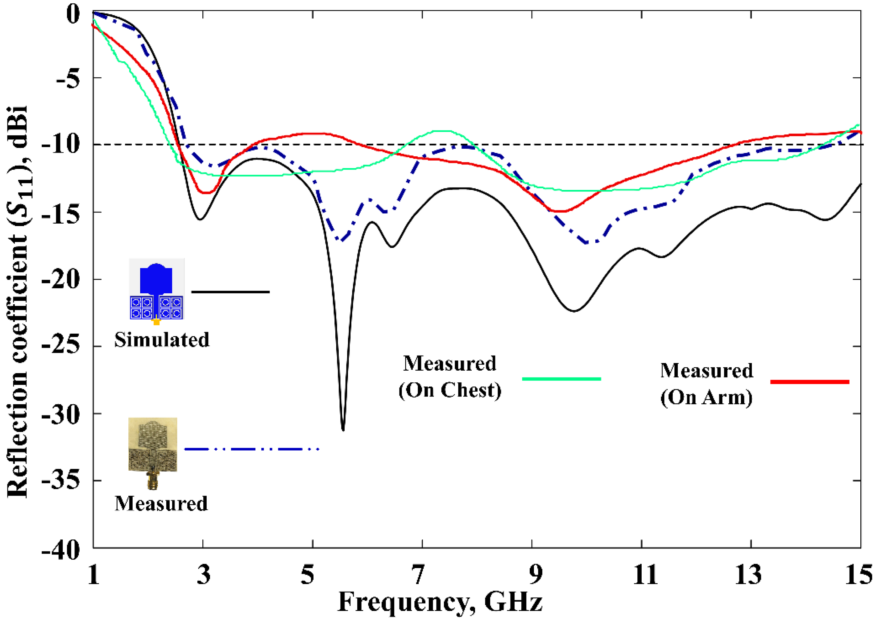
| Proposed work | 33 × 30 × 3 (0.825 λ0 × 0.75 λ0 × 0.075 λ0) | 2.55–15 BW= 12.45 | SNG/NZRI metamaterial | 142 | 4.84 | Compact size and wide operational bandwidth and FBW. |
| Para. | Value (mm) | Para. | Value (mm) | Para. | Value (mm) |
|---|---|---|---|---|---|
| Ls | 33.00 | c | 3.68 | x | 6.50 |
| Ws | 30.00 | d | 2.60 | y | 5.50 |
| Wp | 17.20 | e | 4.20 | r | 1.75 |
| Lp | 13.40 | f | 1.81 | g2 | 3.00 |
| Wg | 13.70 | g | 1.56 | g3 | 2.60 |
| Lg | 10.00 | g1 | 0.5 | Wf | 2.80 |
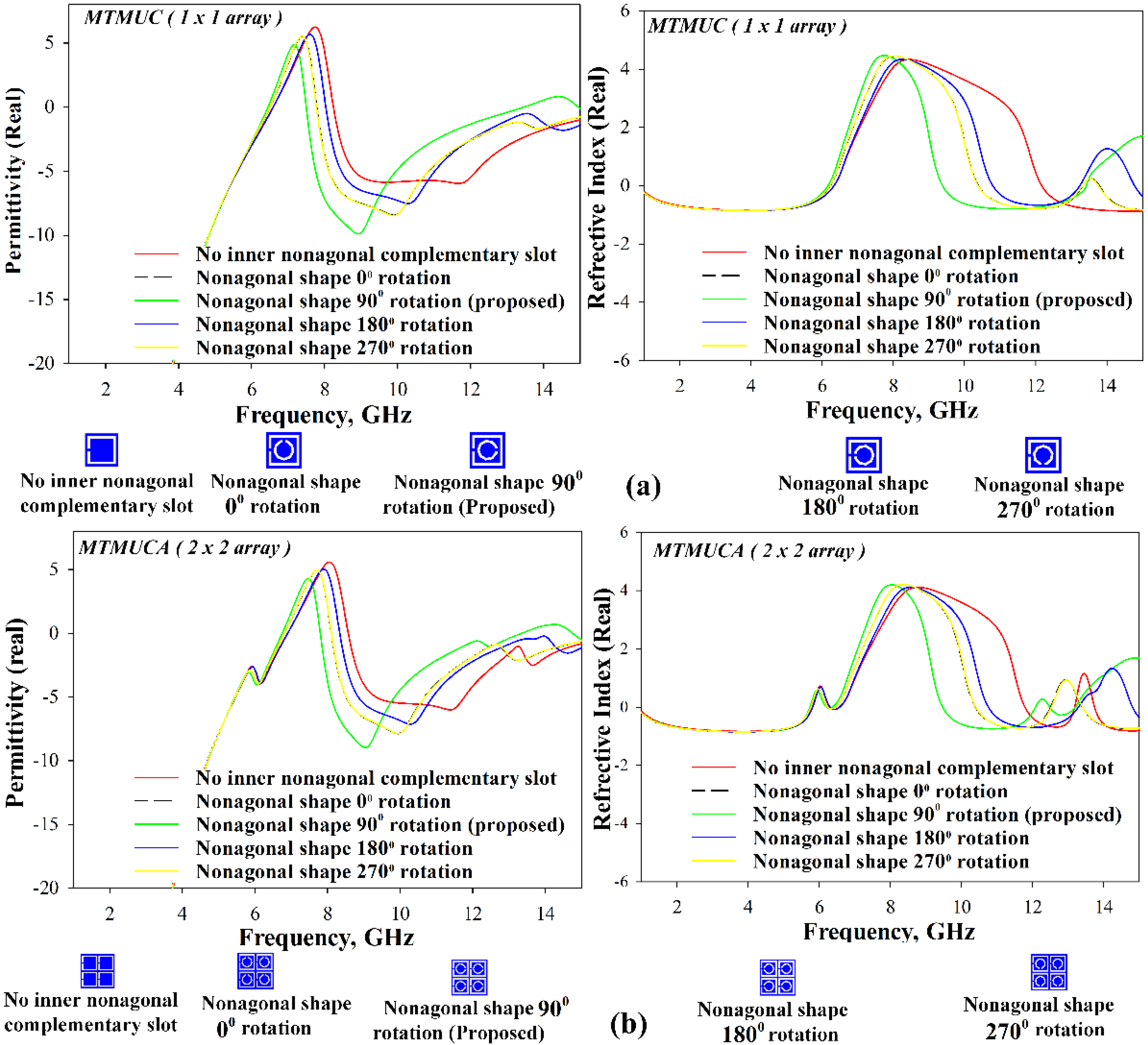
| MTM Structure | Negative Permittivity Band (GHz) | Negative Refractive Index Band (GHz) | ||
|---|---|---|---|---|
| Array Structure | Inner Nonagonal-Shaped Split Ring Rotation Angle (Degrees) | |||
| 1 × 1 (MTMUC) |      | – | 1–6.58 8.2–15 | 1–6.33 12.17–15 |
| 0 | 1–6.50 7.78–15 | 1–6.21 10.39–13.33 13.78–15 | ||
| 90 | 1–6.45 7.48–13.52 14.96–15 | 1–6.16 9.35–13.44 | ||
| 180 | 1–6.57 8.02–15 | 1–6.31 10.79–13.26 14.80–15.00 | ||
| 270 | 1–6.50 7.78–15 | 1–6.21 10.39–13.33 13.78–15 | ||
| 2 × 2 (MTMUCA) |      | – | 1–6.88 8.57–15 | 1–5.79 6.28–6.56 11.79–13.19 13.74–15 |
| 0 | 1–6.80 8.11–15 | 1–5.76 6.23–6.43 10.39–12.5 13.39–15 | ||
| 90 | 1–6.75 7.70–13.36 14.73–15 | 1–5.74 6.21–6.37 9.48–12.08 12.49–13.19 | ||
| 180 | 1–6.88 8.33–15 | 1–5.81 5.56–6.29 10.8–13.28 14.83–15 | ||
| 270 | 1–6.8 8.11–15 | 1–5.76 6.23–6.43 10.39–12.5 13.39–15 | ||
Publisher’s Note: MDPI stays neutral with regard to jurisdictional claims in published maps and institutional affiliations. |
© 2021 by the authors. Licensee MDPI, Basel, Switzerland. This article is an open access article distributed under the terms and conditions of the Creative Commons Attribution (CC BY) license (https://creativecommons.org/licenses/by/4.0/).
Share and Cite
Hossain, K.; Sabapathy, T.; Jusoh, M.; Abdelghany, M.A.; Soh, P.J.; Osman, M.N.; Yasin, M.N.M.; Rahim, H.A.; Al-Bawri, S.S. A Negative Index Nonagonal CSRR Metamaterial-Based Compact Flexible Planar Monopole Antenna for Ultrawideband Applications Using Viscose-Wool Felt. Polymers 2021, 13, 2819. https://doi.org/10.3390/polym13162819
Hossain K, Sabapathy T, Jusoh M, Abdelghany MA, Soh PJ, Osman MN, Yasin MNM, Rahim HA, Al-Bawri SS. A Negative Index Nonagonal CSRR Metamaterial-Based Compact Flexible Planar Monopole Antenna for Ultrawideband Applications Using Viscose-Wool Felt. Polymers. 2021; 13(16):2819. https://doi.org/10.3390/polym13162819
Chicago/Turabian StyleHossain, Kabir, Thennarasan Sabapathy, Muzammil Jusoh, Mahmoud A. Abdelghany, Ping Jack Soh, Mohamed Nasrun Osman, Mohd Najib Mohd Yasin, Hasliza A. Rahim, and Samir Salem Al-Bawri. 2021. "A Negative Index Nonagonal CSRR Metamaterial-Based Compact Flexible Planar Monopole Antenna for Ultrawideband Applications Using Viscose-Wool Felt" Polymers 13, no. 16: 2819. https://doi.org/10.3390/polym13162819
APA StyleHossain, K., Sabapathy, T., Jusoh, M., Abdelghany, M. A., Soh, P. J., Osman, M. N., Yasin, M. N. M., Rahim, H. A., & Al-Bawri, S. S. (2021). A Negative Index Nonagonal CSRR Metamaterial-Based Compact Flexible Planar Monopole Antenna for Ultrawideband Applications Using Viscose-Wool Felt. Polymers, 13(16), 2819. https://doi.org/10.3390/polym13162819