
Sulfonated Polysulfone/TiO2(B) Nanowires Composite Membranes as Polymer Electrolytes in Fuel Cells


 ,
,  and
and
Abstract
1. Introduction
2. Materials and Methods
2.1. Materials and Reagents
2.2. Preparation of TiO2(B) Nanowires
2.3. Polysulfone Sulfonation
2.4. Preparation of sPSU/TiO2(B) Membranes
2.5. Characterization and Measurements
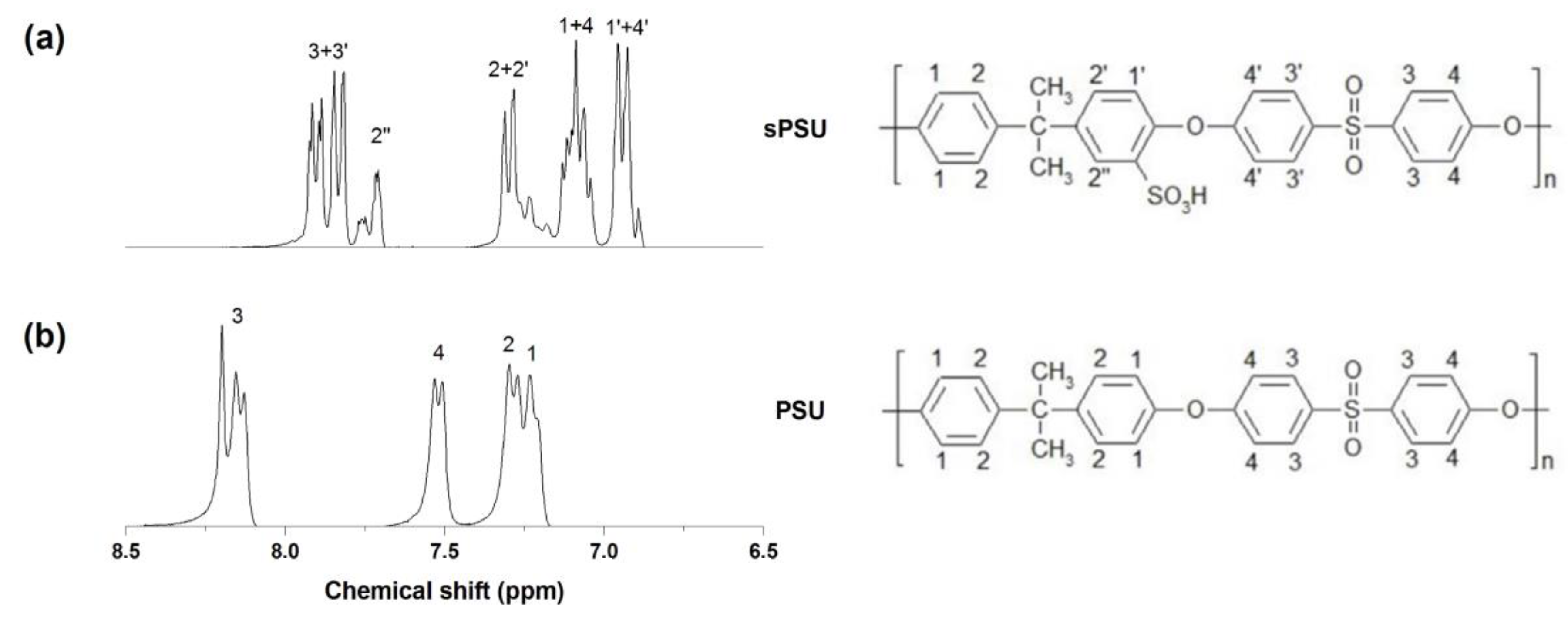
2.5.1. H-NMR Analysis
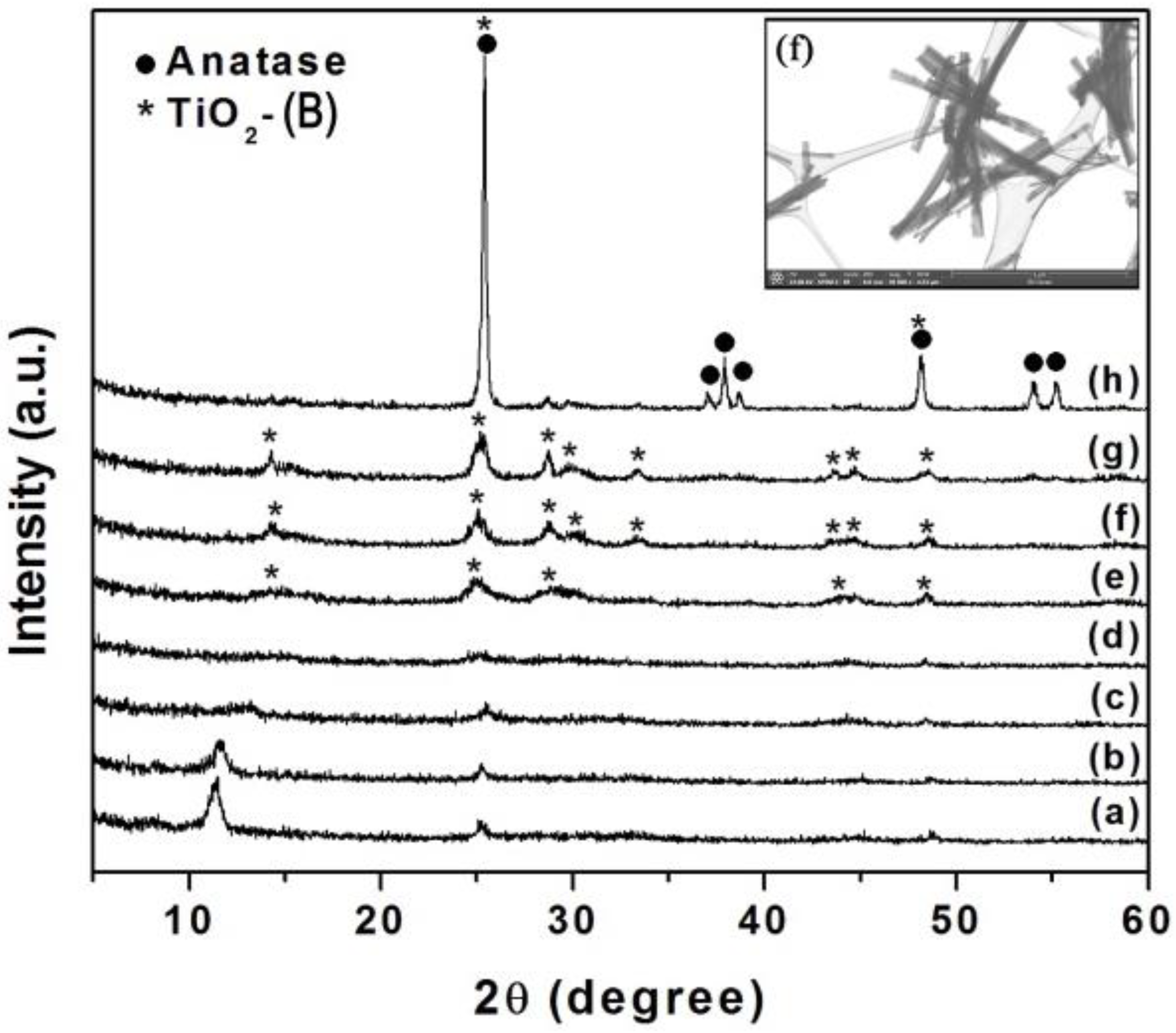
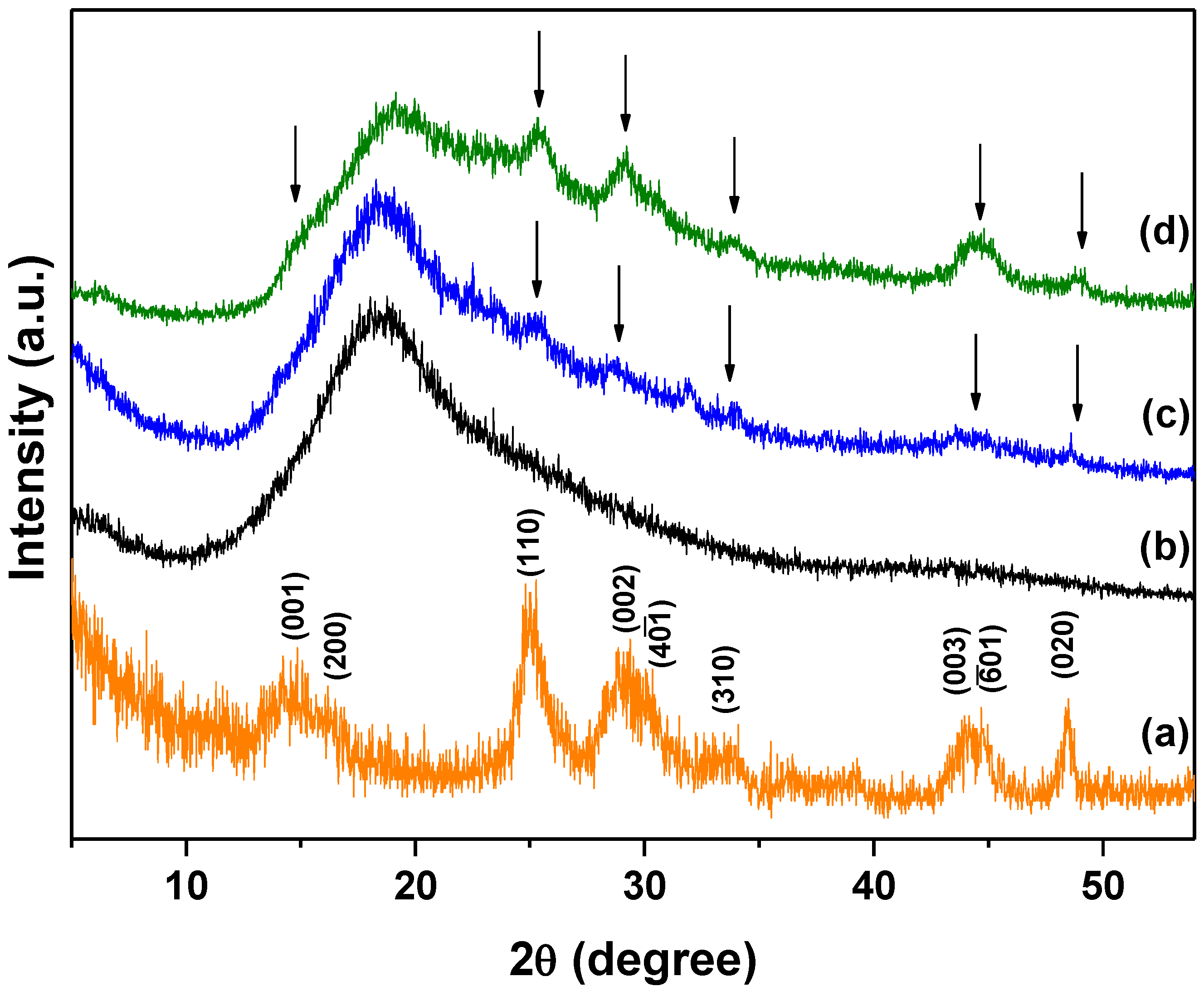
2.5.2. X-ray Diffraction (XRD)
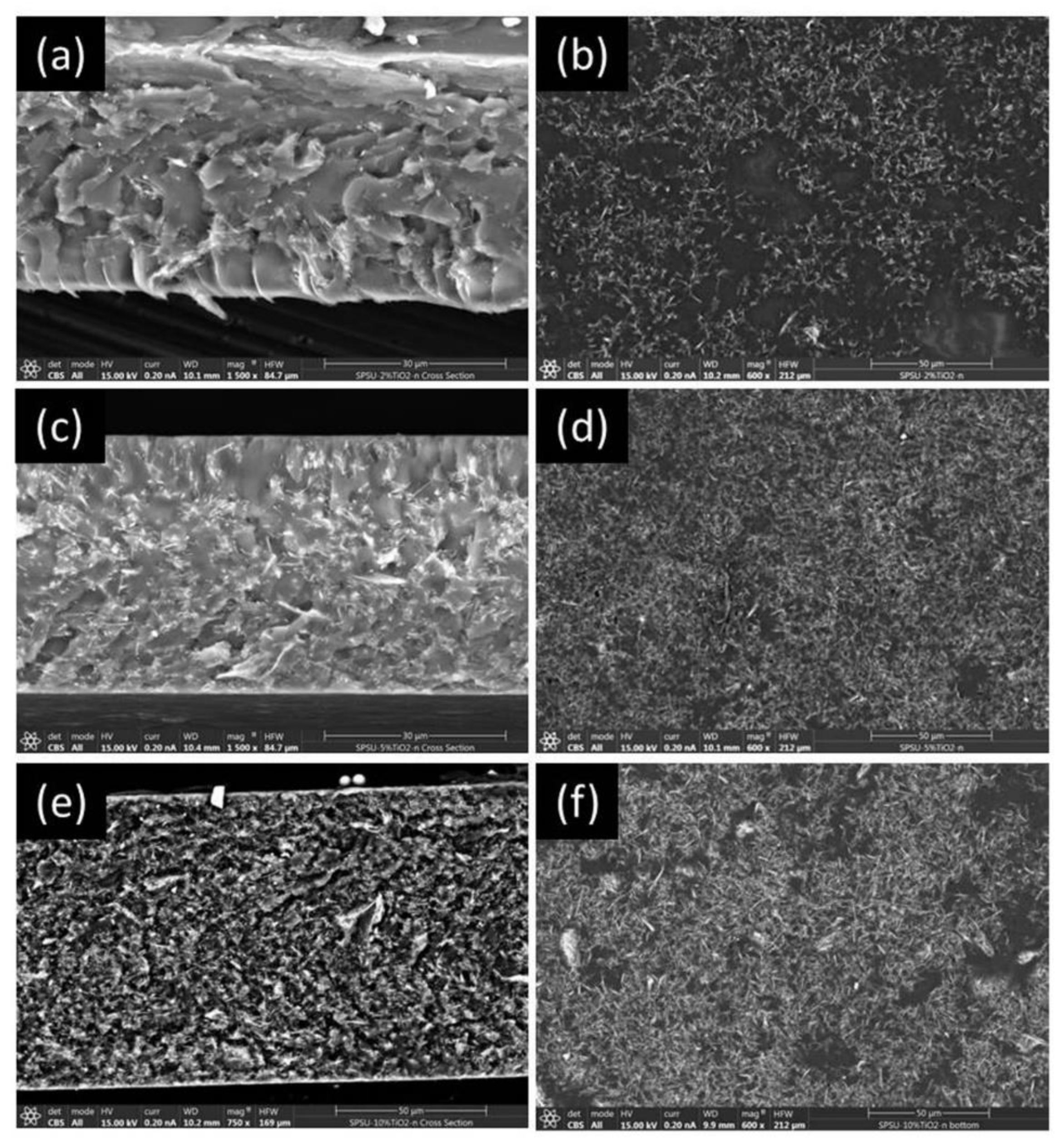
2.5.3. Scanning Electron Microscopy (SEM)
2.5.4. Water Absorption
2.5.5. Infrared Spectroscopy (FT-IR)
2.5.6. Thermogravimetric Analysis
2.5.7. Mechanical Properties
2.5.8. Impedance Spectroscopy
2.5.9. MEA Performances
3. Results
3.1. Sulfonation of PSU and Preparation of TiO2(B) Nanowires
3.2. X-ray Diffraction
3.3. Scanning Electron Microscopy
3.4. Water Uptake
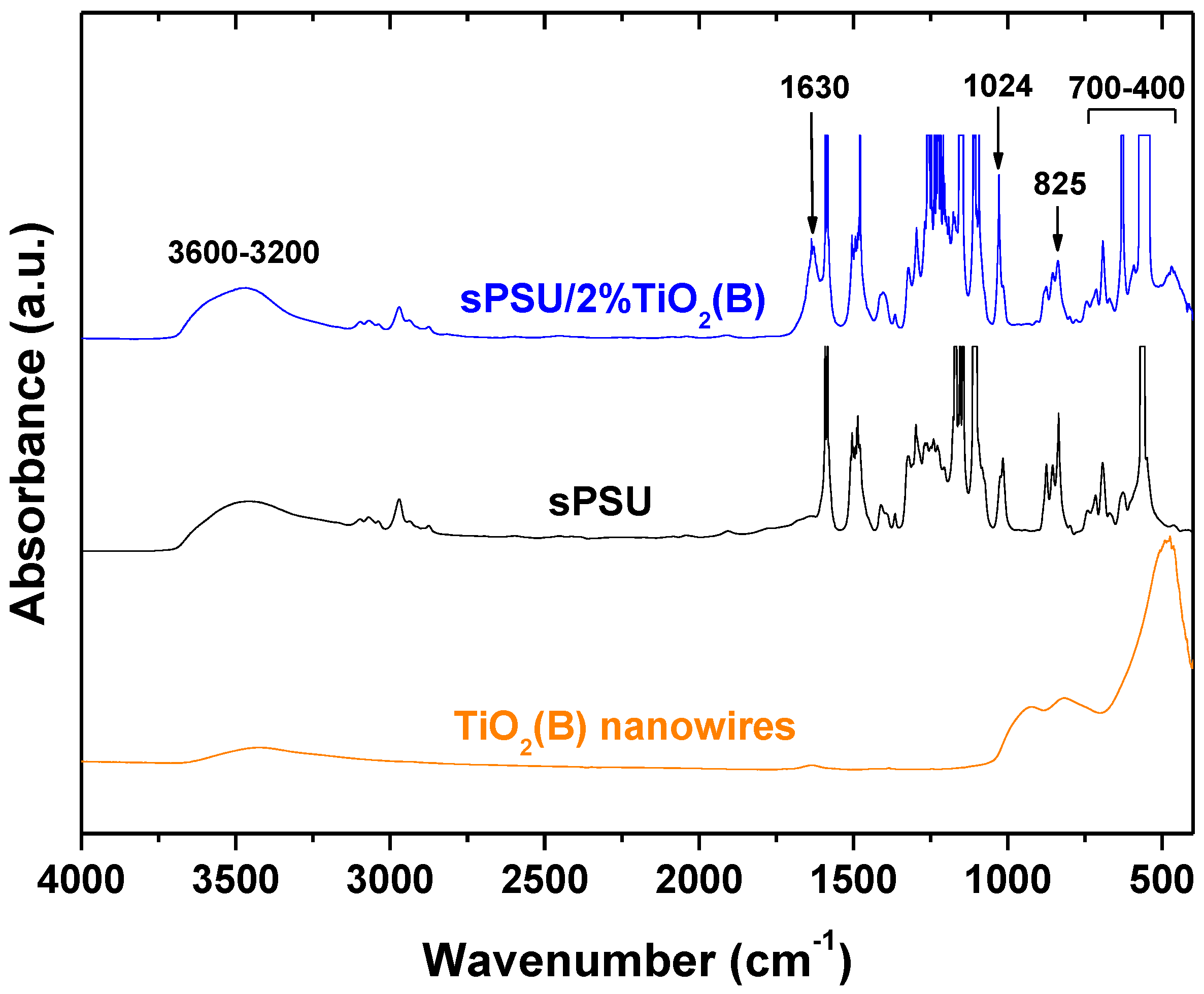
3.5. FTIR Analysis
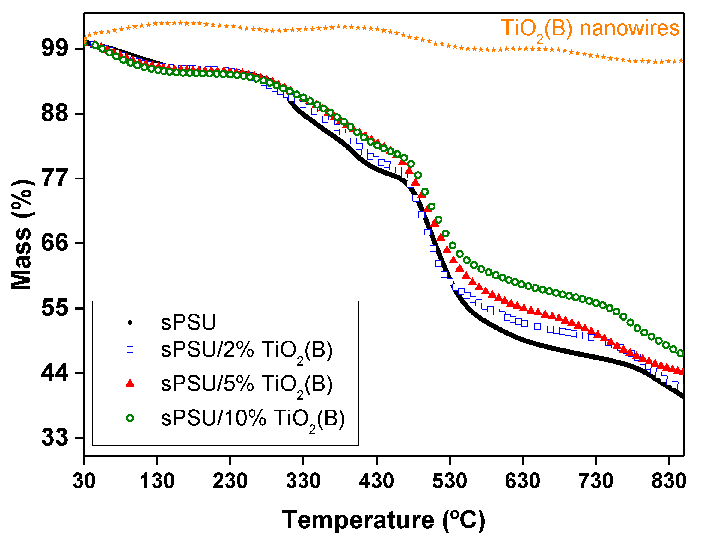
3.6. Thermal Analysis
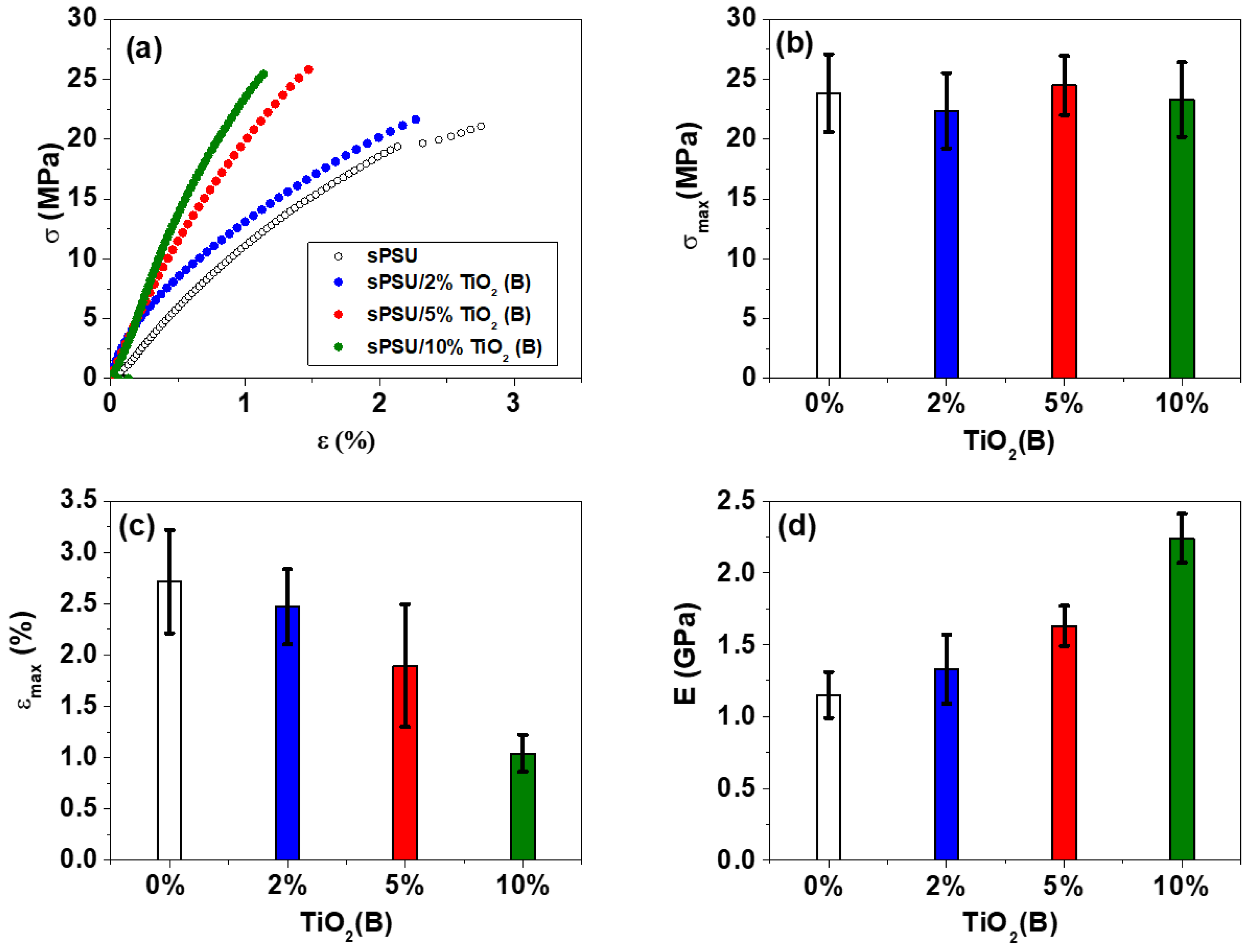
3.7. Mechanical Properties
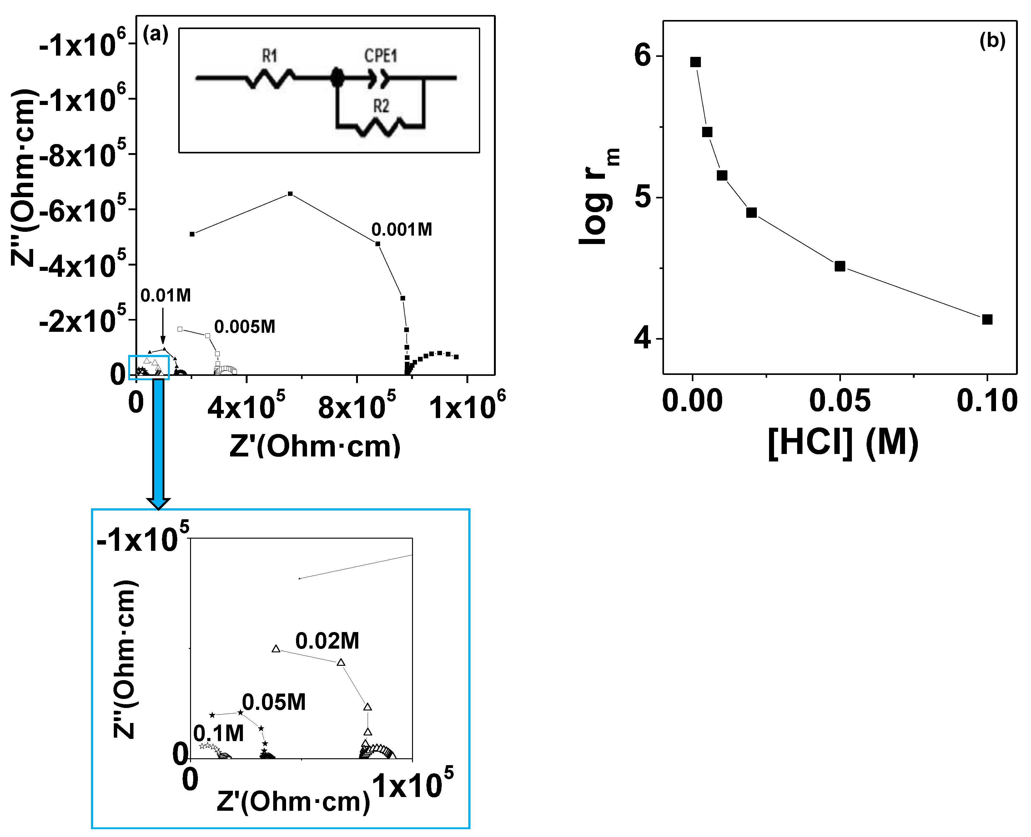
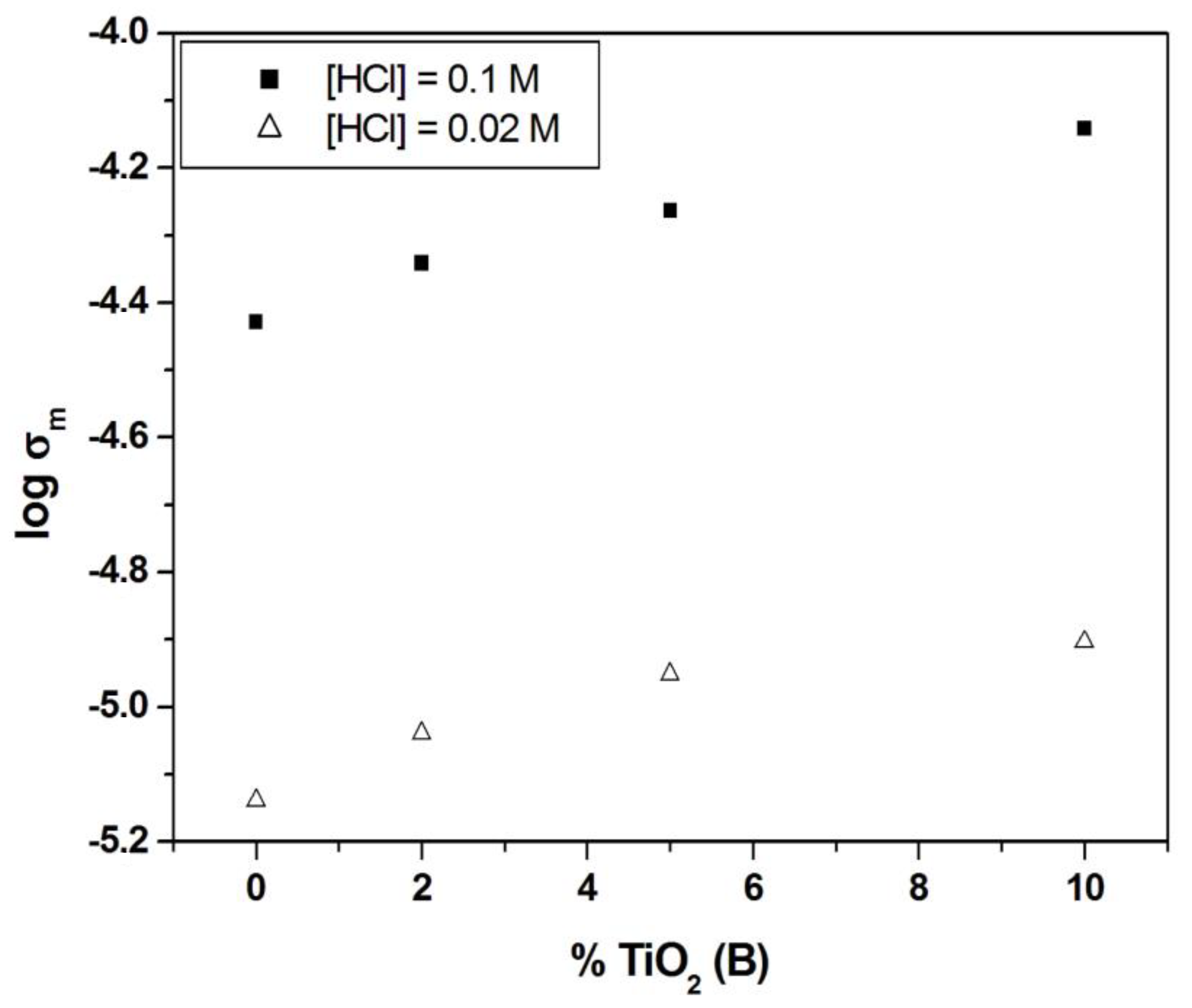
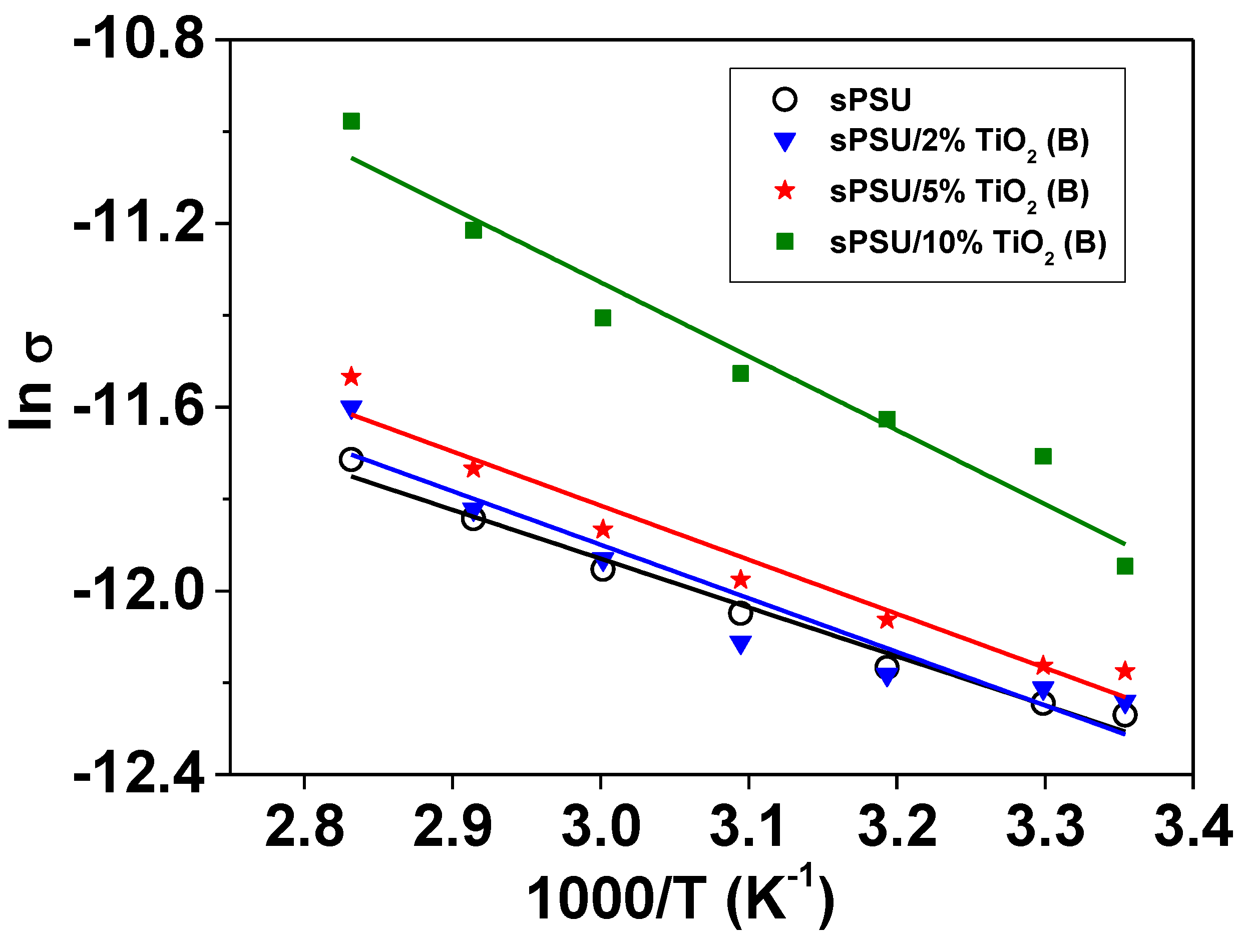
3.8. Ionic Conductivity
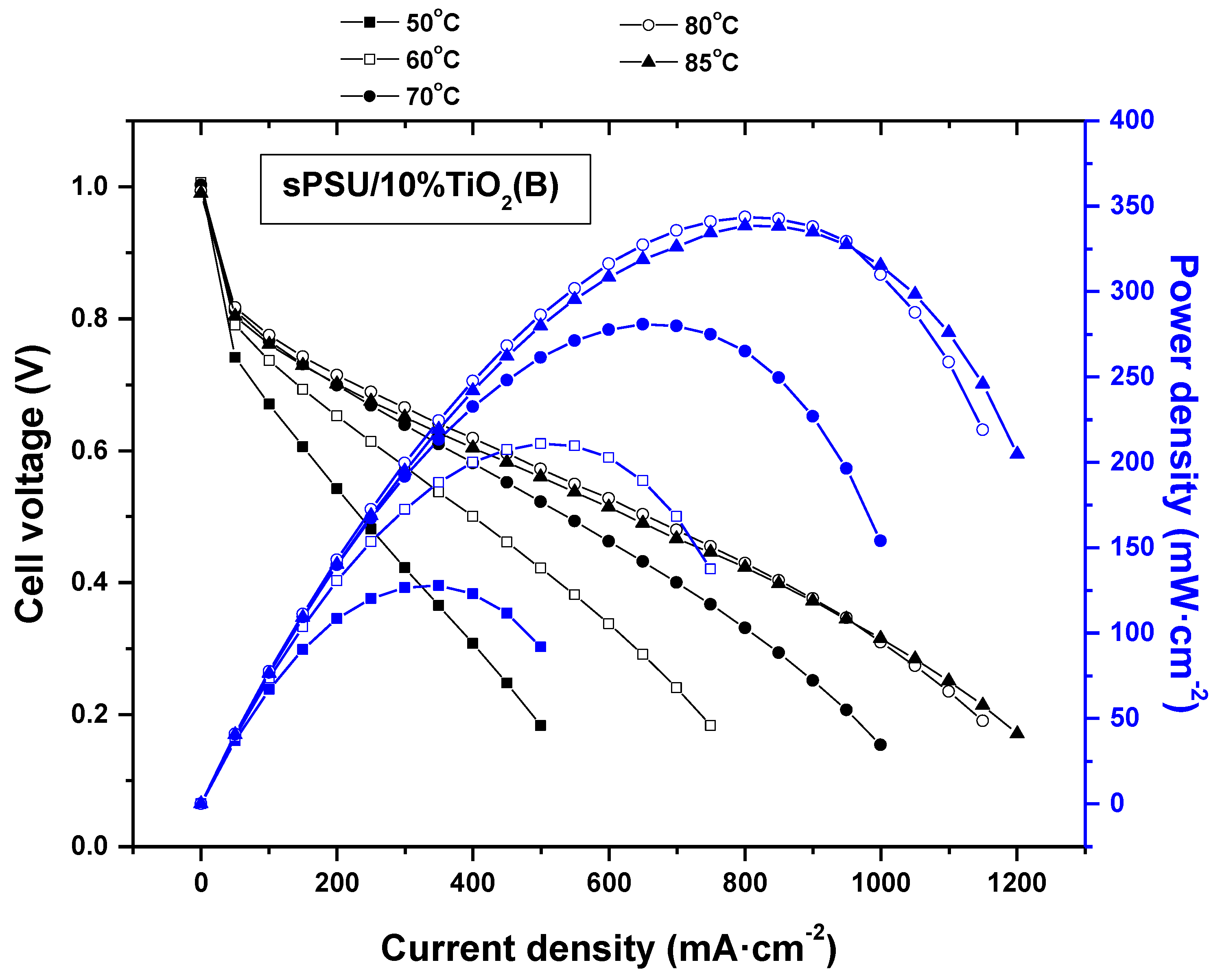
3.9. Fuel Cell Test
4. Conclusions
Supplementary Materials
Author Contributions
Funding
Institutional Review Board Statement
Informed Consent Statement
Data Availability Statement
Acknowledgments
Conflicts of Interest
References
- Hames, Y.; Kaya, K.; Baltacioglu, E.; Turksoy, A. Analysis of the control strategies for fuel saving in the hydrogen fuel cell vehicles. Int. J. Hydrogen Energy 2018, 43, 10810–10821. [Google Scholar] [CrossRef]
- Peighambardoust, S.J.; Rowshanzamir, S.; Amjadi, M. Review of the Proton Exchange Membranes for fuel Cell Applications; Elsevier: Amsterdam, The Netherlands, 2010; Volume 35, ISBN 2177491223. [Google Scholar]
- Pan, M.; Pan, C.; Li, C.; Zhao, J. A review of membranes in proton exchange membrane fuel cells: Transport phenomena, performance and durability. Renew. Sustain. Energy Rev. 2021, 141, 110771. [Google Scholar] [CrossRef]
- Barbir, F.; Gómez, T. Efficiency and economics of proton exchange membrane (PEM) fuel cells. Int. J. Hydrogen Energy 1997, 22, 1027–1037. [Google Scholar] [CrossRef]
- Fiori, C.; Dell’Era, A.; Zuccari, F.; Santiangeli, A.; D’Orazio, A.; Orecchini, F. Critical review of fuel cell’s membranes and identification of alternative types for automotive applications. Int. J. Hydrogen Energy 2015, 40, 11949–11959. [Google Scholar] [CrossRef]
- Kiran, V.; Gaur, B. Sulfonated poly (arylene ether sulfone) proton exchange membranes for fuel cell applications. Green Process. Synth. 2015, 4, 283–297. [Google Scholar] [CrossRef]
- Xing, P.; Robertson, G.P.; Guiver, M.D.; Mikhailenko, S.D.; Wang, K.; Kaliaguine, S. Synthesis and characterization of sulfonated poly(ether ether ketone) for proton exchange membranes. J. Membr. Sci. 2004, 229, 95–106. [Google Scholar] [CrossRef]
- Schuster, M.; Kreuer, K.-D.; Andersen, H.T.; Maier, J. Sulfonated Poly(phenylene sulfone) Polymers as Hydrolytically and Thermooxidatively Stable Proton Conducting Ionomers. Macromolecules 2007, 40, 598–607. [Google Scholar] [CrossRef]
- Chen, J.-C.; Wu, J.-A.; Lee, C.-Y.; Tsai, M.-C.; Chen, K.-H. Novel polyimides containing benzimidazole for temperature proton exchange membrane fuel. J. Membr. Sci. 2015, 483, 144–154. [Google Scholar] [CrossRef]
- Guo, Q.; Pintauro, P.N.; Tang, H.; O’Connor, S. Sulfonated and crosslinked polyphosphazene-based proton-exchange membranes. J. Membr. Sci. 1999, 154, 175–181. [Google Scholar] [CrossRef]
- Wang, G.; Yao, Y.; Xiao, G.; Yan, D. Novel sulfonated polybenzothiazoles with outstanding dimensional stability for proton exchange membranes. J. Membr. Sci. 2013, 425–426, 200–207. [Google Scholar] [CrossRef]
- Lufrano, F.; Squadrito, G.; Patti, A.; Passalacqua, E. Sulfonated polysulfone as promising membranes for polymer electrolyte fuel cells. J. Appl. Polym. Sci. 2000, 77, 1250–1256. [Google Scholar] [CrossRef]
- Lafitte, B.; Karlsson, L.E.; Jannasch, P. Sulfophenylation of Polysulfones for Proton-Conducting Fuel Cell Membranes. Macromol. Rapid Commun. 2002, 23, 896–900. [Google Scholar] [CrossRef]
- Martos, A.M.; Sanchez, J.Y.; Várez, A.; Levenfeld, B. Electrochemical and structural characterization of sulfonated polysulfone. Polym. Test. 2015, 45, 185–193. [Google Scholar] [CrossRef]
- Simari, C.; Prejanò, M.; Lufrano, E.; Sicilia, E.; Nicotera, I. Exploring the structure-performance relationship of sulfonated polysulfone proton exchange membrane by a combined computational and experimental approach. Polymers 2021, 13, 959. [Google Scholar] [CrossRef]
- Martínez-Morlanes, M.J.; Martos, A.M.; Várez, A.; Levenfeld, B. Synthesis and characterization of novel hybrid polysulfone/silica membranes doped with phosphomolybdic acid for fuel cell applications. J. Membr. Sci. 2015, 492, 371–379. [Google Scholar] [CrossRef]
- Padmavathi, R.; Karthikumar, R.; Sangeetha, D. Multilayered sulphonated polysulfone/silica composite membranes for fuel cell applications. Electrochim. Acta 2012, 71, 283–293. [Google Scholar] [CrossRef]
- Bisht, S.; Balaguru, S.; Ramachandran, S.K.; Gangasalam, A.; Kweon, J. Proton exchange composite membranes comprising SiO2, sulfonated SiO2, and metal–organic frameworks loaded in SPEEK polymer for fuel cell applications. J. Appl. Polym. Sci. 2021, 138, 1–15. [Google Scholar] [CrossRef]
- Rosdi, A.N.; Kang, Y.L.; Purushothaman, M.; Ibrahim, S.; Pichiah, S. Preparation and characterization of zeolite polymer composite proton exchange membrane. Desalin. Water Treat. 2015, 1–9. [Google Scholar] [CrossRef]
- Ozden, A.; Ercelik, M.; Devrim, Y.; Colpan, C.O.; Hamdullahpur, F. Hamdullahpur, Evaluation of sulfonated polysulfone/zirconium hydrogen phosphate composite membranes for direct methanol fuel cells. Electrochim. Acta 2017, 256, 196–210. [Google Scholar] [CrossRef]
- Devrim, Y.; Erkan, S.; Baç, N.; Eroğlu, I. Preparation and characterization of sulfonated polysulfone/titanium dioxide composite membranes for proton exchange membrane fuel cells. Int. J. Hydrogen Energy 2009, 34, 3467–3475. [Google Scholar] [CrossRef]
- Unnikrishnan, L.; Mohanty, S.; Nayak, S.K.; Jayan, N.P. Sulfonated polysulfone/TiO2 nanocomposite membranes for fuel cell application. Int. J. Plast. Technol. 2011, 15, 1–20. [Google Scholar] [CrossRef]
- Ali, N.; Said, A.; Ali, F.; Khan, M.; Sheikh, Z.A.; Bilal, M. Development and Characterization of Functionalized Titanium Dioxide-Reinforced Sulfonated Copolyimide (SPI/TiO2) Nanocomposite Membranes with Improved Mechanical, Thermal, and Electrochemical Properties. J. Inorg. Organomet. Polym. Mater. 2020, 30, 4585–4596. [Google Scholar] [CrossRef]
- Shanmugam, S.; Ketpang, K.; Aziz, M.A.; Oh, K.; Lee, K.; Son, B.; Chanunpanich, N. Composite polymer electrolyte membrane decorated with porous titanium oxide nanotubes for fuel cell operating under low relative humidity. Electrochim. Acta 2021, 384, 138407. [Google Scholar] [CrossRef]
- Ruiz Gómez, E.E.; Mina Hernández, J.H.; Diosa Astaiza, J.E. Development of a Chitosan/PVA/TiO2 nanocomposite for application as a solid polymeric electrolyte in fuel cells. Polymers 2020, 12, 1691. [Google Scholar] [CrossRef]
- Mattioli, G.; Filippone, F.; Caminiti, R.; Bonapasta, A.A. Short Hydrogen Bonds at the Water/TiO2 (Anatase) Interface. J. Phys. 2008, 2, 13579–13586. [Google Scholar] [CrossRef]
- Sacca, A.; Carbone, A.; Passalacqua, E.; D’epifanio, A.; Licoccia, S.; Traversa, E.; Sala, E.; Traini, F.; Ornelas, R. Nafion–TiO2 hybrid membranes for medium temperature polymer electrolyte fuel cells (PEFCs). J. Power Sources 2005, 152, 16–21. [Google Scholar] [CrossRef]
- Othman, M.A.; Amat, N.F.; Ahmad, B.H.; Rajan, J. Electrical Conductivity Characteristic of TiO2 Nanowires From Hydrothermal Method. J. Phys. Conf. Ser. 2014, 495, 012027. [Google Scholar] [CrossRef]
- Li, J.; Wan, W.; Zhou, H.; Li, J.; Xu, D. Hydrothermal synthesis of TiO2(B) nanowires with ultrahigh surface area and their fast charging and discharging properties in Li-ion batteries. Chem. Commun. 2011, 47, 3439–3441. [Google Scholar] [CrossRef] [PubMed]
- Marchand, R.; Brohan, L.; Tournoux, M. TiO2(B) a new form of titanium dioxide and the potassium octatitanate K2Ti8O17. Mater. Res. Bull. 1980, 15, 1129–1133. [Google Scholar] [CrossRef]
- Liu, Z.; Andreev, Y.G.; Armstrong, A.R.; Brutti, S.; Ren, Y.; Bruce, P.G. TiO2(B): The effect of size and shape on anode properties for Li-ion batteries. Prog. Nat. Sci. Mater. Int. 2013, 23, 235–244. [Google Scholar] [CrossRef]
- Yoshida, R.; Suzuki, Y.; Yoshikawa, S. Syntheses of TiO2(B) nanowires and TiO2 anatase nanowires by hydrothermal and post-heat treatments. J. Solid State Chem. 2005, 178, 2179–2185. [Google Scholar] [CrossRef]
- Chao, H.S.; Kelsey, D.R. Process for Preparing Sulfonated Poly(Arylether)Resins. U.S. Patent 4,625,000A, 25 November 1986. [Google Scholar]
- Noshay, A.; Robeson, L.M. Sulfonated polysulfone. J. Appl. Polym. Sci. 1976, 20, 1885–1903. [Google Scholar] [CrossRef]
- Benavente, J.; Canas, A.; Ariza, M.J.; Lozano, A.E.; De Abajo, J. Electrochemical parameters of sulfonated poly(ether ether sulfone) membranes in HCl solutions determined by impedance spectroscopy and membrane potential measurements. Solid State Ion. 2001, 145, 53–60. [Google Scholar] [CrossRef]
- Iojoiu, C.; Genova-Dimitrova, P.; Maréchal, M.; Sanchez, J.-Y. Chemical and physicochemical characterizations of ionomers. Electrochim. Acta 2006, 51, 4789–4801. [Google Scholar] [CrossRef]
- Chen, Q.; Du, G.H.; Zhang, S.; Peng, L.M. The structure of trititanate nanotubes. Acta Crystallogr. Sect. B Struct. Sci. 2002, 58, 587–593. [Google Scholar] [CrossRef]
- Suzuki, Y.; Yoshikawa, S. Synthesis and Thermal Analyses of TiO2-Derived Nanotubes Prepared by the Hydrothermal Method. J. Mater. Res. 2011, 19, 982–985. [Google Scholar] [CrossRef]
- Armstrong, A.R.; Armstrong, G.; Canales, J.; Bruce, P.G. TiO2–B nanowires as negative electrodes for rechargeable lithium batteries. J. Power Sources 2005, 146, 501–506. [Google Scholar] [CrossRef]
- Smitha, B.; Sridhar, S.; Khan, A.A. Proton conducting composite membranes from polysulfone and heteropolyacid for fuel cell applications. J. Polym. Sci. Part. B Polym. Phys. 2005, 43, 1538–1547. [Google Scholar] [CrossRef]
- Finnie, K.S.; Cassidy, D.J.; Bartlett, J.R.; Woolfrey, J.L. IR spectroscopy of surface water and hydroxyl species on nanocrystalline TiO2 films. Langmuir 2001, 17, 816–820. [Google Scholar] [CrossRef]
- Vuk, A.Š.; Ješe, R.; Orel, B.; Dražič, G. The effect of surface hydroxyl groups on the adsorption properties of nanocrystalline TiO2 films. Int. J. Photoenergy 2005, 7, 163–168. [Google Scholar] [CrossRef]
- Slade, S.M.; Smith, J.R.; Campbell, S.A.; Ralph, T.R.; Ponce De León, C.; Walsh, F.C. Characterisation of a re-cast composite Nafion® 1100 series of proton exchange membranes incorporating inert inorganic oxide particles. Electrochim. Acta 2010, 55, 6818–6829. [Google Scholar] [CrossRef]
- Şahİn, A.; İrfan, A. Synthesis and Characterization of Polyvinyl Alcohol Based and Titaniumdioxide Doped Nanocomposite Membrane. Isi Bilimi ve Teknigi Dergisi 2014, 34, 153–162. [Google Scholar]
- Beranek, R.; Kisch, H. Tuning the optical and photoelectrochemical properties of surface-modified TiO2. Photochem. Photobiol. Sci. 2008, 7, 40–48. [Google Scholar] [CrossRef] [PubMed]
- Wei, Y.; Chu, H.-Q.; Dong, B.-Z.; Li, X.; Xia, S.-J.; Qiang, Z.-M. Effect of TiO2 nanowire addition on PVDF ultrafiltration membrane performance. Desalination 2011, 272, 90–97. [Google Scholar] [CrossRef]
- Perumal, S.; Sambandam, C.G.; Prabu, M.K.; Ananthakumar, S. Synthesis and characterization studies of nano TiO2 prepared via sol-gel method. Int. J. Res. Eng. Technol. 2014, 03, 651–657. [Google Scholar] [CrossRef]
- Shao, Z.-G.; Joghee, P.; Hsing, I.-M. Preparation and characterization of hybrid Nafion–silica membrane doped with phosphotungstic acid for high temperature operation of proton exchange membrane fuel cells. J. Membr. Sci. 2004, 229, 43–51. [Google Scholar] [CrossRef]
- Wang, D.; Chen, A. Trace Explosive sensor based on Titanium Oxide- B Nanowires. In Graphene, Carbon Nanotubes, and Nanostructures. Techniques and Applications; CRC Press Taylor & Francis Group: Boca Raton, FL, USA, 2013; p. 289. ISBN 978-1-4665-6057. [Google Scholar]
- Wu, R.-J.; Sun, Y.-L.; Lin, C.-C.; Chen, H.-W.; Chavali, M. Composite of TiO2 nanowires and Nafion as humidity sensor material. Sens. Actuators B Chem. 2006, 115, 198–204. [Google Scholar] [CrossRef]
- Wang, G.; Wang, Q.; Lu, W.; Li, J. Photoelectrochemical Study on Charge Transfer Properties of TiO2—B Nanowires with an Application as Humidity Sensors. J. Phys. Chem. B 2006, 110, 22029–22034. [Google Scholar] [CrossRef] [PubMed]
- Zhang, J.; Fei, G.; Liang, Y.; Zhang, Y.; Zhao, J. Influence of silica content in sulfonated polysulfone/ phosphotungstic acid hybrid membranes on properties for fuel cell application. E Polym. 2010, 1–10. [Google Scholar] [CrossRef]
- Shao, Z.; Xu, H.; Li, M.; Hsing, I. Hybrid Nafion—inorganic oxides membrane doped with heteropolyacids for high temperature operation of proton exchange membrane fuel cell. Solid State Ion. 2006, 177, 779–785. [Google Scholar] [CrossRef]
- Shao, P.L.; Mauritz, K.A.; Moore, R.B. Perfluorosulfonate ionomer/SiO2-TiO2 nanocomposites via polymer-in situ sol-gel chemistry: Sequential alkoxide procedure. J. Polym. Sci. Part. B Polym. Phys. 1996, 34, 873–882. [Google Scholar] [CrossRef]
- Li, Y.; Nguyen, Q.T.; Schaetzel, P.; Lixon-Buquet, C.; Colasse, L.; Ratieuville, V.; Marais, S. Proton exchange membranes from sulfonated polyetheretherketone and sulfonated polyethersulfone-cardo blends: Conductivity, water sorption and permeation properties. Electrochim. Acta 2013, 111, 419–433. [Google Scholar] [CrossRef]
- Ureña, N.; Pérez-Prior, M.T.; Río, C.; Várez, A.; Sanchez, Y.; Iojoiu, C.; Levenfeld, B. Multiblock Copolymers of Sulfonated PSU/PPSU Poly(ether sulfone)s as solid electrolytes for Proton Exchange Membrane Fuel Cells. Electrochim. Acta 2019, 301, 1–13. [Google Scholar] [CrossRef]
- Zhengbang, W.; Tang, H.; Mu, P. Self-assembly of durable Nafion/TiO2 nanowire electrolyte membranes for elevated-temperature PEM fuel cells. J. Membr. Sci. 2011, 369, 250–257. [Google Scholar] [CrossRef]


| Membrane | Water Uptake (%) |
|---|---|
| sPSU | 29 ± 3 |
| sPSU/1%TiO2(B) | 45 ± 3 |
| sPSU/2%TiO2(B) | 49 ± 3 |
| sPSU/5%TiO2(B) | 49 ± 4 |
| sPSU/10%TiO2(B) | 41 ± 5 |
Publisher’s Note: MDPI stays neutral with regard to jurisdictional claims in published maps and institutional affiliations. |
© 2021 by the authors. Licensee MDPI, Basel, Switzerland. This article is an open access article distributed under the terms and conditions of the Creative Commons Attribution (CC BY) license (https://creativecommons.org/licenses/by/4.0/).
Share and Cite
Martinez-Morlanes, M.J.; de la Torre-Gamarra, C.; Pérez-Prior, M.T.; Lara-Benito, S.; del Rio, C.; Várez, A.; Levenfeld, B. Sulfonated Polysulfone/TiO2(B) Nanowires Composite Membranes as Polymer Electrolytes in Fuel Cells. Polymers 2021, 13, 2030. https://doi.org/10.3390/polym13122030
Martinez-Morlanes MJ, de la Torre-Gamarra C, Pérez-Prior MT, Lara-Benito S, del Rio C, Várez A, Levenfeld B. Sulfonated Polysulfone/TiO2(B) Nanowires Composite Membranes as Polymer Electrolytes in Fuel Cells. Polymers. 2021; 13(12):2030. https://doi.org/10.3390/polym13122030
Chicago/Turabian StyleMartinez-Morlanes, Maria Jose, Carmen de la Torre-Gamarra, María Teresa Pérez-Prior, Sara Lara-Benito, Carmen del Rio, Alejandro Várez, and Belen Levenfeld. 2021. "Sulfonated Polysulfone/TiO2(B) Nanowires Composite Membranes as Polymer Electrolytes in Fuel Cells" Polymers 13, no. 12: 2030. https://doi.org/10.3390/polym13122030
APA StyleMartinez-Morlanes, M. J., de la Torre-Gamarra, C., Pérez-Prior, M. T., Lara-Benito, S., del Rio, C., Várez, A., & Levenfeld, B. (2021). Sulfonated Polysulfone/TiO2(B) Nanowires Composite Membranes as Polymer Electrolytes in Fuel Cells. Polymers, 13(12), 2030. https://doi.org/10.3390/polym13122030