
Amorphous Carbon Coatings for Total Knee Replacements—Part I: Deposition, Cytocompatibility, Chemical and Mechanical Properties

 ,
, 
 ,
,  , , ,
, , , 
Abstract
1. Introduction
2. Materials and Methods
2.1. Materials
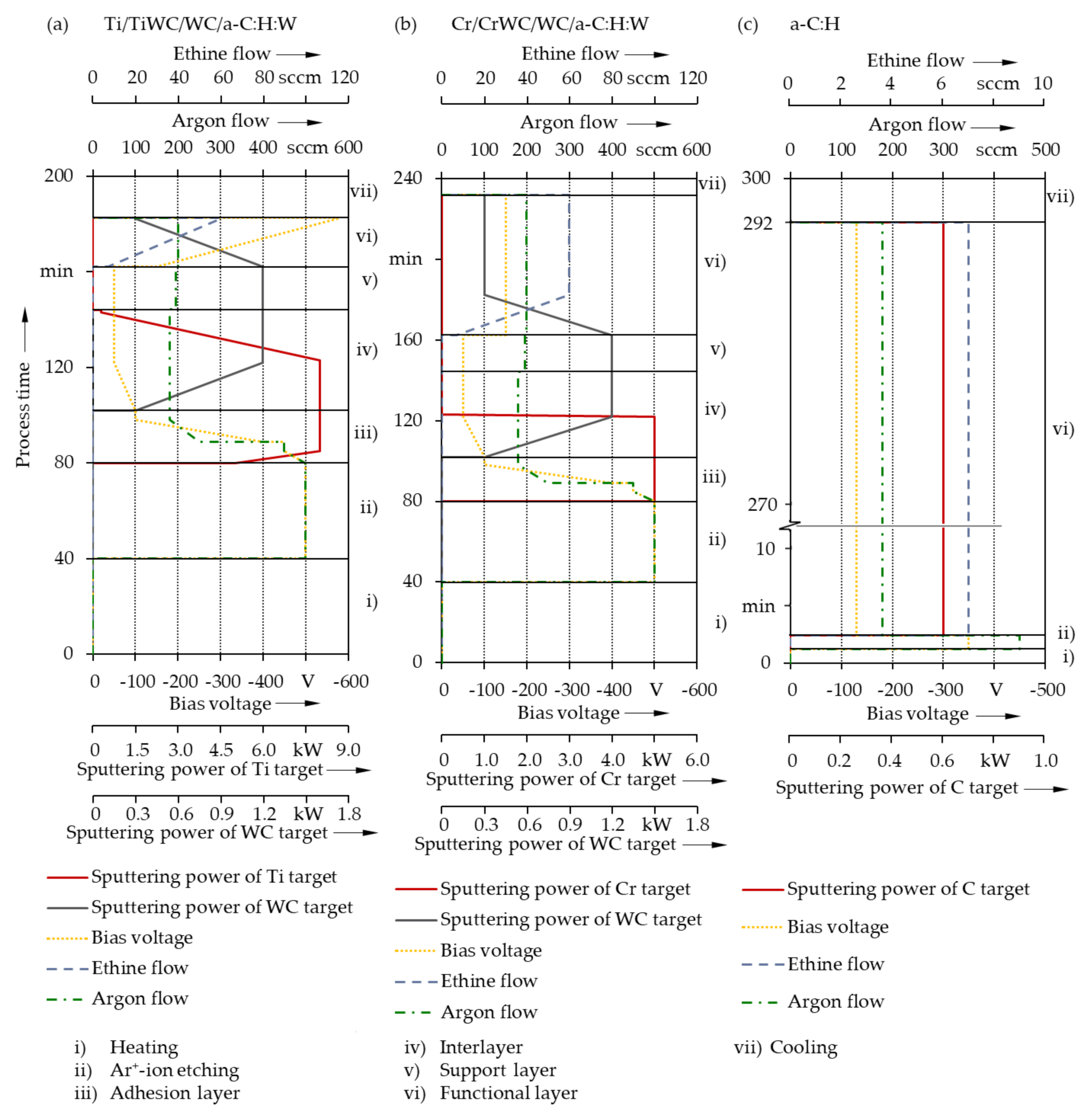
2.2. Coating Deposition
2.3. Morphology and Structure Characterization
2.4. Chemical and Cytological Characterization
2.5. Mechanical Characterization
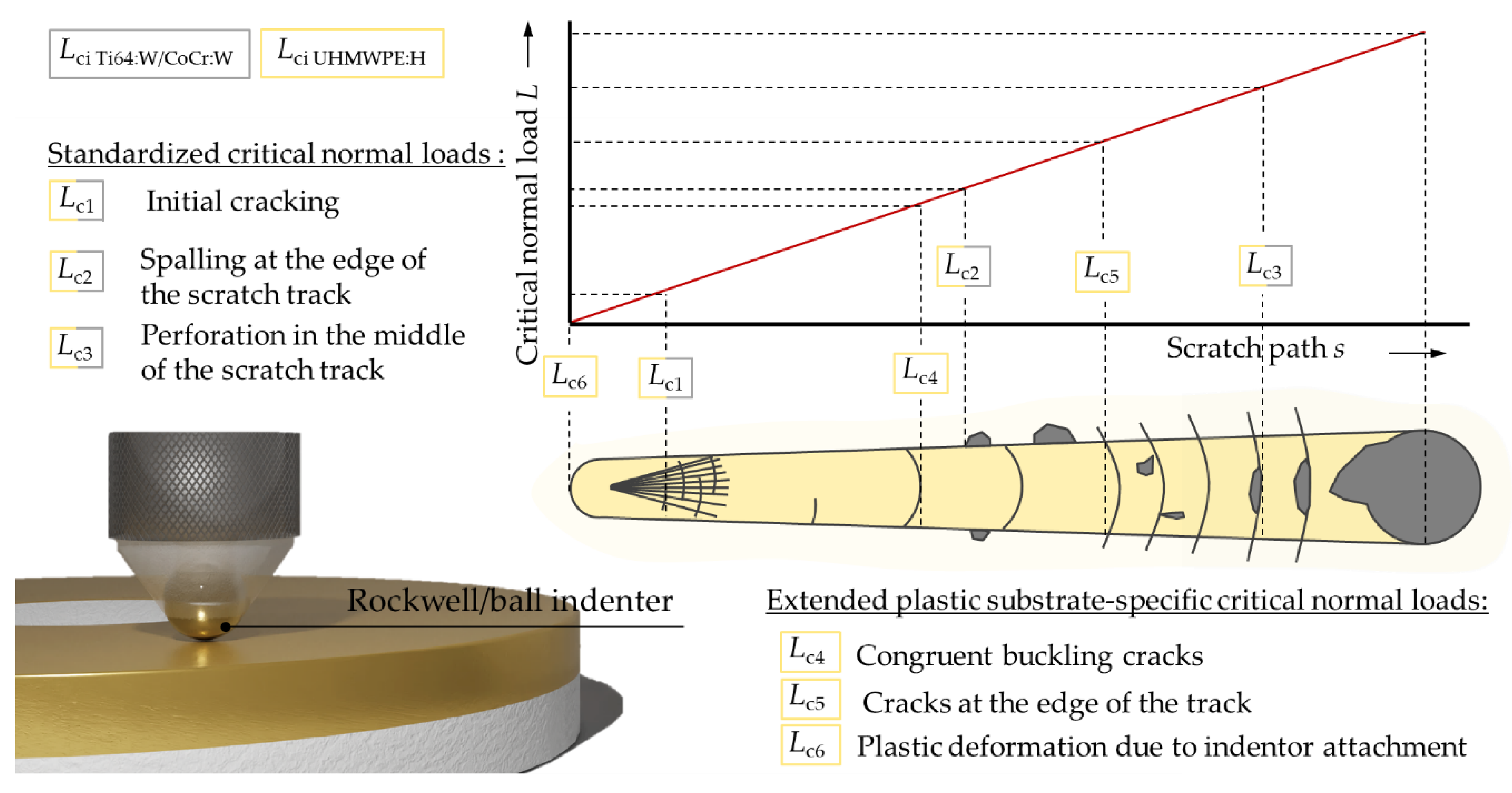
2.6. Adhesion
3. Results and Discussion
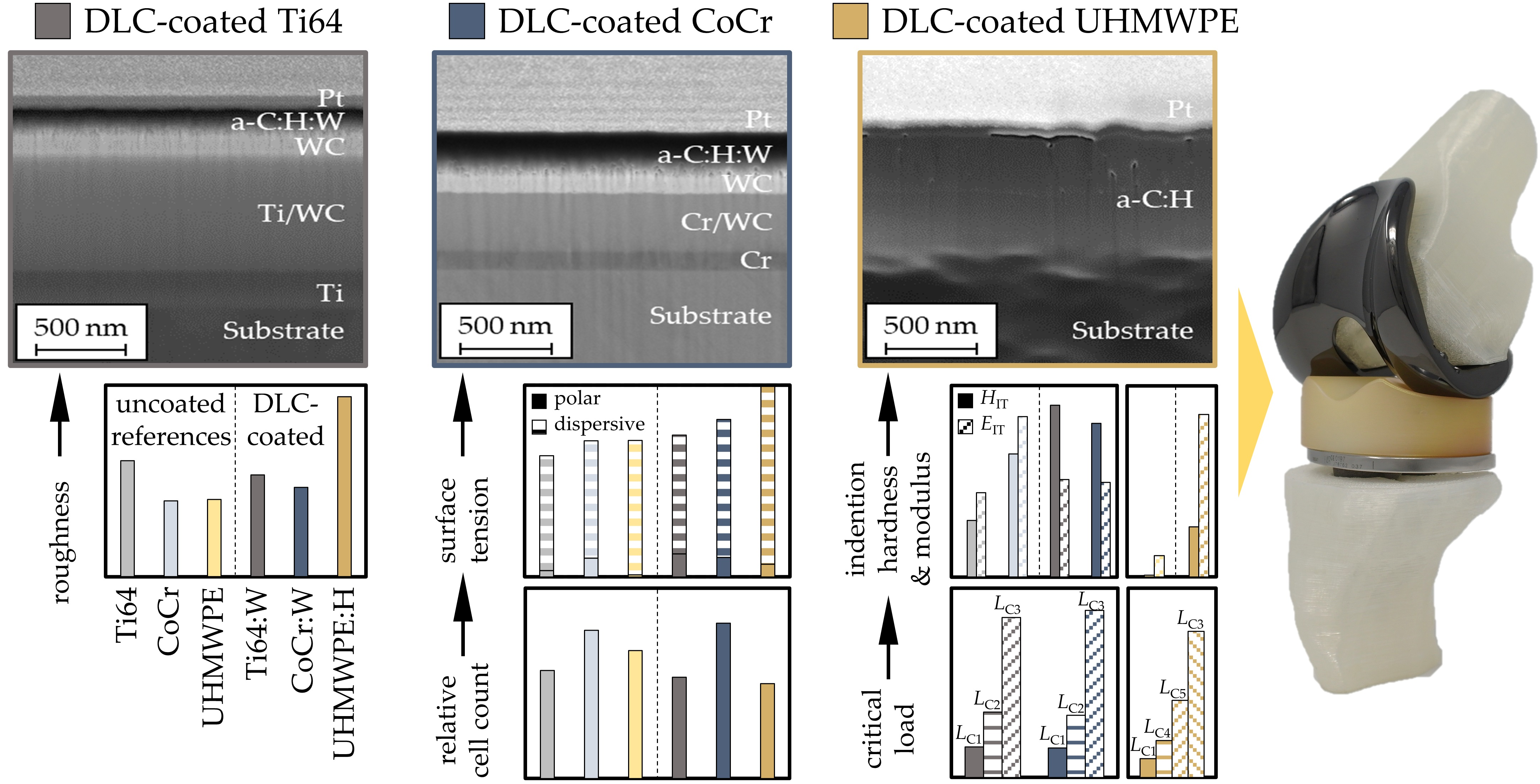
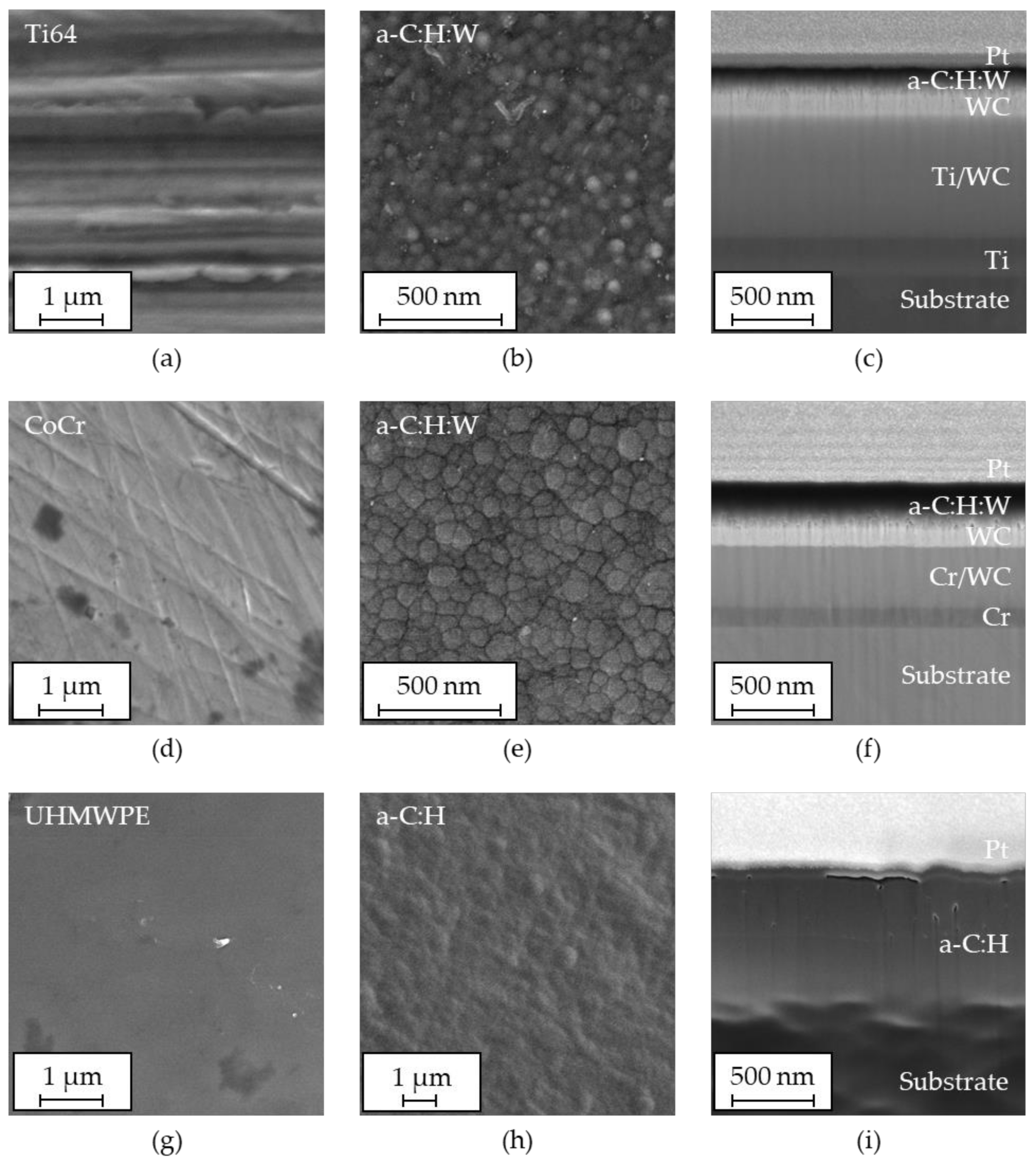
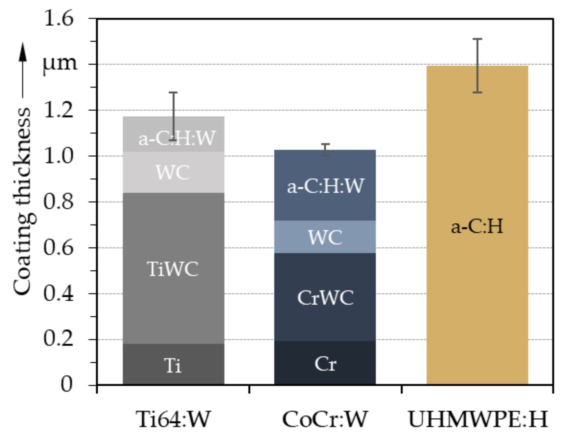
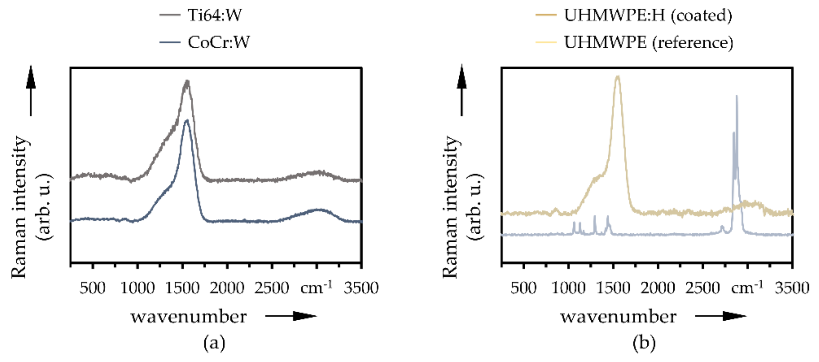
3.1. Coating Topography and Structure
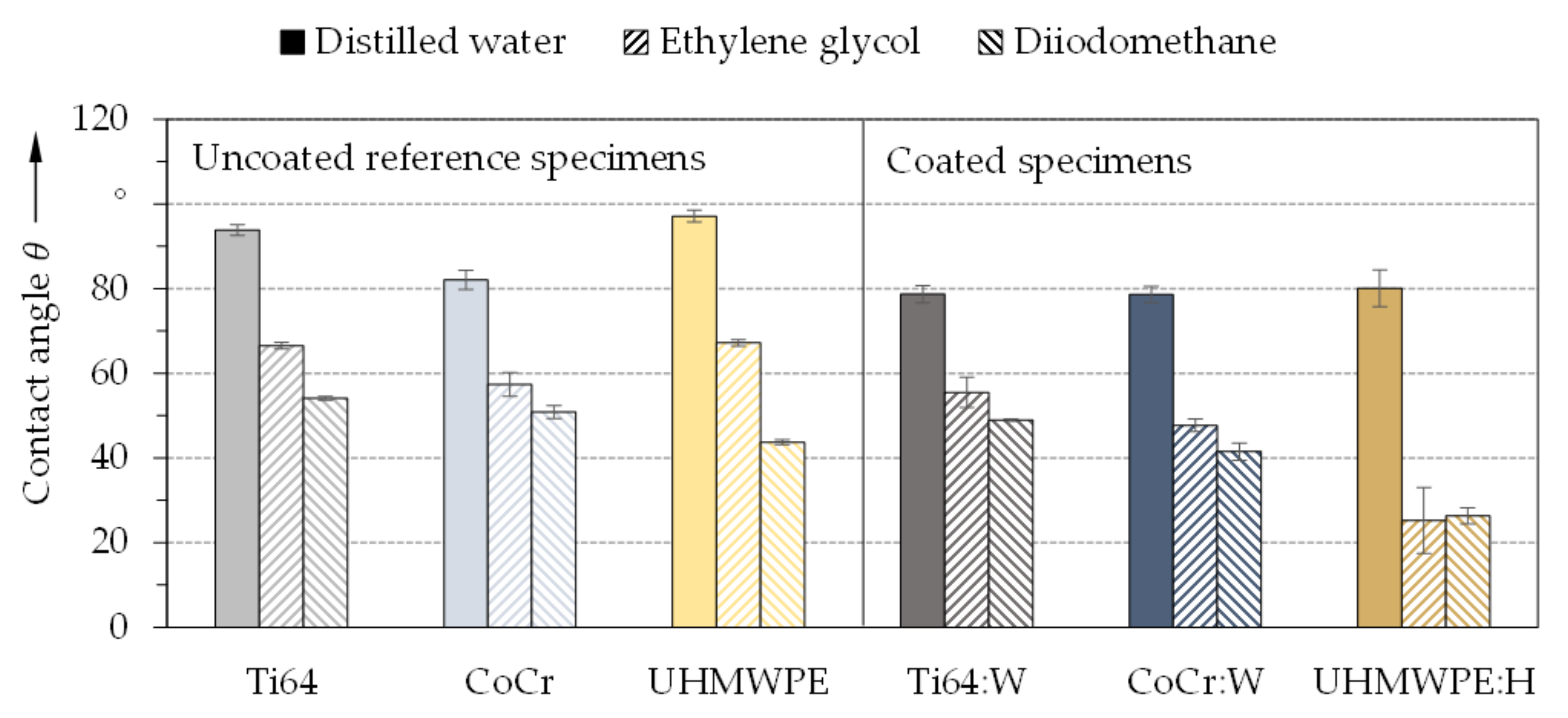
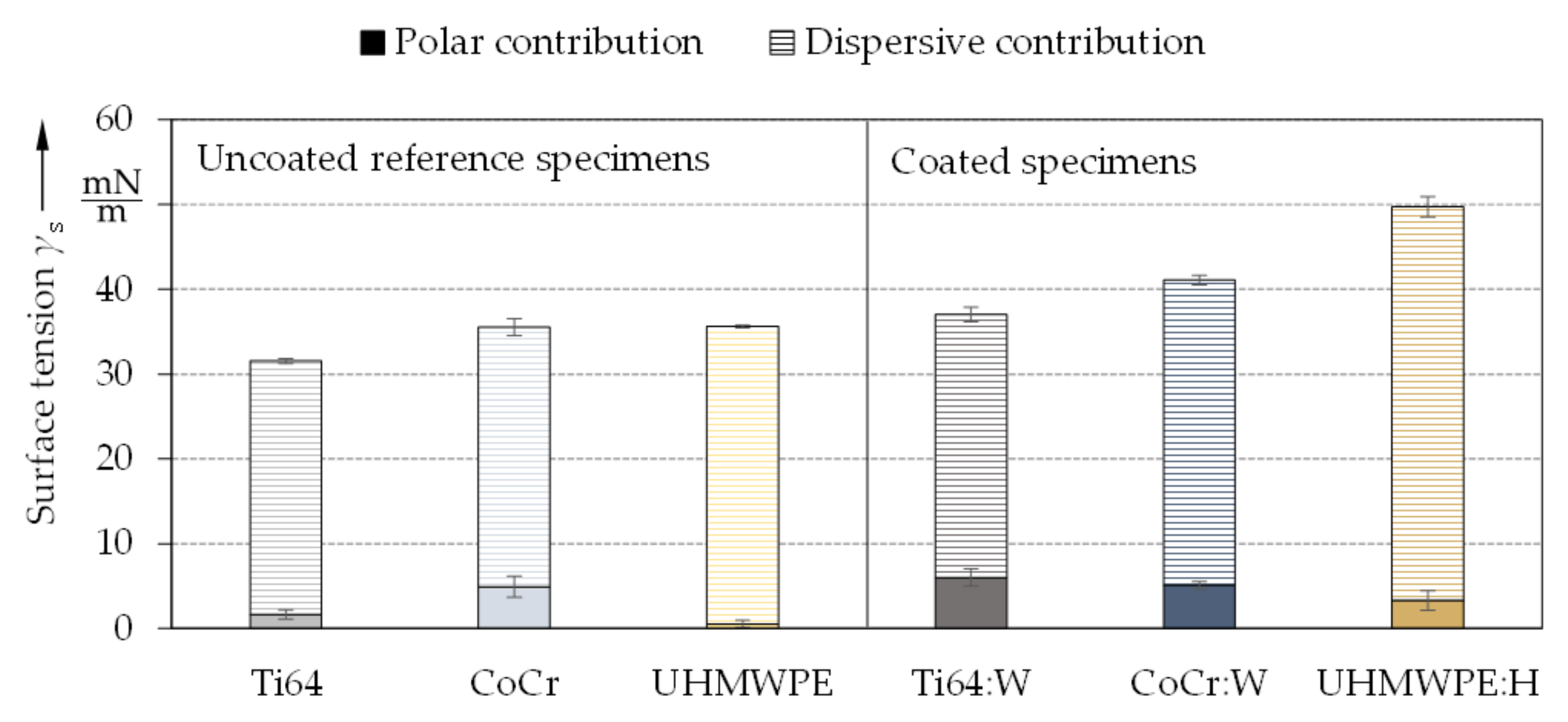
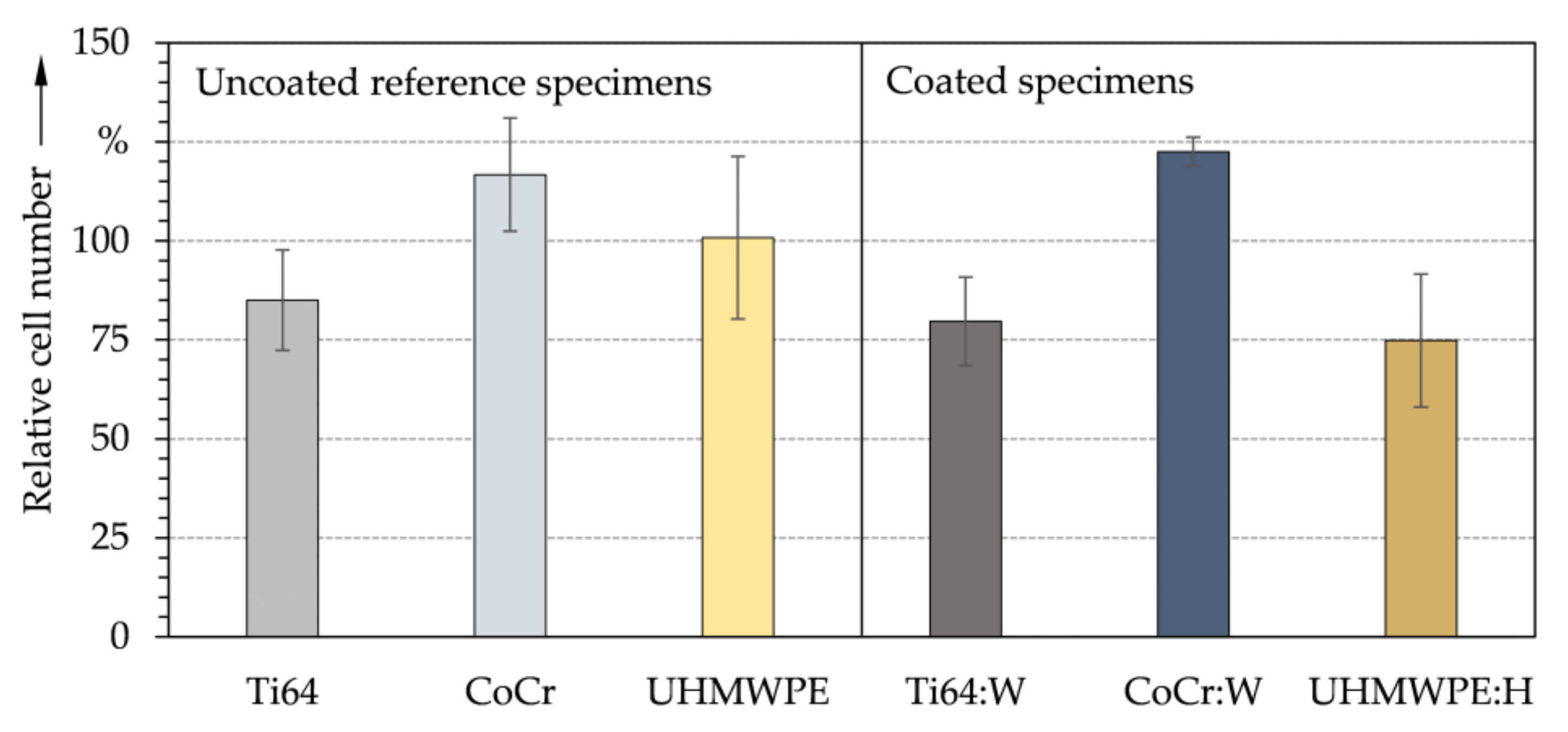
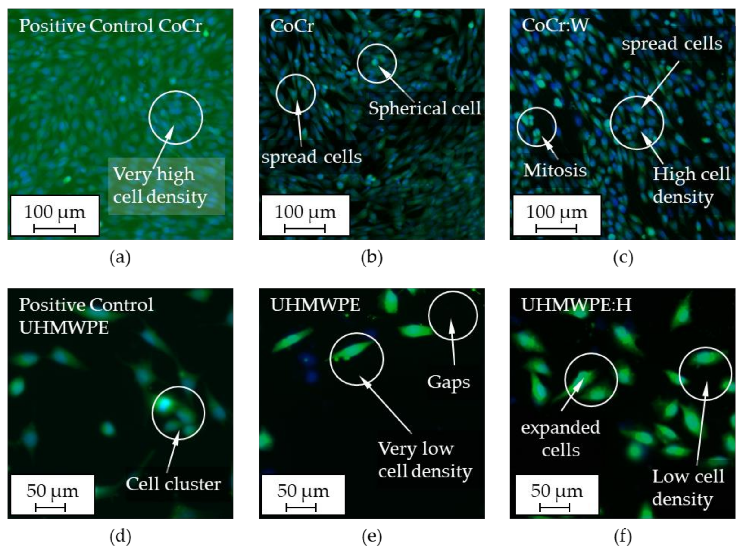
3.2. Chemical Properties and Cytological Interactions
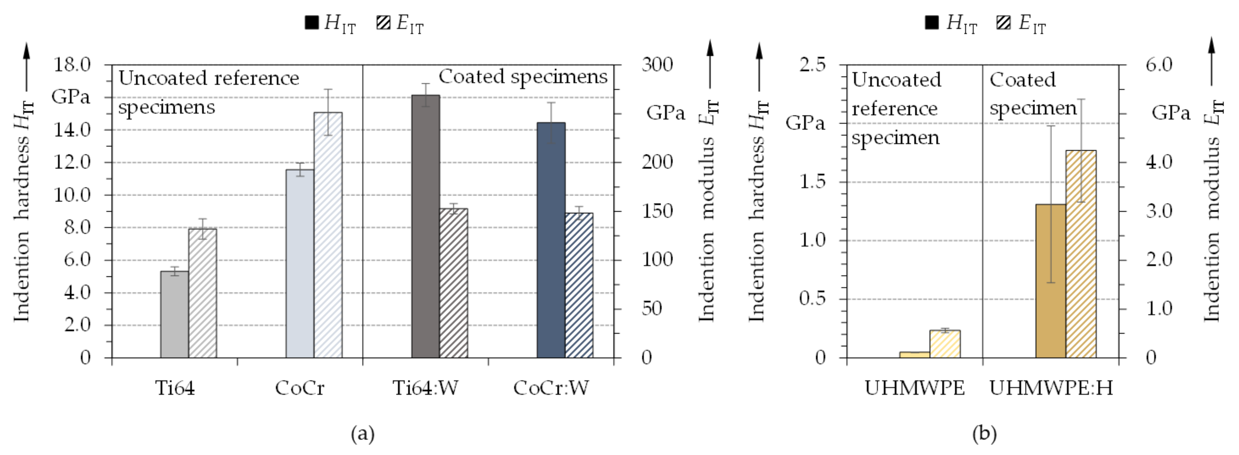
3.3. Mechanical Properties
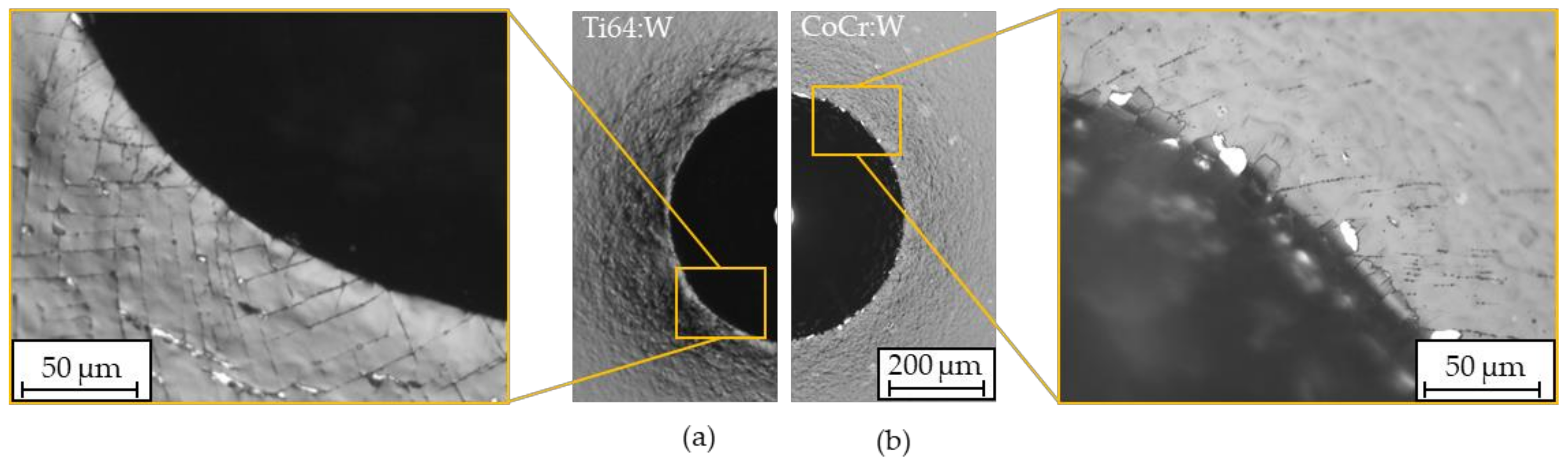
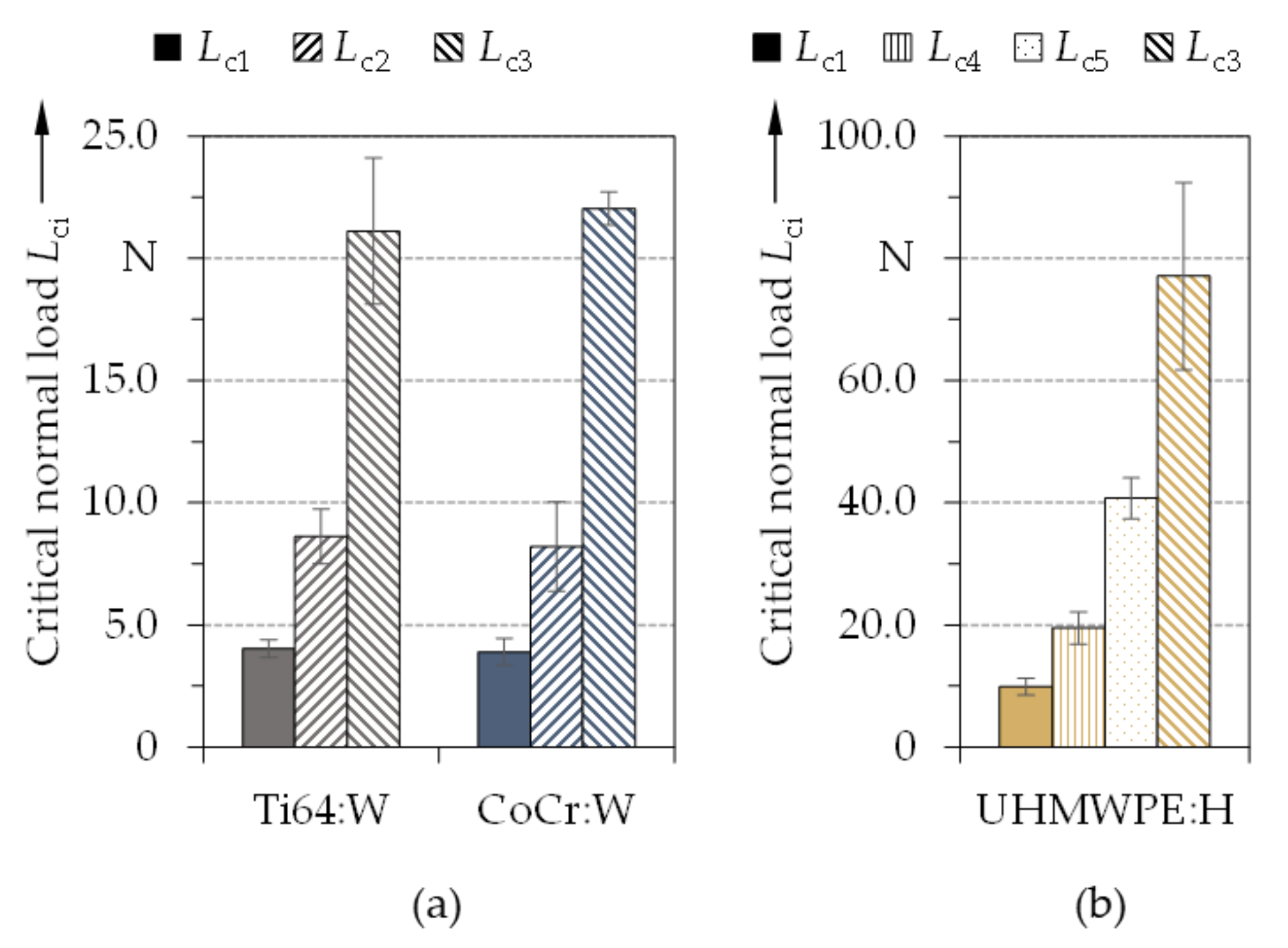
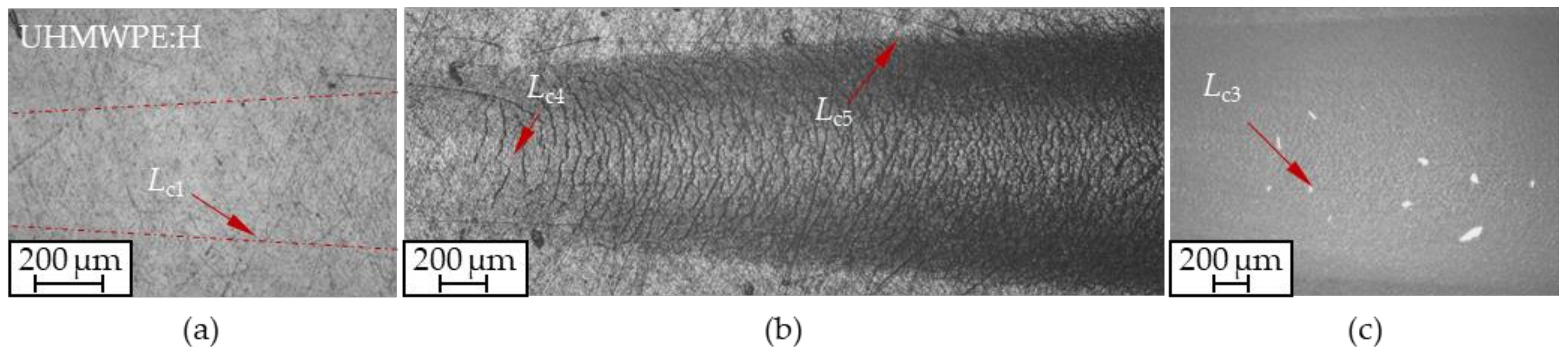
3.4. Adhesion
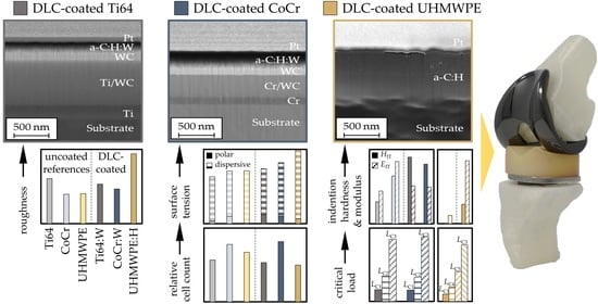
4. Conclusions
- ▪
- The deposited coatings displayed a morphology as well as composition typical for amorphous carbon coatings. The roughness of the coatings was higher than that of the substrates, especially for UHMWPE.
- ▪
- Initial screening with contact angles and surface tensions as well as indirect and direct in vitro biocompatibility studies on DLC coatings comparable to the substrates showed no cytotoxic effects of the surface treatment and confirmed the approach of the biomedical application.
- ▪
- The developed coatings featured excellent mechanical properties with a substantial enhancement of HITx/EITy ratios, indicating favorable biotribological wear behavior.
- ▪
- The adhesion of the coatings to the Ti64, CoCr and UHMWPE substrates can be considered as sufficient for the usage in total knee replacements.
- ▪
- It can be assumed that the amorphous carbon coatings presented in this contribution are able to outperform uncoated metallic-polymeric reference pairings under biotribological stresses. This will be further elaborated in part II of this study [50].
Author Contributions
Funding
Institutional Review Board Statement
Informed Consent Statement
Data Availability Statement
Acknowledgments
Conflicts of Interest
Nomenclature
| EIT | Indentation modulus |
| f | Pulse frequency |
| HF | Adhesion strength class |
| HIT | Indentation hardness |
| ID | D-band Raman intensity |
| IG | G-band Raman intensity |
| Lc,i | Critical normal load |
| pH,i | Maximum Hertzian contact pressure |
| Ra | Average mean roughness |
| Rpk | Reduced peak height |
| Rq | Root-mean-squared roughness |
| RRT | Reverse recovery time |
| s | Scratch path |
| γs | Surface tension |
| θ | Contact angle |
| ν | Poisson’s ratio |
References
- Seidlitz, C.; Kip, M. Einführung in das Indikationsgebiet und Verfahren. In Weißbuch Gelenkersatz: Versorgungssituation bei Endoprothetischen Hüft- und Knieoperationen in Deutschland; Bleß, H.-H., Kip, M., Eds.; Springer: Berlin/Heidelberg, Germany, 2017; pp. 1–15. ISBN 978-3-662-52904-1. [Google Scholar]
- Baumann, B.; Sterner, T.; Rader, C.P. Aseptische Knieprothesenlockerung. In AE-Manual der Endoprothetik; Wirtz, D.C., Ed.; Springer: Heidelberg, Germany; Dordrecht, The Netherlands; London, UK; New York, NY, USA, 2011; pp. 213–226. ISBN 978-3-642-12888-2. [Google Scholar]
- Robertsson, O.; Dahle, A.; Lidgren, L.; Sundberg, M. Swedish Knee Arthroplasty Register; Elvins Grafiska AB: Helsingborg, Sweden, 2020; ISBN 978-91-88017-32-1. [Google Scholar]
- Australian Orthopaedic Association National Joint Replacement Registry. Hip, Knee & Shoulder Arthroplasty: 2020 Annual Report; AOA: Adelaide, Australia, 2020. [Google Scholar]
- Flören, M.; Reichel, H. Implantate. In AE-Manual der Endoprothetik; Wirtz, D.C., Ed.; Springer: Heidelberg, Germany; Dordrecht, The Netherlands; London, UK; New York, NY, USA, 2011; pp. 57–71. ISBN 978-3-642-12888-2. [Google Scholar]
- Evans, J.T.; Walker, R.W.; Evans, J.P.; Blom, A.W.; Sayers, A.; Whitehouse, M.R. How long does a knee replacement last? A systematic review and meta-analysis of case series and national registry reports with more than 15 years of follow-up. Lancet 2019, 393, 655–663. [Google Scholar] [CrossRef]
- Cook, R.; Davidson, P.; Martin, R. More than 80% of total knee replacements can last for 25 years. BMJ 2019, 367, l5680. [Google Scholar] [CrossRef] [PubMed]
- Sundfeldt, M.; Carlsson, L.V.; Johansson, C.B.; Thomsen, P.; Gretzer, C. Aseptic loosening, not only a question of wear: A review of different theories. Acta Orthop. 2006, 77, 177–197. [Google Scholar] [CrossRef] [PubMed]
- Lombardi, A.V.; Berend, K.R.; Adams, J.B. Why knee replacements fail in 2013: Patient, surgeon, or implant? Bone Jt. J. 2014, 96, 101–104. [Google Scholar] [CrossRef] [PubMed]
- Bläsius, K. Endoprothesenatlas KNIE; Steinkopff: Darmstadt, Germany, 2008; ISBN 978-3-7985-1767-7. [Google Scholar]
- Wood, R.J.K. Multifunctional Materials for Tribological Applications; Pan Stanford: Hoboken, NJ, USA, 2015; ISBN 9789814463904. [Google Scholar]
- Hauert, R.; Thorwarth, K.; Thorwarth, G. An overview on diamond-like carbon coatings in medical applications. Surf. Coat. Technol. 2013, 233, 119–130. [Google Scholar] [CrossRef]
- McGeough, J.A. The Engineering of Human Joint Replacements; John Wiley & Sons Ltd.: Chichester, UK, 2013; ISBN 9781118536834. [Google Scholar]
- Czichos, H.; Habig, K.-H. Tribologie-Handbuch; Springer: Wiesbaden, Germany, 2015; ISBN 978-3-8348-1810-2. [Google Scholar]
- Repenning, D. Beschichtungen auf Implantaten. In Ossäre Integration; Springer: Berlin/Heidelberg, Germany, 2006; pp. 53–61. ISBN 978-3-540-22721-2. [Google Scholar]
- Döring, J.; Crackau, M.; Nestler, C.; Welzel, F.; Bertrand, J.; Lohmann, C.H. Characteristics of different cathodic arc deposition coatings on CoCrMo for biomedical applications. J. Mech. Behav. Biomed. Mater. 2019, 97, 212–221. [Google Scholar] [CrossRef] [PubMed]
- Ching, H.A.; Choudhury, D.; Nine, M.J.; Abu Osman, N.A. Effects of surface coating on reducing friction and wear of orthopaedic implants. Sci. Technol. Adv. Mater. 2014, 15, 14402. [Google Scholar] [CrossRef]
- Gotman, I.; Gutmanas, E.Y. Titanium Nitride-Based Coatings on Implantable Medical Devices. Adv. Biomater. Devices Med. 2014, 1, 53–73. [Google Scholar]
- Reich, J.; Hovy, L.; Lindenmaier, H.-L.; Zeller, R.; Schwiesau, J.; Thomas, P.; Grupp, T.M. Präklinische Ergebnisse beschichteter Knieimplantate für Allergiker. Orthopade 2010, 39, 495–502. [Google Scholar] [CrossRef]
- van Hove, R.P.; Sierevelt, I.N.; van Royen, B.J.; Nolte, P.A. Titanium-Nitride Coating of Orthopaedic Implants: A Review of the Literature. Biomed Res. Int. 2015, 2015, 485975. [Google Scholar] [CrossRef]
- Tribe, H.; Malek, S.; Stammers, J.; Ranawat, V.; Skinner, J.A. Advanced wear of an Oxinium™ femoral head implant following polyethylene liner dislocation. Ann. R. Coll. Surg. Engl. 2013, 95, e133–e135. [Google Scholar] [CrossRef]
- Galetz, M.C.; Fleischmann, E.W.; Konrad, C.H.; Schuetz, A.; Glatzel, U. Abrasion resistance of oxidized zirconium in comparison with CoCrMo and titanium nitride coatings for artificial knee joints. J. Biomed. Mater. Res. Part B Appl. Biomater. 2010, 93, 244–251. [Google Scholar] [CrossRef]
- Hauert, R. A review of modified DLC coatings for biological applications. Diam. Relat. Mater. 2003, 12, 583–589. [Google Scholar] [CrossRef]
- Dorner-Reisel, A.; Schürer, C.; Nischan, C.; Seidel, O.; Müller, E. Diamond-like carbon: Alteration of the biological acceptance due to Ca–O incorporation. Thin Solid Films 2002, 420–421, 263–268. [Google Scholar] [CrossRef]
- Dorner-Reisel, A.; Schürer, C.; Klemm, V.; Irmer, G.; Müller, E. Nano- and microstructure of diamond-like carbon films modified by Ca–O incorporation. Diam. Relat. Mater. 2003, 12, 1030–1033. [Google Scholar] [CrossRef]
- Hauert, R.; Müller, U. An overview on tailored tribological and biological behavior of diamond-like carbon. Diam. Relat. Mater. 2003, 12, 171–177. [Google Scholar] [CrossRef]
- Harrasser, N.; Jüssen, S.; Obermeir, A.; Kmeth, R.; Stritzker, B.; Gollwitzer, H.; Burgkart, R. Antibacterial potency of different deposition methods of silver and copper containing diamond-like carbon coated polyethylene. Biomater. Res. 2016, 20, 17. [Google Scholar] [CrossRef]
- Roy, R.K.; Lee, K.-R. Biomedical applications of diamond-like carbon coatings: A review. J. Biomed. Mater. Res. Part B Appl. Biomater. 2007, 83, 72–84. [Google Scholar] [CrossRef]
- Sánchez-López, J.C.; Fernández, A. Doping and Alloying Effects on DLC Coatings. In Tribology of Diamond-Like Carbon Films; Donnet, C., Erdemir, A., Eds.; Springer: Boston, MA, USA, 2008; pp. 311–338. ISBN 978-0-387-30264-5. [Google Scholar]
- Schroeder, A.; Francz, G.; Bruinink, A.; Hauert, R.; Mayer, J.; Wintermantel, E. Titanium containing amorphous hydrogenated carbon films (a-C:H/Ti): Surface analysis and evaluation of cellular reactions using bone marrow cell cultures in vitro. Biomaterials 2000, 21, 449–456. [Google Scholar] [CrossRef]
- Fontaine, J.; Donnet, C.; Erdemir, A. Fundamentals of the Tribology of DLC Coatings. In Tribology of Diamond-Like Carbon Films; Donnet, C., Erdemir, A., Eds.; Springer: Boston, MA, USA, 2008; pp. 139–154. ISBN 978-0-387-30264-5. [Google Scholar]
- Pauleau, Y. Residual Stresses in DLC Films and Adhesion to Various Substrates. In Tribology of Diamond-Like Carbon Films; Donnet, C., Erdemir, A., Eds.; Springer: Boston, MA, USA, 2008; pp. 102–136. ISBN 978-0-387-30264-5. [Google Scholar]
- Dorner-Reisel, A.; Schürer, C.; Irmer, G.; Simon, F.; Nischan, C.; Müller, E. Diamond-like carbon coatings with Ca-O-incorporation for improved biological acceptance. Anal. Bioanal. Chem. 2002, 374, 753–755. [Google Scholar] [CrossRef]
- Escudeiro, A.; Wimmer, M.A.; Polcar, T.; Cavaleiro, A. Tribological behavior of uncoated and DLC-coated CoCr and Ti-alloys in contact with UHMWPE and PEEK counterbodies. Tribol. Int. 2015, 89, 97–104. [Google Scholar] [CrossRef]
- Weikert, T.; Wartzack, S.; Baloglu, M.V.; Willner, K.; Gabel, S.; Merle, B.; Pineda, F.; Walczak, M.; Marian, M.; Rosenkranz, A.; et al. Evaluation of the surface fatigue behavior of amorphous carbon coatings through cyclic nanoindentation. Surf. Coat. Technol. 2021, 407, 126769. [Google Scholar] [CrossRef]
- Mang, T.; Bobzin, K.; Bartels, T. Industrial Tribology: Tribosystems, Friction, Wear and Surface Engineering, Lubrication, 4th ed.; Wiley-VCH: Hoboken, NJ, USA, 2010; ISBN 978-3-527-32057-8. [Google Scholar]
- Österle, W.; Klaffke, D.; Griepentrog, M.; Gross, U.; Kranz, I.; Knabe, C. Potential of wear resistant coatings on Ti–6Al–4V for artificial hip joint bearing surfaces. Wear 2008, 264, 505–517. [Google Scholar] [CrossRef]
- Avelar-Batista, J.C.; Spain, E.; Fuentes, G.G.; Sola, A.; Rodriguez, R.; Housden, J. Triode plasma nitriding and PVD coating: A successful pre-treatment combination to improve the wear resistance of DLC coatings on Ti6Al4V alloy. Surf. Coat. Technol. 2006, 201, 4335–4340. [Google Scholar] [CrossRef]
- Oñate, J.I.; Comin, M.; Braceras, I.; Garcia, A.; Viviente, J.L.; Brizuela, M.; Garagorri, N.; Peris, J.L.; Alava, J.I. Wear reduction effect on ultra-high-molecular-weight polyethylene by application of hard coatings and ion implantation on cobalt chromium alloy, as measured in a knee wear simulation machine. Surf. Coat. Technol. 2001, 142–144, 1056–1062. [Google Scholar] [CrossRef]
- Strondl, C.; Carvalho, N.M.; de Hosson, J.; Krug, T.G. Influence of energetic ion bombardment on W-C:H coatings deposited with W and WC targets. Surf. Coat. Technol. 2005, 200, 1142–1146. [Google Scholar] [CrossRef]
- Love, C.A.; Cook, R.B.; Harvey, T.J.; Dearnley, P.A.; Wood, R. Diamond like carbon coatings for potential application in biological implants—A review. Tribol. Int. 2013, 63, 141–150. [Google Scholar] [CrossRef]
- Rothammer, B.; Weikert, T.; Tremmel, S.; Wartzack, S. Tribological behavior of amorphous carbon coatings on metals for total knee arthroplasty. Tribol. Schmier. 2019, 66, 15–24. [Google Scholar] [CrossRef]
- Hetzner, H.; Schaufler, J.; Tremmel, S.; Durst, K.; Wartzack, S. Failure mechanisms of a tungsten-modified hydrogenated amorphous carbon coating in load-scanning tests. Surf. Coat. Technol. 2012, 212, 46–54. [Google Scholar] [CrossRef]
- Peuster, M. Biocompatibility of corroding tungsten coils: In vitro assessment of degradation kinetics and cytotoxicity on human cells. Biomaterials 2003, 24, 4057–4061. [Google Scholar] [CrossRef]
- Alakoski, E.; Tiainen, V.-M.; Soininen, A.; Konttinen, Y.T. Load-bearing biomedical applications of diamond-like carbon coatings—Current status. Open Orthop. J. 2008, 2, 43–50. [Google Scholar] [CrossRef]
- Dorner-Reisel, A.; Gärtner, G.; Reisel, G.; Irmer, G. Diamond-like carbon films for polyethylene femoral parts: Raman and FT-IR spectroscopy before and after incubation in simulated body liquid. Anal. Bioanal. Chem. 2008, 390, 1487–1493. [Google Scholar] [CrossRef]
- He, F.F.; Bai, W.Q.; Li, L.L.; Wang, X.L.; Xie, Y.J.; Jin, G.; Tu, J.P. Enhancement of adhesion by a transition layer: Deposition of a-C film on ultrahigh molecular weight polyethylene (UHMWPE) by magnetron sputtering. Appl. Surf. Sci. 2016, 364, 280–287. [Google Scholar] [CrossRef]
- Kyzioł, K.; Oczkowska, J.; Kottfer, D.; Klich, M.; Kaczmarek, Ł.; Kyzioł, A.; Grzesik, Z. Physicochemical and Biological Activity Analysis of Low-Density Polyethylene Substrate Modified by Multi-Layer Coatings Based on DLC Structures, Obtained Using RF CVD Method. Coatings 2018, 8, 135. [Google Scholar] [CrossRef]
- Hsieh, J.H.; Li, C.; Lin, Y.C.; Chiu, C.H.; Hu, C.C.; Chang, Y.H. Antibacteria and anti-wear TaN–(Ag, Cu) nanocomposite thin films deposited on polyether ether ketone. Thin Solid Films 2015, 584, 277–282. [Google Scholar] [CrossRef]
- Rothammer, B.; Marian, M.; Neusser, K.; Bartz, M.; Böhm, T.; Krauß, S.; Schroeder, S.; Uhler, M.; Thiele, S.; Merle, B.; et al. Amorphous Carbon Coatings for Total Knee Replacements—Part II: Tribological Behavior. Polymers 2021, 13, 1880. [Google Scholar] [CrossRef]
- ISO. 5834-2:2019 Implants for Surgery—Ultra-High-Molecular-Weight Polyethylene—Part 2: Moulded Forms; ISO: Geneva, Switzerland, 2019. [Google Scholar]
- ISO. 5832-12:2019-02 Implants for Surgery—Metallic Materials—Part 12: Wrought Cobalt-Chromium-Molybdenum Alloy; ISO: Geneva, Switzerland, 2019. [Google Scholar]
- ISO. 5832-3:2016 Implants for Surgery—Metallic Materials—Part 3: Wrought Titanium 6-Aluminium 4-Vanadium Alloy; ISO: Geneva, Switzerland, 2016. [Google Scholar]
- DIN EN ISO. 4287:2010-07 Geometrical Product Specifications (GPS)—Surface Texture: Profile Method—Terms, Definitions and Surface Texture Parameters; DIN: Berlin, Germany, 2010. [Google Scholar]
- DIN EN ISO. 4288:1998-04 Geometrical Product Specifications (GPS)—Surface Texture: Profile Method—Rules and Procedures for the Assessment of Surface Texture; DIN: Berlin, Germany, 1998. [Google Scholar]
- DIN EN ISO. 13565-1:1998-04 Geometrical Product Specifications (GPS)—Surface Texture: Profile Method—Surfaces Having Stratified Functional Properties—Part 1: Filtering and General Measurement Conditions; DIN: Berlin, Germany, 1998. [Google Scholar]
- DIN EN ISO. 13565-2:1998-04 Geometrical Product Specifications (GPS)—Surface Texture: Profile Method—Surfaces Having Stratified Functional Properties—Part 2: Height Characterization Using the Linear Material Ratio Curve; DIN: Berlin, Germany, 1998. [Google Scholar]
- DIN EN ISO. 26423:2016-11 Fine Ceramics (Advanced Ceramics, Advanced Technical Ceramics)—Determination of Coating Thickness by Crater-Grinding Method; DIN: Berlin, Germany, 2016. [Google Scholar]
- DIN EN. 828:2013-04 Adhesives—Wettability—Determination by Measurement of Contact Angle and Surface Free Energy of Solid Surface; DIN: Berlin, Germany, 2013. [Google Scholar]
- Owens, D.K.; Wendt, R.C. Estimation of the surface free energy of polymers. J. Appl. Polym. Sci. 1969, 13, 1741–1747. [Google Scholar] [CrossRef]
- Rabel, W. Einige Aspekte der Benetzungstheorie und ihre Anwendung auf die Untersuchung und Veränderung der Oberflächeneigenschaften von Polymeren. Farbe Lack 1971, 77, 997–1005. [Google Scholar]
- Kaelble, D.H. Dispersion-Polar Surface Tension Properties of Organic Solids. J. Adhes. 1970, 2, 66–81. [Google Scholar] [CrossRef]
- DIN EN ISO. 10993-1:2017-04 Biological Evaluation of Medical Devices—Part 1: Evaluation and Testing Within a Risk Management Process; DIN: Berlin, Germany, 2017. [Google Scholar]
- DIN EN ISO. 10993-5:1999-11 Biological Evaluation of Medical Devices—Part 5: Tests for Cytotoxicity: In Vitro-Methods; DIN: Berlin, Germany, 1999. [Google Scholar]
- Oliver, W.C.; Pharr, G.M. An improved technique for determining hardness and elastic modulus using load and displacement sensing indentation experiments. J. Mater. Res. 1992, 7, 1564–1583. [Google Scholar] [CrossRef]
- Oliver, W.C.; Pharr, G.M. Measurement of hardness and elastic modulus by instrumented indentation: Advances in understanding and refinements to methodology. J. Mater. Res. 2004, 19, 3–20. [Google Scholar] [CrossRef]
- DIN EN ISO. 14577-1:2015-11 Metallic Materials—Instrumented Indentation Test for Hardness and Materials Parameters—Part 1: Test Method; DIN: Berlin, Germany, 2015. [Google Scholar]
- DIN EN ISO. 14577-4:2017-04 Metallic Materials—Instrumented Indentation Test for Hardness and Materials Parameters—Part 4: Test Method for Metallic and Non-Metallic Coatings; DIN: Berlin, Germany, 2017. [Google Scholar]
- Jiang, X.; Reichelt, K.; Stritzker, B. The hardness and Young’s modulus of amorphous hydrogenated carbon and silicon films measured with an ultralow load indenter. J. Appl. Phys. 1989, 66, 5805–5808. [Google Scholar] [CrossRef]
- Cho, S.-J.; Lee, K.-R.; Yong Eun, K.; Hee Hahn, J.; Ko, D.-H. Determination of elastic modulus and Poisson’s ratio of diamond-like carbon films. Thin Solid Films 1999, 341, 207–210. [Google Scholar] [CrossRef]
- Köster, W. Die Poisson’sche Konstante der Metalle. Appl. Sci. Res. 1954, 4, 329–336. [Google Scholar] [CrossRef]
- DIN EN ISO. 6508-1:2016-12 Metallic Materials—Rockwell Hardness Test—Part 1: Test Method; DIN: Berlin, Germany, 2016. [Google Scholar]
- DIN EN ISO. 26443:2016-09 Fine Ceramics (Advanced Ceramics, Advanced Technical Ceramics)—Rockwell Indentation Test for Evaluation of Adhesion of Ceramic Coatings; DIN: Berlin, Germany, 2016. [Google Scholar]
- DIN. 4856:2018-02 Carbon-Based Films and Other Hard Coatings—Rockwell Penetration Test to Evaluate the Adhesion; DIN: Berlin, Germany, 2018. [Google Scholar]
- DIN EN ISO. 6508-2:2015-06 Metallic Materials—Rockwell Hardness Test—Part 2: Verification and Calibration of Testing Machines and Indenters; DIN: Berlin, Germany, 2015. [Google Scholar]
- DIN EN ISO. 20502:2016-11 Fine Ceramics (Advanced Ceramics, Advanced Technical Ceramics)—Determination of Adhesion of Ceramic Coatings by Scratch Testing; DIN: Berlin, Germany, 2016. [Google Scholar]
- Sander, T.; Tremmel, S.; Wartzack, S. A modified scratch test for the mechanical characterization of scratch resistance and adhesion of thin hard coatings on soft substrates. Surf. Coat. Technol. 2011, 206, 1873–1878. [Google Scholar] [CrossRef]
- Jaber, S.A.; Ruggiero, A.; Battaglia, S.; Affatato, S. On the roughness measurement on knee prostheses. Int. J. Artif. Organs 2015, 38, 39–44. [Google Scholar] [CrossRef]
- ISO. 7207-2 Implants for Surgery—Components for Partial and Total Knee Joint Prostheses—Part 2: Articulating Surfaces Made of Metal, Ceramic and Plastics Materials; ISO: Geneva, Switzerland, 2011. [Google Scholar]
- Flannery, M.; Jones, E.; Birkinshaw, C. Analysis of wear and friction of total knee replacements part II: Friction and lubrication as a function of wear. Wear 2008, 265, 1009–1016. [Google Scholar] [CrossRef]
- Nečas, D.; Vrbka, M.; Marian, M.; Rothammer, B.; Tremmel, S.; Wartzack, S.; Galandáková, A.; Gallo, J.; Wimmer, M.A.; Křupka, I.; et al. Towards the understanding of lubrication mechanisms in total knee replacements—Part I: Experimental investigations. Tribol. Int. 2021, 156, 106874. [Google Scholar] [CrossRef]
- Keller, J.C.; Schneider, G.B.; Stanford, C.M.; Kellogg, B. Effects of implant microtopography on osteoblast cell attachment. Implant Dent. 2003, 12, 175–181. [Google Scholar] [CrossRef]
- Degasne, I.; Baslé, M.F.; Demais, V.; Huré, G.; Lesourd, M.; Grolleau, B.; Mercier, L.; Chappard, D. Effects of roughness, fibronectin and vitronectin on attachment, spreading, and proliferation of human osteoblast-like cells (Saos-2) on titanium surfaces. Calcif. Tissue Int. 1999, 64, 499–507. [Google Scholar] [CrossRef]
- Ezugwu, E.O.; Wang, Z.M. Titanium alloys and their machinability—A review. J. Mater. Process. Technol. 1997, 68, 262–274. [Google Scholar] [CrossRef]
- Hughes, J.I.; Sharman, A.R.C.; Ridgway, K. The Effect of Cutting Tool Material and Edge Geometry on Tool Life and Workpiece Surface Integrity. Proc. Inst. Mech. Eng. Part B J. Eng. Manuf. 2006, 220, 93–107. [Google Scholar] [CrossRef]
- Sun, J.; Guo, Y.B. A comprehensive experimental study on surface integrity by end milling Ti–6Al–4V. J. Mater. Process. Technol. 2009, 209, 4036–4042. [Google Scholar] [CrossRef]
- Moussaoui, K.; Mousseigne, M.; Senatore, J.; Chieragatti, R.; Monies, F. Influence of milling on surface integrity of Ti6Al4V—study of the metallurgical characteristics: Microstructure and microhardness. Int. J. Adv. Manuf. Technol. 2013, 67, 1477–1489. [Google Scholar] [CrossRef]
- Cantero, J.L.; Tardío, M.M.; Canteli, J.A.; Marcos, M.; Miguélez, M.H. Dry drilling of alloy Ti–6Al–4V. Int. J. Mach. Tools Manuf. 2005, 45, 1246–1255. [Google Scholar] [CrossRef]
- Che-Haron, C.H.; Jawaid, A. The effect of machining on surface integrity of titanium alloy Ti–6% Al–4% V. J. Mater. Process. Technol. 2005, 166, 188–192. [Google Scholar] [CrossRef]
- Shokrani, A.; Dhokia, V.; Newman, S.T. Environmentally conscious machining of difficult-to-machine materials with regard to cutting fluids. Int. J. Mach. Tools Manuf. 2012, 57, 83–101. [Google Scholar] [CrossRef]
- Zaman, H.A.; Sharif, S.; Kim, D.-W.; Idris, M.H.; Suhaimi, M.A.; Tumurkhuyag, Z. Machinability of Cobalt-based and Cobalt Chromium Molybdenum Alloys—A Review. Procedia Manuf. 2017, 11, 563–570. [Google Scholar] [CrossRef]
- Moharrami, N.; Langton, D.J.; Sayginer, O.; Bull, S.J. Why does titanium alloy wear cobalt chrome alloy despite lower bulk hardness: A nanoindentation study? Thin Solid Films 2013, 549, 79–86. [Google Scholar] [CrossRef]
- Patel, B.; Favaro, G.; Inam, F.; Reece, M.J.; Angadji, A.; Bonfield, W.; Huang, J.; Edirisinghe, M. Cobalt-based orthopaedic alloys: Relationship between forming route, microstructure and tribological performance. Mater. Sci. Eng. C 2012, 32, 1222–1229. [Google Scholar] [CrossRef]
- Azam, M.U.; Samad, M.A. Tribological Evaluation of a UHMWPE Hybrid Nanocomposite Coating Reinforced With Nanoclay and Carbon Nanotubes Under Dry Conditions. J. Tribol. Trans. ASME 2018, 140. [Google Scholar] [CrossRef]
- Bertoluzza, A.; Fagnano, C.; Rossi, M.; Tinti, A.; Cacciari, G.L. Micro-Raman spectroscopy for the crystallinity characterization of UHMWPE hip cups run on joint simulators. J. Mol. Struct. 2000, 521, 89–95. [Google Scholar] [CrossRef]
- Kyomoto, M.; Miwa, Y.; Pezzotti, G. Strain in UHMWPE for orthopaedic use studied by Raman microprobe spectroscopy. J. Biomater. Sci. Polym. Ed. 2007, 18, 165–178. [Google Scholar] [CrossRef]
- Cheng, B.; Duan, H.; Chen, S.; Shang, H.; Li, J.; Shao, T. Phase morphology and tribological properties of PI/UHMWPE blend composites. Polymer 2020, 202, 122658. [Google Scholar] [CrossRef]
- Ferrari, A.C.; Robertson, J. Resonant Raman spectroscopy of disordered, amorphous, and diamondlike carbon. Phys. Rev. B 2001, 64. [Google Scholar] [CrossRef]
- Weinberg, M.D. Distribution of stars in the disk. In Back to the Galaxy, AIP Conference Proceedings, College Park, MD, USA, 12−14 October 1992; American Institute of Physisc: College Park, MD, USA, 1992; pp. 347–358. [Google Scholar]
- Chang, H.-C.; Lin, J.-C.; Wu, J.-Y.; Chen, K.-H. Infrared spectroscopy and vibrational relaxation of CHx and CDx stretches on synthetic diamond nanocrystal surfaces. J. Phys. Chem. 1995, 99, 11081–11088. [Google Scholar] [CrossRef]
- Ferrari, A.C.; Robertson, J. Raman spectroscopy of amorphous, nanostructured, diamond-like carbon, and nanodiamond. Philos. Trans. A Math. Phys. Eng. Sci. 2004, 362, 2477–2512. [Google Scholar] [CrossRef]
- Nakamura, M.; Takagawa, Y.; Miura, K.; Kobata, J.; Zhu, W.; Nishiike, N.; Arao, K.; Marin, E.; Pezzotti, G. Structural alteration induced by substrate bias voltage variation in diamond-like carbon films fabricated by unbalanced magnetron sputtering. Diam. Relat. Mater. 2018, 90, 214–220. [Google Scholar] [CrossRef]
- Cui, W.G.; Lai, Q.B.; Zhang, L.; Wang, F.M. Quantitative measurements of sp3 content in DLC films with Raman spectroscopy. Surf. Coat. Technol. 2010, 205, 1995–1999. [Google Scholar] [CrossRef]
- Menzies, K.L.; Jones, L. The impact of contact angle on the biocompatibility of biomaterials. Optom. Vis. Sci. 2010, 87, 387–399. [Google Scholar] [CrossRef] [PubMed]
- Hinüber, C.; Kleemann, C.; Friederichs, R.J.; Haubold, L.; Scheibe, H.J.; Schuelke, T.; Boehlert, C.; Baumann, M.J. Biocompatibility and mechanical properties of diamond-like coatings on cobalt-chromium-molybdenum steel and titanium-aluminum-vanadium biomedical alloys. J. Biomed. Mater. Res. A 2010, 95, 388–400. [Google Scholar] [CrossRef] [PubMed]
- Nakae, H.; Inui, R.; Hirata, Y.; Saito, H. Effects of surface roughness on wettability. Acta Mater. 1998, 46, 2313–2318. [Google Scholar] [CrossRef]
- Reisel, G.; Dorner-Reisel, A. Hydrogen containing DLC coatings on UHMW-PE deposited by r.f.-PECVD. Diam. Relat. Mater. 2007, 16, 1370–1373. [Google Scholar] [CrossRef]
- Catena, A.; Agnello, S.; Rösken, L.M.; Bergen, H.; Recktenwald, E.; Bernsmann, F.; Busch, H.; Cannas, M.; Gelardi, F.M.; Hahn, B.; et al. Characteristics of industrially manufactured amorphous hydrogenated carbon (a-C:H) depositions on high-density polyethylene. Carbon 2016, 96, 661–671. [Google Scholar] [CrossRef]
- Altankov, G.; Groth, T. Reorganization of substratum-bound fibronectin on hydrophilic and hydrophobic materials is related to biocompatibility. J. Mater. Sci. Mater. Med. 1994, 5, 732–737. [Google Scholar] [CrossRef]
- Catena, A.; Guo, Q.; Kunze, M.R.; Agnello, S.; Gelardi, F.M.; Wehner, S.; Fischer, C.B. Morphological and Chemical Evolution of Gradually Deposited Diamond-Like Carbon Films on Polyethylene Terephthalate: From Subplantation Processes to Structural Reorganization by Intrinsic Stress Release Phenomena. ACS Appl. Mater. Interfaces 2016, 8, 10636–10646. [Google Scholar] [CrossRef]
- Shi, X.; Wang, Q.; Xu, L.; Ge, S.; Wang, C. Hydrogenated diamond-like carbon film deposited on UHMWPE by RF-PECVD. Appl. Surf. Sci. 2009, 255, 8246–8251. [Google Scholar] [CrossRef]
- Liu, X.; Lim, J.Y.; Donahue, H.J.; Dhurjati, R.; Mastro, A.M.; Vogler, E.A. Influence of substratum surface chemistry/energy and topography on the human fetal osteoblastic cell line hFOB 1.19: Phenotypic and genotypic responses observed in vitro. Biomaterials 2007, 28, 4535–4550. [Google Scholar] [CrossRef]
- Vogler, E.A. Structure and reactivity of water at biomaterial surfaces. Adv. Colloid Interface Sci. 1998, 74, 69–117. [Google Scholar] [CrossRef]
- Vogler, E.A. Water and the acute biological response to surfaces. J. Biomater. Sci. Polym. Ed. 1999, 10, 1015–1045. [Google Scholar] [CrossRef]
- Quirynen, M.; Bollen, C.M. The influence of surface roughness and surface-free energy on supra- and subgingival plaque formation in man. A review of the literature. J. Clin. Periodontol. 1995, 22, 1–14. [Google Scholar] [CrossRef]
- Hallab, N.J.; Bundy, K.J.; O’Connor, K.; Moses, R.L.; Jacobs, J.J. Evaluation of metallic and polymeric biomaterial surface energy and surface roughness characteristics for directed cell adhesion. Tissue Eng. 2001, 7, 55–71. [Google Scholar] [CrossRef]
- Van der Valk, P.; van Pelt, A.W.; Busscher, H.J.; de Jong, H.P.; Wildevuur, C.R.; Arends, J. Interaction of fibroblasts and polymer surfaces: Relationship between surface free energy and fibroblast spreading. J. Biomed. Mater. Res. 1983, 17, 807–817. [Google Scholar] [CrossRef]
- Mansano, R.D.; Ruas, R.; Mousinho, A.P.; Zambom, L.S.; Pinto, T.; Amoedo, L.H.; Massi, M. Use of diamond-like carbon with tungsten (W-DLC) films as biocompatible material. Surf. Coat. Technol. 2008, 202, 2813–2816. [Google Scholar] [CrossRef]
- Haider, H. UHMWPE Biomaterials Handbook; Elsevier: Amsterdam, The Netherlands, 2016; ISBN 9780323354011. [Google Scholar]
- Wintermantel, E.; Ha, S.-W. Medizintechnik; Springer: Berlin/Heidelberg, Germany, 2009; ISBN 978-3-540-93935-1. [Google Scholar]
- Detsch, R.; Guillon, O.; Wondraczek, L.; Boccaccini, A.R. Initial Attatchment of rMSC and MG-63 Cells on Patterned Bioglass® Substrates. Adv. Eng. Mater. 2012, 14, B38–B44. [Google Scholar] [CrossRef]
- Traisnel, M.; Le Maguer, D.; Hildebrand, H.F.; Iost, A. Corrosion of surgical implants. Clin. Mater. 1990, 5, 309–318. [Google Scholar] [CrossRef]
- Leyland, A.; Matthews, A. On the significance of the H/E ratio in wear control: A nanocomposite coating approach to optimised tribological behaviour. Wear 2000, 246, 1–11. [Google Scholar] [CrossRef]
- Escudeiro, A.; Polcar, T.; Cavaleiro, A. a-C(:H) and a-C(:H)_Zr coatings deposited on biomedical Ti-based substrates: Tribological properties. Thin Solid Films 2013, 538, 89–96. [Google Scholar] [CrossRef]
- Dorner, A.; Schürer, C.; Reisel, G.; Irmer, G.; Seidel, O.; Müller, E. Diamond-like carbon-coated Ti6Al4V: Influence of the coating thickness on the structure and the abrasive wear resistance. Wear 2001, 249, 489–497. [Google Scholar] [CrossRef]
- Poliakov, V.; Siqueira, C.M.; Veiga, W.; Hümmelgen, I.; Lepienski, C.; Kirpilenko, G.; Dechandt, S. Physical and tribological properties of hard amorphous DLC films deposited on different substrates. Diam. Relat. Mater. 2004, 13, 1511–1515. [Google Scholar] [CrossRef]
- Tremmel, S.; Marian, M.; Rothammer, B.; Weikert, T.; Wartzack, S. Designing Amorphous Carbon Coatings Using Numerical and Experimental Methods within a Multi-Scale Approach. Defect Diffus. Forum 2020, 404, 77–84. [Google Scholar] [CrossRef]
- Ichimura, H.; Ishii, Y. Effects of indenter radius on the critical load in scratch testing. Surf. Coat. Technol. 2003, 165, 1–7. [Google Scholar] [CrossRef]
- Randall, N.X.; Favaro, G.; Frankel, C.H. The effect of intrinsic parameters on the critical load as measured with the scratch test method. Surf. Coat. Technol. 2001, 137, 146–151. [Google Scholar] [CrossRef]
- Xie, Y.; Hawthorne, H. Effect of contact geometry on the failure modes of thin coatings in the scratch adhesion test. Surf. Coat. Technol. 2002, 155, 121–129. [Google Scholar] [CrossRef]
- Jacob, H.A.C. Materialverhalten (Knochen und Implantatwerkstoffe) bei Mechanischer Beanspruchung. In Orthopädie und Unfallchirurgie; Grifka, J., Kuster, M., Eds.; Springer: Berlin/Heidelberg, Germany, 2011; pp. 29–47. ISBN 978-3-642-13110-3. [Google Scholar]
- Marian, M.; Orgeldinger, C.; Rothammer, B.; Nečas, D.; Vrbka, M.; Křupka, I.; Hartl, M.; Wimmer, M.A.; Tremmel, S.; Wartzack, S. Towards the understanding of lubrication mechanisms in total knee replacements—Part II: Numerical modeling. Tribol. Int. 2021, 156, 106809. [Google Scholar] [CrossRef]


| Parameters | Ti64 | Ti64:W | CoCr | CoCr:W | UHMWPE | UHMWPE:H |
|---|---|---|---|---|---|---|
| Maximum load | 0.5 mN | 0.5 mN | 0.5 mN | 0.5 mN | 0.05 mN | 0.05 mN |
| Application time | 15 s | 15 s | 4 s | 4 s | 3 s | 3 s |
| Delay time after lowering | - | - | - | - | 30 s | 30 s |
| Poisson’s ratio | 0.3 | 0.3 | 0.3 | 0.3 | 0.46 | 0.3 |
| Designation | HIT/EIT | HIT3/EIT2 |
|---|---|---|
| Ti64 | 0.040 ± 0.003 | 0.009 ± 0.002 GPa |
| CoCr | 0.046 ± 0.005 | 0.025 ± 0.006 GPa |
| UHMWPE | 0.085 ± 0.009 | 0.001 ± 0.001 GPa |
| Ti64:W | 0.106 ± 0.006 | 0.180 ± 0.027 GPa |
| CoCr:W | 0.097 ± 0.010 | 0.137 ± 0.038 GPa |
| UHMWPE:H | 0.309 ± 0.175 | 0.125 GPa |
| Coating | Indenter | Lc1/N | Lc2/N | Lc3/N | Lc4/N | Lc5/N | Lc6/N |
|---|---|---|---|---|---|---|---|
| Ti64:W | Ball, r ≈ 0.5 mm | 2.9 ± 1.7 | 24.2 ± 8.4 | 37.8 ± 4.0 | - | - | - |
| CoCr:W | Ball, r ≈ 0.5 mm | 5.0 ± 0.4 | 38.9 ± 4.3 | 52.4 ± 2.3 | - | - | - |
| UHMWPE:H | Rockwell | 2.9 ± 0.3 | - | - | 5.9 ± 0.8 | 10.6 ± 0.6 | 1.0 ± 0.7 |
Publisher’s Note: MDPI stays neutral with regard to jurisdictional claims in published maps and institutional affiliations. |
© 2021 by the authors. Licensee MDPI, Basel, Switzerland. This article is an open access article distributed under the terms and conditions of the Creative Commons Attribution (CC BY) license (https://creativecommons.org/licenses/by/4.0/).
Share and Cite
Rothammer, B.; Neusser, K.; Marian, M.; Bartz, M.; Krauß, S.; Böhm, T.; Thiele, S.; Merle, B.; Detsch, R.; Wartzack, S. Amorphous Carbon Coatings for Total Knee Replacements—Part I: Deposition, Cytocompatibility, Chemical and Mechanical Properties. Polymers 2021, 13, 1952. https://doi.org/10.3390/polym13121952
Rothammer B, Neusser K, Marian M, Bartz M, Krauß S, Böhm T, Thiele S, Merle B, Detsch R, Wartzack S. Amorphous Carbon Coatings for Total Knee Replacements—Part I: Deposition, Cytocompatibility, Chemical and Mechanical Properties. Polymers. 2021; 13(12):1952. https://doi.org/10.3390/polym13121952
Chicago/Turabian StyleRothammer, Benedict, Kevin Neusser, Max Marian, Marcel Bartz, Sebastian Krauß, Thomas Böhm, Simon Thiele, Benoit Merle, Rainer Detsch, and Sandro Wartzack. 2021. "Amorphous Carbon Coatings for Total Knee Replacements—Part I: Deposition, Cytocompatibility, Chemical and Mechanical Properties" Polymers 13, no. 12: 1952. https://doi.org/10.3390/polym13121952
APA StyleRothammer, B., Neusser, K., Marian, M., Bartz, M., Krauß, S., Böhm, T., Thiele, S., Merle, B., Detsch, R., & Wartzack, S. (2021). Amorphous Carbon Coatings for Total Knee Replacements—Part I: Deposition, Cytocompatibility, Chemical and Mechanical Properties. Polymers, 13(12), 1952. https://doi.org/10.3390/polym13121952