
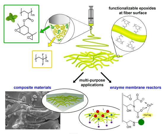
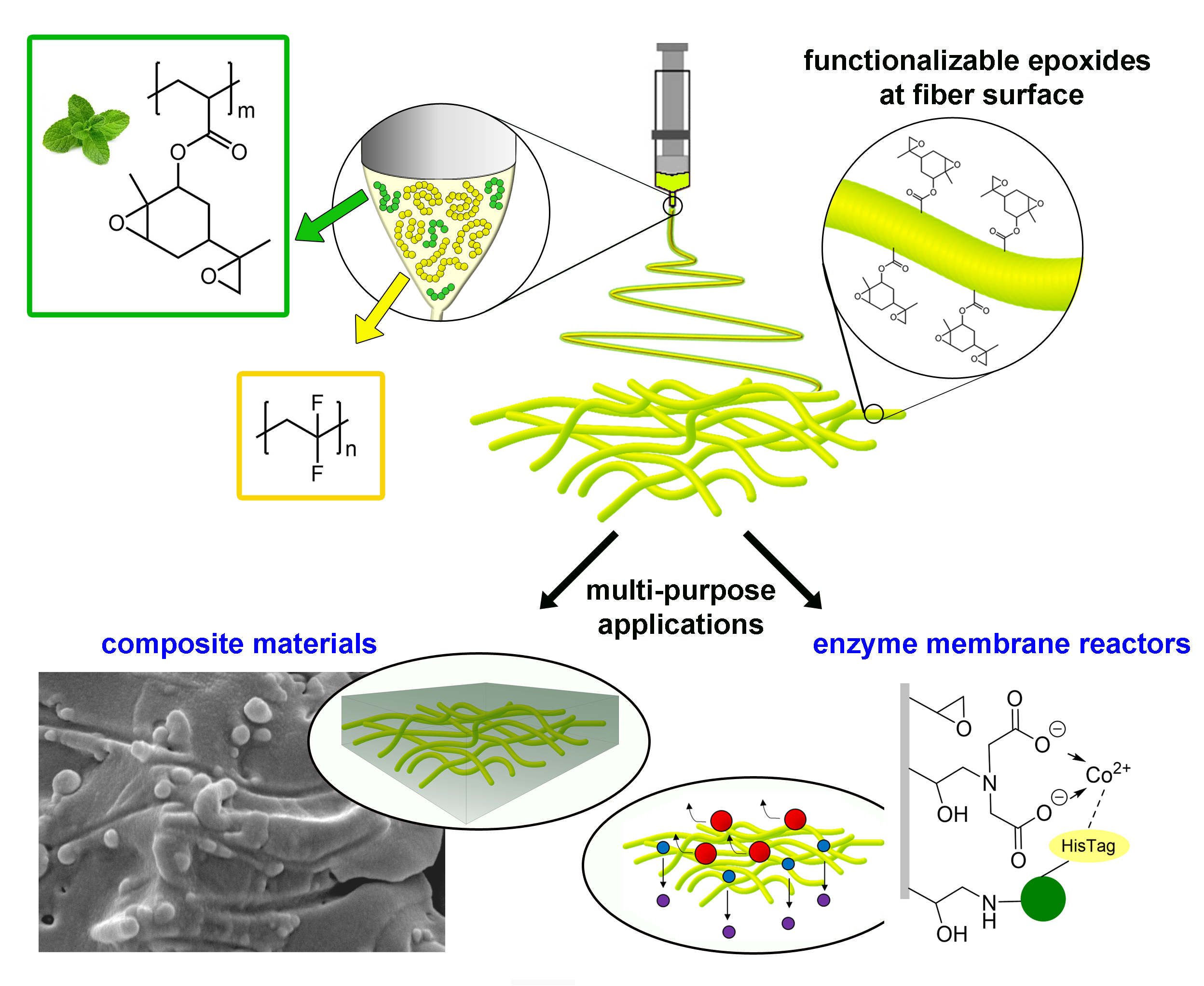
Functionalisable Epoxy-rich Electrospun Fibres Based on Renewable Terpene for Multi-Purpose Applications

 ,
,  , ,
, , 
 ,
, 
Abstract
1. Introduction
2. Materials and Methods
2.1. Fibre Production and Characterisation
2.1.1. Materials
2.1.2. Electrospinning
2.1.3. Characterisation Techniques
2.2. Carbon Fibre Composites
2.2.1. Materials
2.2.2. Epoxy Resin−Electrospun Nanofibres Composites
2.2.3. CFRP Nano-Interleaved Composite Laminate
2.2.4. Characterisation Techniques
2.3. Enzyme Immobilisation
2.3.1. Materials
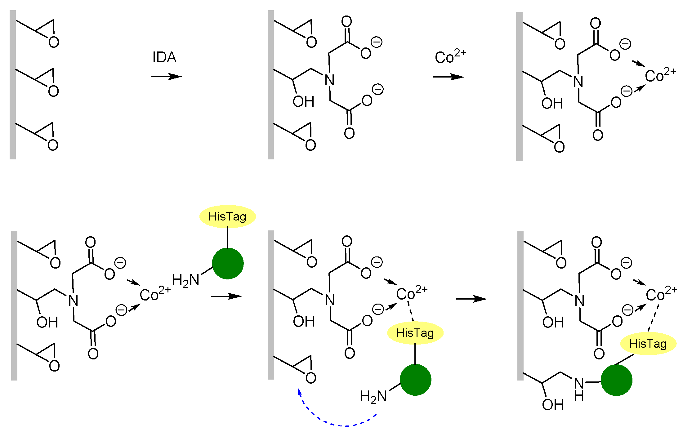
2.3.2. Immobilisation of HeWT on Metal-Derivatised PVDF/PCADE 70/30 Membranes
2.3.3. ω-Transaminase Activity Assay and Protein Determination
2.3.4. Recovered Activity Assay after Immobilisation on Membranes
3. Results
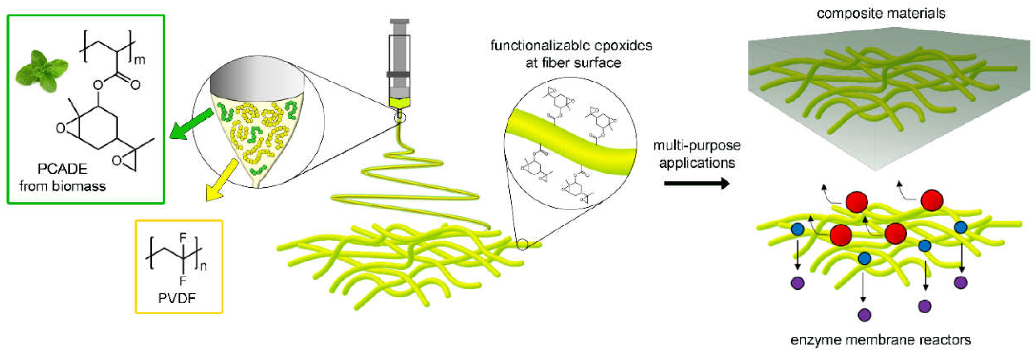
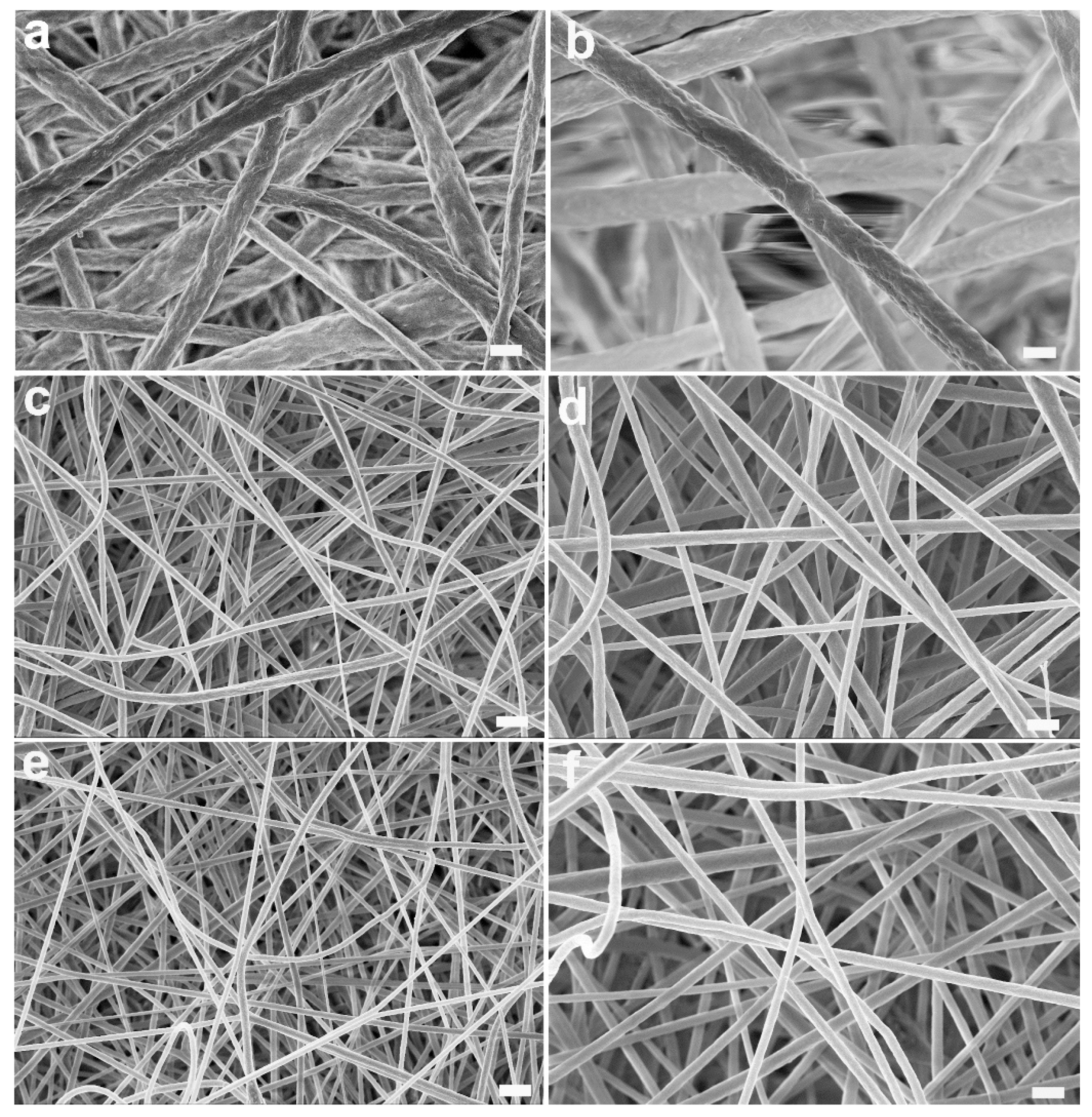
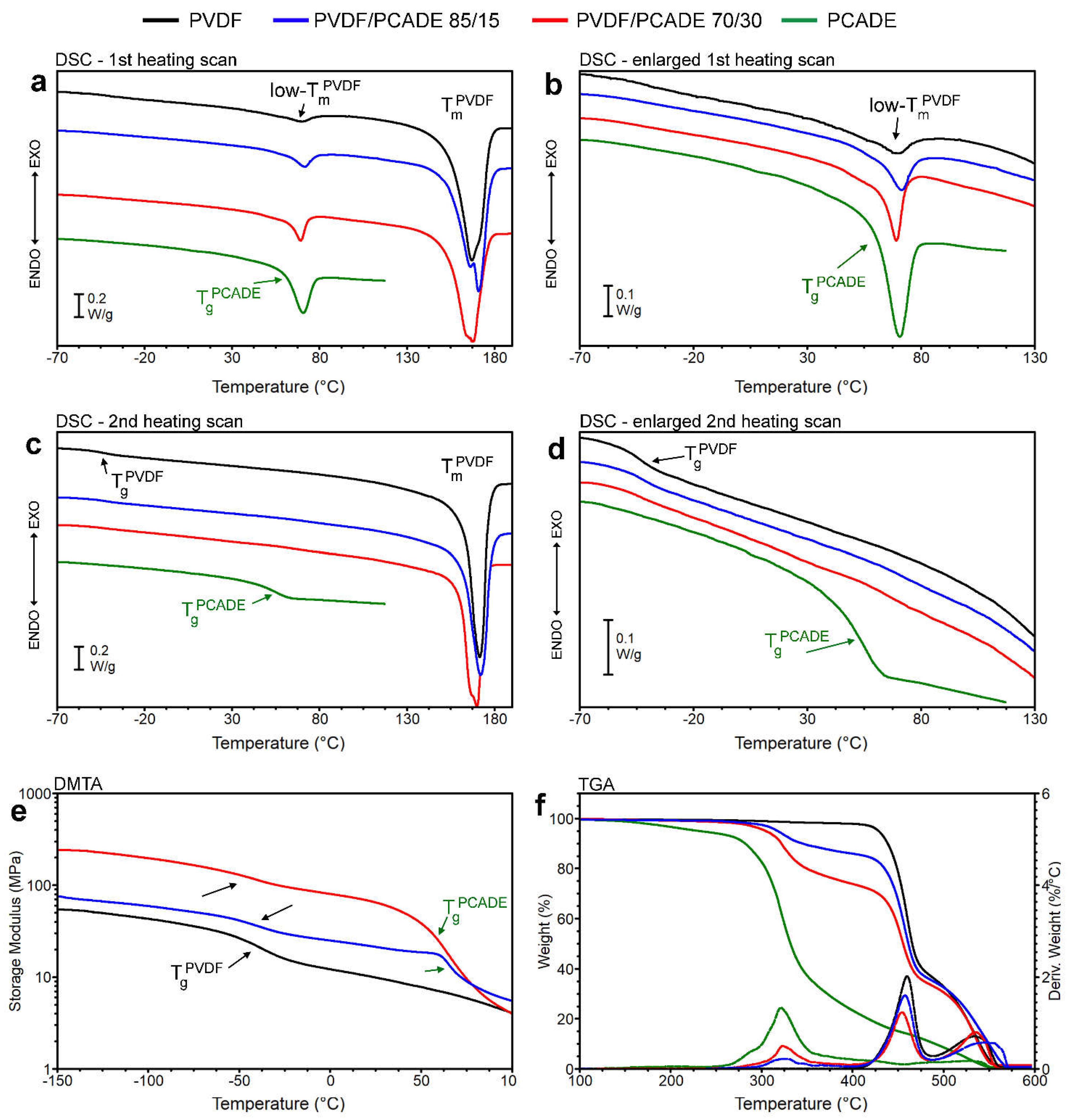
3.1. PVDF/PCADE Electrospun Samples
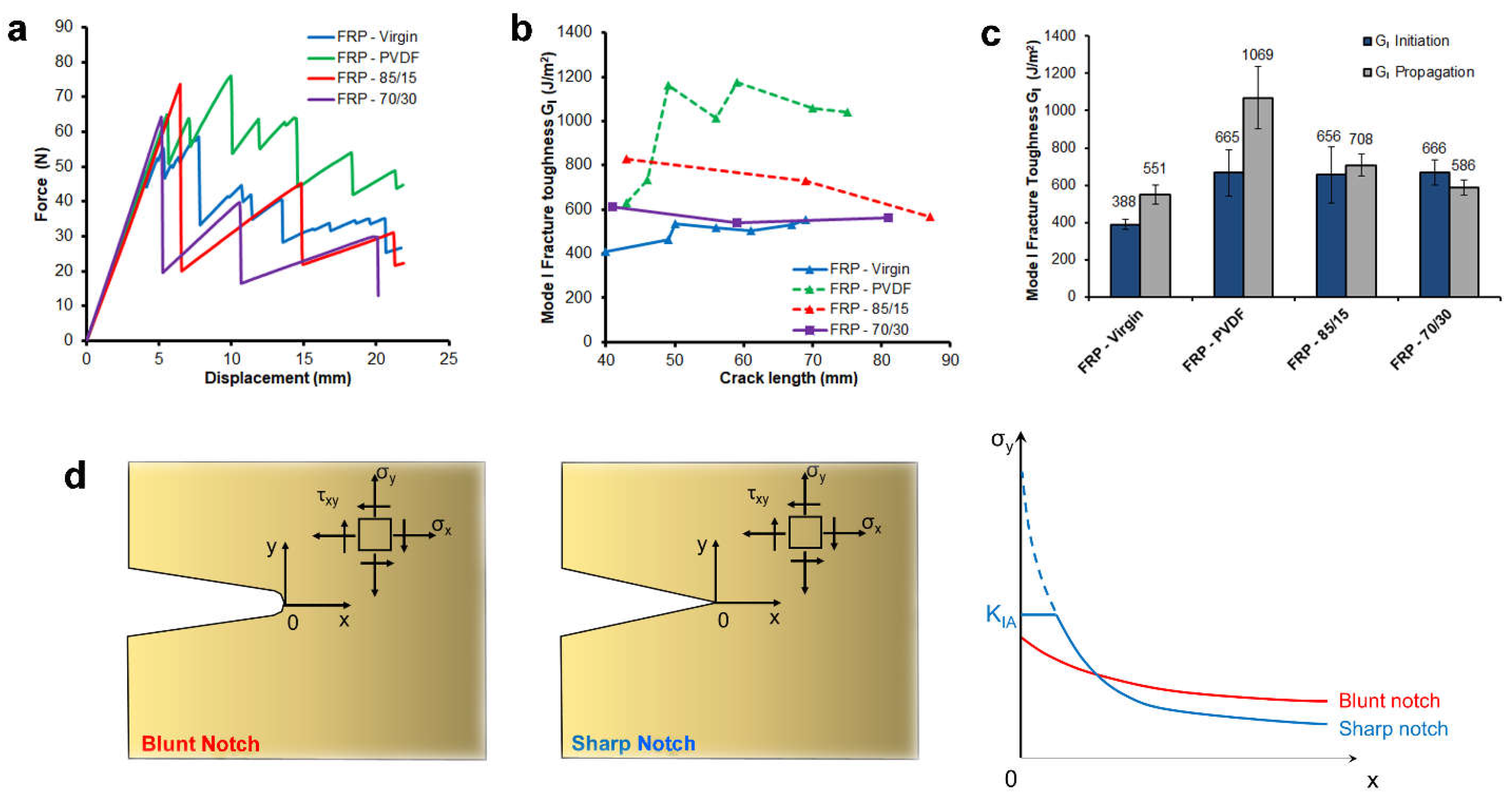
3.2. Epoxide-Based Composites
3.3. Enzyme Immobilisation
4. Conclusions
Supplementary Materials
Author Contributions
Funding
Acknowledgments
Conflicts of Interest
References
- Voros, V.; Drioli, E.; Fonte, C.P.; Szekely, G. Process Intensification via Continuous and Simultaneous Isolation of Antioxidants: An Upcycling Approach for Olive Leaf Waste. ACS Sustain. Chem. Eng. 2019, 7, 18444–18452. [Google Scholar] [CrossRef]
- Matassa, S.; Papirio, S.; Pikaar, I.; Hülsen, T.; Leijenhorst, E.; Esposito, G.; Pirozzi, F.; Verstraete, W. Upcycling of Biowaste Carbon and Nutrients in Line With Consumer Confidence: The “Full Gas” Route to Single Cell Protein. Green Chem. 2020, 22, 4912–4929. [Google Scholar] [CrossRef]
- Wang, Z.; Ganewatta, M.S.; Tang, C. Sustainable Polymers from Biomass: Bridging Chemistry with Materials and Processing. Prog. Polym. Sci. 2020, 101, 101197. [Google Scholar] [CrossRef]
- Brodin, M.; Vallejos, M.; Opedal, M.T.; Area, M.C.; Chinga-Carrasco, G. Lignocellulosics as Sustainable Resources for Production of Bioplastics—A Review. J. Clean. Prod. 2017, 162, 646–664. [Google Scholar] [CrossRef]
- Rodriguez-Perez, S.; Serrano, A.; Pantión, A.A.; Alonso-Fariñas, B. Challenges of Scaling-up PHA Production from Waste Streams. A Review. J. Environ. Manag. 2018, 205, 215–230. [Google Scholar] [CrossRef]
- Top 20 Innovative Bio-Based Products; Publications Office of the European Union: Brussels, Belgium, 2019; Available online: https://op.europa.eu/en/publication-detail/-/publication/15135e98-81c2-11e9-9f05-01aa75ed71a1 (accessed on 29 May 2021).
- Della Monica, F.; Kleij, A.W. From Terpenes to Sustainable and Functional Polymers. Polym. Chem. 2020, 11, 5109–5127. [Google Scholar] [CrossRef]
- Thomsett, M.R.; Moore, J.C.; Buchard, A.; Stockman, R.A.; Howdle, S.M. New Renewably-Sourced Polyesters from Limonene-Derived Monomers. Green Chem. 2019, 21, 149–156. [Google Scholar] [CrossRef]
- Winnacker, M.; Neumeier, M.; Zhang, X.; Papadakis, C.M.; Rieger, B. Sustainable Chiral Polyamides with High Melting Temperature via Enhanced Anionic Polymerization of a Menthone-Derived Lactam. Macromol. Rapid Commun. 2016, 37, 851–857. [Google Scholar] [CrossRef]
- Bähr, M.; Bitto, A.; Mülhaupt, R. Cyclic Limonene Dicarbonate as a New Monomer for Non-Isocyanate Oligo- and Polyurethanes (NIPU) Based upon Terpenes. Green Chem. 2012, 14, 1447–1454. [Google Scholar] [CrossRef]
- Hauenstein, O.; Agarwal, S.; Greiner, A. Bio-Based Polycarbonate as Synthetic Toolbox. Nat. Commun. 2016, 7, 11862. [Google Scholar] [CrossRef]
- Feder-Kubis, J.; Zabielska-Matejuk, J.; Stangierska, A.; Przybylski, P.; Jacquemin, J.; Geppert-Rybczyńska, M. Toward Designing “Sweet” Ionic Liquids Containing a Natural Terpene Moiety as Effective Wood Preservatives. ACS Sustain. Chem. Eng. 2019, 7, 15628–15639. [Google Scholar] [CrossRef]
- Park, S.-H.; Alammar, A.; Fulop, Z.; Pulido, B.A.; Nunes, S.P.; Szekely, G. Hydrophobic Thin Film Composite Nanofiltration Membranes Derived Solely from Sustainable Sources. Green Chem. 2021, 23, 1175–1184. [Google Scholar] [CrossRef]
- Pacuła, A.J.; Ścianowski, J. Terpenes as Green Starting Materials for New Organoselenium and Organotellurium Compounds. Curr. Green Chem. 2016, 3, 36–50. [Google Scholar]
- Montanari, U.; Taresco, V.; Liguori, A.; Gualandi, C.; Howdle, S.M. Synthesis of Novel Carvone (Meth)Acrylate Monomers for the Production of Hydrophilic Polymers with High Terpene Content. Polym. Int. 2021, 70, 499–505. [Google Scholar] [CrossRef]
- Gualandi, C.; Celli, A.; Zucchelli, A.; Focarete, M.L. Nanohybrid Materials by Electrospinning. In Organic-Inorganic Hybrid Nanomaterials; Kalia, S., Haldorai, Y., Eds.; Springer International Publishing: Cham, Switzerland, 2015; pp. 87–142. ISBN 9783319135939. [Google Scholar]
- Xue, J.; Wu, T.; Dai, Y.; Xia, Y. Electrospinning and Electrospun Nanofibers: Methods, Materials, and Applications. Chem. Rev. 2019, 119, 5298–5415. [Google Scholar] [CrossRef]
- Sagitha, P.; Reshmi, C.R.; Sundaran, S.P.; Sujith, A. Recent Advances in Post-Modification Strategies of Polymeric Electrospun Membranes. Eur. Polym. J. 2018, 105, 227–249. [Google Scholar] [CrossRef]
- Dolci, L.S.; Quiroga, S.D.; Gherardi, M.; Laurita, R.; Liguori, A.; Sanibondi, P.; Fiorani, A.; Calzà, L.; Colombo, V.; Focarete, M.L. Carboxyl Surface Functionalization of Poly(L-Lactic Acid) Electrospun Nanofibers through Atmospheric Non-Thermal Plasma Affects Fibroblast Morphology. Plasma Process. Polym. 2014, 11, 203–213. [Google Scholar] [CrossRef]
- Cheng, Q.; Lee, B.L.-P.; Komvopoulos, K.; Yan, Z.; Li, S. Plasma Surface Chemical Treatment of Electrospun Poly(L-Lactide) Microfibrous Scaffolds for Enhanced Cell Adhesion, Growth, and Infiltration. Tissue Eng. Part A 2013, 19, 1188–1198. [Google Scholar] [CrossRef] [PubMed]
- Qiu, X.; Lee, B.L.P.; Ning, X.; Murthy, N.; Dong, N.; Li, S. End-Point Immobilization of Heparin on Plasma-Treated Surface of Electrospun Polycarbonate-Urethane Vascular Graft. Acta Biomater. 2017, 51, 138–147. [Google Scholar] [CrossRef] [PubMed]
- Pagnotta, G.; Graziani, G.; Baldini, N.; Maso, A.; Focarete, M.L.; Berni, M.; Biscarini, F.; Bianchi, M.; Gualandi, C. Nanodecoration of Electrospun Polymeric Fibers with Nanostructured Silver Coatings by Ionized Jet Deposition for Antibacterial Tissues. Mater. Sci. Eng. C 2020, 113, 110998. [Google Scholar] [CrossRef]
- Santala, E.; Kemell, M.; Leskelä, M.; Ritala, M. The Preparation of Reusable Magnetic and Photocatalytic Composite Nanofibers by Electrospinning and Atomic Layer Deposition. Nanotechnology 2009, 20, 035602. [Google Scholar] [CrossRef] [PubMed]
- Gualandi, C.; Vo, C.D.; Focarete, M.L.; Scandola, M.; Pollicino, A.; Di Silvestro, G.; Tirelli, N. Advantages of Surface-Initiated ATRP (SI-ATRP) for the Functionalization of Electrospun Materials. Macromol. Rapid Commun. 2013, 34. [Google Scholar] [CrossRef]
- Chang, Z.; Xu, Y.; Zhao, X.; Zhang, Q.; Chen, D. Grafting Poly(Methyl Methacrylate) onto Polyimide Nanofibers via “Click” Reaction. ACS Appl. Mater. Interfaces 2009, 1, 2804–2811. [Google Scholar] [CrossRef] [PubMed]
- Feng, Q.; Hou, D.; Zhao, Y.; Xu, T.; Menkhaus, T.J.; Fong, H. Electrospun Regenerated Cellulose Nanofibrous Membranes Surface-Grafted with Polymer Chains/Brushes via the Atom Transfer Radical Polymerization Method for Catalase Immobilization. ACS Appl. Mater. Interfaces 2014, 6, 20958–20967. [Google Scholar] [CrossRef]
- Amokrane, G.; Humblot, V.; Jubeli, E.; Yagoubi, N.; Ramtani, S.; Migonney, V.; Falentin-Daudré, C. Electrospun Poly(ε-Caprolactone) Fiber Scaffolds Functionalized by the Covalent Grafting of a Bioactive Polymer: Surface Characterization and Influence on in Vitro Biological Response. ACS Omega 2019, 4, 17194–17208. [Google Scholar] [CrossRef] [PubMed]
- Ghasemi-Mobarakeh, L.; Prabhakaran, M.P.; Morshed, M.; Nasr-Esfahani, M.H.; Ramakrishna, S. Bio-Functionalized PCL Nanofibrous Scaffolds for Nerve Tissue Engineering. Mater. Sci. Eng. C 2010, 30, 1129–1136. [Google Scholar] [CrossRef]
- Sun, X.-Y.; Shankar, R.; Börner, H.G.; Ghosh, T.K.; Spontak, R.J. Field-Driven Biofunctionalization of Polymer Fiber Surfaces during Electrospinning. Adv. Mater. 2007, 19, 87–91. [Google Scholar] [CrossRef]
- Gentsch, R.; Pippig, F.; Schmidt, S.; Cernoch, P.; Polleux, J.; Börner, H.G. Single-Step Electrospinning to Bioactive Polymer Nanofibers. Macromolecules 2011, 44, 453–461. [Google Scholar] [CrossRef]
- Maccaferri, E.; Mazzocchetti, L.; Benelli, T.; Zucchelli, A.; Giorgini, L. Morphology, Thermal, Mechanical Properties and Ageing of Nylon 6,6/Graphene Nanofibers as Nano2 Materials. Compos. Part B Eng. 2019, 166, 120–129. [Google Scholar] [CrossRef]
- Brugo, T.M.; Minak, G.; Zucchelli, A.; Saghafi, H.; Fotouhi, M. An Investigation on the Fatigue Based Delamination of Woven Carbon-Epoxy Composite Laminates Reinforced with Polyamide Nanofibers. Procedia Eng. 2015, 109, 65–72. [Google Scholar] [CrossRef]
- ASTM D5528 Standard Test Method for Mode I Interlaminar Fracture Toughness of Unidirectional Fiber-Reinforced Polymer Matrix Composites; ASTM International: West Conshohocken, PA, USA, 2009.
- Cerioli, L.; Planchestainer, M.; Cassidy, J.; Tessaro, D.; Paradisi, F. Characterization of a Novel Amine Transaminase from Halomonas Elongata. J. Mol. Catal. B Enzym. 2015, 120, 141–150. [Google Scholar] [CrossRef]
- Mateo, C.; Fernández-Lorente, G.; Cortés, E.; Garcia, J.L.; Fernández-Lafuente, R.; Guisan, J.M. One-Step Purification, Covalent Immobilization, and Additional Stabilization of Poly-His-Tagged Proteins Using Novel Heterofunctional Chelate-Epoxy Supports. Biotechnol. Bioeng. 2001, 76, 269–276. [Google Scholar] [CrossRef]
- McKee, M.G.; Wilkes, G.L.; Colby, R.H.; Long, T.E. Correlations of Solution Rheology with Electrospun Fiber Formation of Linear and Branched Polyesters. Macromolecules 2004, 37, 1760–1767. [Google Scholar] [CrossRef]
- Shenoy, S.L.; Bates, W.D.; Frisch, H.L.; Wnek, G.E. Role of Chain Entanglements on Fiber Formation during Electrospinning of Polymer Solutions: Good Solvent, Non-Specific Polymer-Polymer Interaction Limit. Polymer 2005, 46, 3372–3384. [Google Scholar] [CrossRef]
- Liu, F.; Hashim, N.A.; Liu, Y.; Abed, M.R.M.; Li, K. Progress in the Production and Modification of PVDF Membranes. J. Memb. Sci. 2011, 375, 1–27. [Google Scholar] [CrossRef]
- Kang, G.D.; Cao, Y.M. Application and Modification of Poly(Vinylidene Fluoride) (PVDF) Membranes—A Review. J. Memb. Sci. 2014, 463, 145–165. [Google Scholar] [CrossRef]
- Ji, J.; Liu, F.; Hashim, N.A.; Abed, M.R.M.; Li, K. Poly(Vinylidene Fluoride) (PVDF) Membranes for Fluid Separation. React. Funct. Polym. 2015, 86, 134–153. [Google Scholar] [CrossRef]
- Soulestin, T.; Ladmiral, V.; Dos Santos, F.D.; Améduri, B. Vinylidene Fluoride- and Trifluoroethylene-Containing Fluorinated Electroactive Copolymers. How Does Chemistry Impact Properties? Prog. Polym. Sci. 2017, 72, 16–60. [Google Scholar] [CrossRef]
- Chen, X.; Han, X.; Shen, Q.-D. PVDF-Based Ferroelectric Polymers in Modern Flexible Electronics. Adv. Electron. Mater. 2017, 3, 1600460. [Google Scholar] [CrossRef]
- Totaro, G.; Paltrinieri, L.; Mazzola, G.; Vannini, M.; Sisti, L.; Gualandi, C.; Ballestrazzi, A.; Valeri, S.; Pollicino, A.; Celli, A.; et al. Electrospun Fibers Containing Bio-Based Ricinoleic Acid: Effect of Amount and Distribution of Ricinoleic Acid Unit on Antibacterial Properties. Macromol. Mater. Eng. 2015, 300. [Google Scholar] [CrossRef]
- Hunley, M.T.; Harber, A.; Orlicki, J.A.; Rawlett, A.M.; Long, T.E. Effect of Hyperbranched Surface-Migrating Additives on the Electrospinning Behavior of Poly(Methyl Methacrylate). Langmuir 2008, 24, 654–657. [Google Scholar] [CrossRef]
- Hardman, S.J.; Muhamad-Sarih, N.; Riggs, H.J.; Thompson, R.L.; Rigby, J.; Bergius, W.N.A.; Hutchings, L.R. Electrospinning Superhydrophobic Fibers Using Surface Segregating End-Functionalized Polymer Additives. Macromolecules 2011, 44, 6461–6470. [Google Scholar] [CrossRef]
- Neidhöfer, M.; Beaume, F.; Ibos, L.; Bernès, A.; Lacabanne, C. Structural Evolution of PVDF during Storage or Annealing. Polymer 2004, 45, 1679–1688. [Google Scholar] [CrossRef]
- Gupta, N. Metal and Polymer Matrix Composites II. JOM 2016, 68, 1858–1860. [Google Scholar] [CrossRef]
- Abdellaoui, H.; Raji, M.; Bouhfid, R.; El Kacem, Q.A. Investigation of the deformation behavior of epoxy-based composite materials. In Failure Analysis in Biocomposites, Fibre-Reinforced Composites and Hybrid Composites; Elsevier: Amsterdam, The Netherlands, 2018; pp. 29–49. ISBN 9780081022931. [Google Scholar]
- Palazzetti, R.; Zucchelli, A. Electrospun Nanofibers as Reinforcement for Composite Laminates Materials—A Review. Compos. Struct. 2017, 182, 711–727. [Google Scholar] [CrossRef]
- Zucchelli, A.; Focarete, M.L.; Gualandi, C.; Ramakrishna, S. Electrospun Nanofibers for Enhancing Structural Performance of Composite Materials. Polym. Adv. Technol. 2011, 22, 339–349. [Google Scholar] [CrossRef]
- Wang, G.; Yu, D.; Kelkar, A.D.; Zhang, L. Electrospun Nanofiber: Emerging Reinforcing Filler in Polymer Matrix Composite Materials. Prog. Polym. Sci. 2017, 75, 73–107. [Google Scholar] [CrossRef]
- Alessi, S.; Di Filippo, M.; Dispenza, C.; Focarete, M.L.; Gualandi, C.; Palazzetti, R.; Pitarresi, G.; Zucchelli, A. Effects of Nylon 6,6 Nanofibrous Mats on Thermal Properties and Delamination Behavior of High Performance CFRP Laminates. Polym. Compos. 2014, 36, 1303–1313. [Google Scholar] [CrossRef]
- Palazzetti, R.; Zucchelli, A.; Gualandi, C.; Focarete, M.L.; Donati, L.; Minak, G.; Ramakrishna, S. Influence of Electrospun Nylon 6,6 Nanofibrous Mats on the Interlaminar Properties of Gr-Epoxy Composite Laminates. Compos. Struct. 2012, 94, 571–579. [Google Scholar] [CrossRef]
- Brugo, T.; Minak, G.; Zucchelli, A.; Yan, X.T.; Belcari, J.; Saghafi, H.; Palazzetti, R. Study on Mode I Fatigue Behaviour of Nylon 6,6 Nanoreinforced CFRP Laminates. Compos. Struct. 2017, 164, 51–57. [Google Scholar] [CrossRef]
- Saghafi, H.; Brugo, T.; Minak, G.; Zucchelli, A. The Effect of PVDF Nanofibers on Mode-I Fracture Toughness of Composite Materials. Compos. Part B Eng. 2015, 72, 213–216. [Google Scholar] [CrossRef]
- Quaresimin, M.; Schulte, K.; Zappalorto, M.; Chandrasekaran, S. Toughening Mechanisms in Polymer Nanocomposites: From Experiments to Modelling. Compos. Sci. Technol. 2016, 123, 187–204. [Google Scholar] [CrossRef]
- Hsieh, T.H.; Kinloch, A.J.; Masania, K.; Taylor, A.C.; Sprenger, S. The Mechanisms and Mechanics of the Toughening of Epoxy Polymers Modified with Silica Nanoparticles. Polymer 2010, 51, 6284–6294. [Google Scholar] [CrossRef]
- Zappalorto, M.; Salviato, M.; Quaresimin, M. A Multiscale Model to Describe Nanocomposite Fracture Toughness Enhancement by the Plastic Yielding of Nanovoids. Compos. Sci. Technol. 2012, 72, 1683–1691. [Google Scholar] [CrossRef]
- Wang, X.; Jin, J.; Song, M. An Investigation of the Mechanism of Graphene Toughening Epoxy. Carbon N. Y. 2013, 65, 324–333. [Google Scholar] [CrossRef]
- Salviato, M.; Zappalorto, M.; Quaresimin, M. Plastic Shear Bands and Fracture Toughness Improvements of Nanoparticle Filled Polymers: A Multiscale Analytical Model. Compos. Part A Appl. Sci. Manuf. 2013, 48, 144–152. [Google Scholar] [CrossRef]
- Allaoui, A.; Bai, S.; Cheng, H.M.; Bai, J.B. Mechanical and Electrical Properties of a MWNT/Epoxy Composite. Compos. Sci. Technol. 2002, 62, 1993–1998. [Google Scholar] [CrossRef]
- Chandrasekaran, S.; Sato, N.; Tölle, F.; Mülhaupt, R.; Fiedler, B.; Schulte, K. Fracture Toughness and Failure Mechanism of Graphene Based Epoxy Composites. Compos. Sci. Technol. 2014, 97, 90–99. [Google Scholar] [CrossRef]
- Liu, T.; Tjiu, W.C.; Tong, Y.; He, C.; Goh, S.S.; Chung, T.-S. Morphology and Fracture Behavior of Intercalated Epoxy/Clay Nanocomposites. J. Appl. Polym. Sci. 2004, 94, 1236–1244. [Google Scholar] [CrossRef]
- Wang, K.; Chen, L.; Wu, J.; Toh, M.L.; He, C.; Yee, A.F. Epoxy Nanocomposites with Highly Exfoliated Clay: Mechanical Properties and Fracture Mechanisms. Macromolecules 2005, 38, 788–800. [Google Scholar] [CrossRef]
- Lange, F.F. The Interaction of a Crack Front with a Second-Phase Dispersion. Philos. Mag. 1970, 22, 983–992. [Google Scholar] [CrossRef]
- Özden, E.; Menceloğlu, Y.Z.; Papila, M. Engineering Chemistry of Electrospun Nanofibers and Interfaces in Nanocomposites for Superior Mechanical Properties. ACS Appl. Mater. Interfaces 2010, 2, 1788–1793. [Google Scholar] [CrossRef] [PubMed]
- Neisiany, R.E.; Khorasani, S.N.; Naeimirad, M.; Lee, J.K.Y.; Ramakrishna, S. Improving Mechanical Properties of Carbon/Epoxy Composite by Incorporating Functionalized Electrospun Polyacrylonitrile Nanofibers. Macromol. Mater. Eng. 2017, 302, 1600551. [Google Scholar] [CrossRef]
- Özden-Yenigün, E.; Menceloğlu, Y.Z.; Papila, M. MWCNTs/P(St-Co-GMA) Composite Nanofibers of Engineered Interface Chemistry for Epoxy Matrix Nanocomposites. ACS Appl. Mater. Interfaces 2012, 4, 777–784. [Google Scholar] [CrossRef]
- Anderson, T.L.; Anderson, T.L. Fracture Mechanics: Fundamentals and Applications, 3rd ed.; CRC Press: Boca Raton, FL, USA, 2005. [Google Scholar]
- Cen, Y.-K.; Liu, Y.-X.; Xue, Y.-P.; Zheng, Y.-G. Immobilization of Enzymes in/on Membranes and Their Applications. Adv. Synth. Catal. 2019, 361, 5500–5515. [Google Scholar] [CrossRef]
- Liu, X.; Fang, Y.; Yang, X.; Li, Y.; Wang, C. Electrospun Nanofibrous Membranes Containing Epoxy Groups and Hydrophilic Polyethylene Oxide Chain for Highly Active and Stable Covalent Immobilization of Lipase. Chem. Eng. J. 2018, 336, 456–464. [Google Scholar] [CrossRef]
- Wang, D.; Sun, G.; Xiang, B.; Chiou, B. Sen Controllable Biotinylated Poly(Ethylene-Co-Glycidyl Methacrylate) (PE-Co-GMA) Nanofibers to Bind Streptavidin-Horseradish Peroxidase (HRP) for Potential Biosensor Applications. Eur. Polym. J. 2008, 44, 2032–2039. [Google Scholar] [CrossRef]
- Ye, P.; Xu, Z.K.; Wu, J.; Innocent, C.; Seta, P. Nanofibrous Poly(Acrylonitrile-Co-Maleic Acid) Membranes Functionalized with Gelatin and Chitosan for Lipase Immobilization. Biomaterials 2006, 27, 4169–4176. [Google Scholar] [CrossRef]
- Planchestainer, M.; Contente, M.L.; Cassidy, J.; Molinari, F.; Tamborini, L.; Paradisi, F. Continuous Flow Biocatalysis: Production and in-Line Purification of Amines by Immobilised Transaminase from Halomonas Elongata. Green Chem. 2017, 19, 372–375. [Google Scholar] [CrossRef]
- Contente, M.L.; Paradisi, F. Self-Sustaining Closed-Loop Multienzyme-Mediated Conversion of Amines into Alcohols in Continuous Reactions. Nat. Catal. 2018, 1, 452–459. [Google Scholar] [CrossRef]


| Electrospun Samples | Total PVDF/PCADE 1 (wt/wt) | F/C | O/C | F/O | Surface PVDF/PCADE 2 (wt/wt) | |
|---|---|---|---|---|---|---|
| PVDF/PCADE 85/15 | 85/15 | Theoretical 3 | 0.77 | 0.071 | 10.9 | 67/33 |
| Experimental 4 | 0.55 | 0.14 | 3.90 | |||
| PVDF/PCADE 70/30 | 70/30 | Theoretical 3 | 0.58 | 0.13 | 4.5 | 47/53 |
| Experimental 4 | 0.32 | 0.19 | 1.7 |
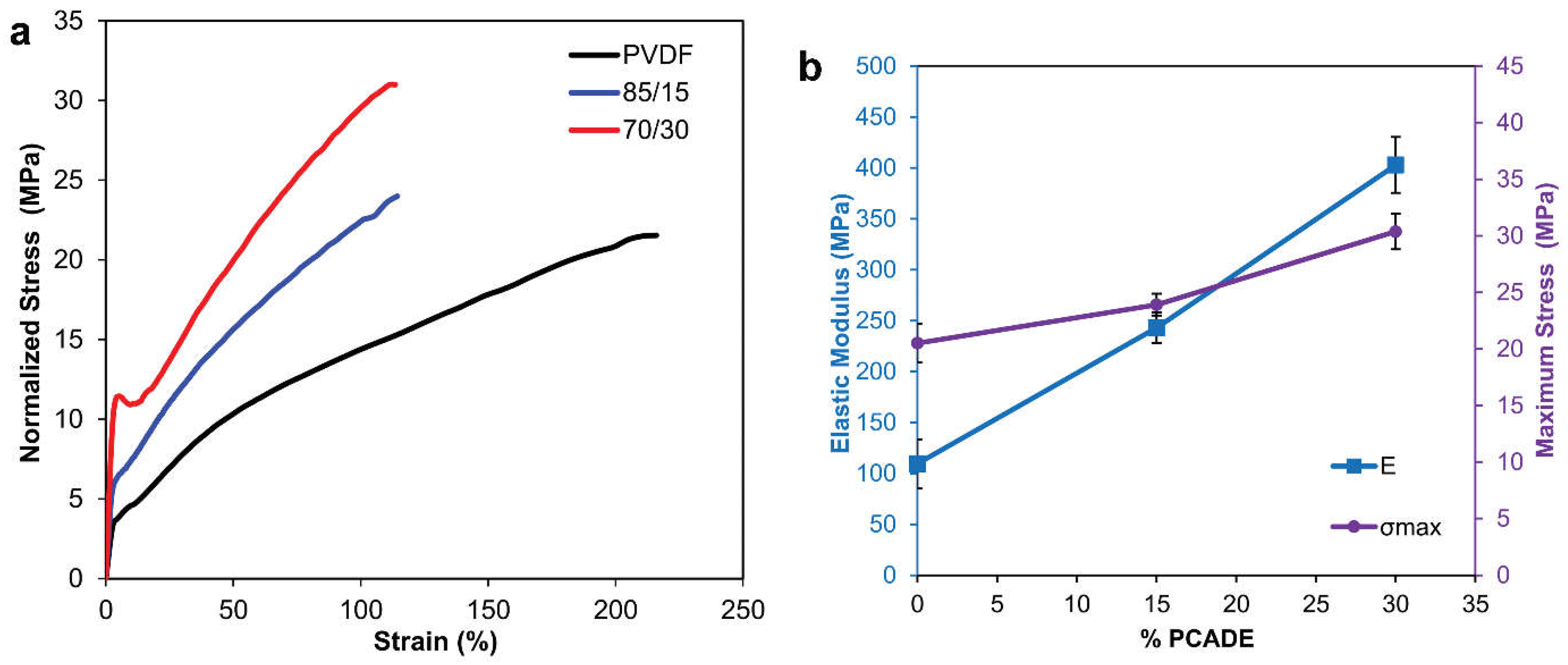
| Electrospun Sample | E(MPa) | σmax (MPa) | εmax (%) | U (J/cm3) |
|---|---|---|---|---|
| PVDF | 109 ± 24 | 20.5 ± 1.7 | 238 ± 18 | 32.0 ± 4.4 |
| PVDF/PCADE 85/15 | 243 ± 15 | 23.9 ± 1 | 117 ± 8 | 19.0 ± 1.5 |
| PVDF/PCADE 70/30 | 403 ± 28 | 30.4 ± 1.6 | 117 ± 11 | 23.9 ± 2.9 |
| Immobilisation Parameter | Co2+-2hIDA Membrane | Co2+-102hIDA Membrane |
|---|---|---|
| Offered enzyme (mg gmembrane−1) | 10 | 10 |
| Immobilised activity (U gmembrane−1) 1 | 10.7 | 27.2 |
| Immobilisation yield(%) 1 | 24.4 | 61.9 |
| Recovered activity (U gmembrane−1) 1 | 2.9 | 11.8 |
| Recovered activity (%)1 | 26.7 | 43.6 |
Publisher’s Note: MDPI stays neutral with regard to jurisdictional claims in published maps and institutional affiliations. |
© 2021 by the authors. Licensee MDPI, Basel, Switzerland. This article is an open access article distributed under the terms and conditions of the Creative Commons Attribution (CC BY) license (https://creativecommons.org/licenses/by/4.0/).
Share and Cite
Montanari, U.; Cocchi, D.; Brugo, T.M.; Pollicino, A.; Taresco, V.; Romero Fernandez, M.; Moore, J.C.; Sagnelli, D.; Paradisi, F.; Zucchelli, A.; et al. Functionalisable Epoxy-rich Electrospun Fibres Based on Renewable Terpene for Multi-Purpose Applications. Polymers 2021, 13, 1804. https://doi.org/10.3390/polym13111804
Montanari U, Cocchi D, Brugo TM, Pollicino A, Taresco V, Romero Fernandez M, Moore JC, Sagnelli D, Paradisi F, Zucchelli A, et al. Functionalisable Epoxy-rich Electrospun Fibres Based on Renewable Terpene for Multi-Purpose Applications. Polymers. 2021; 13(11):1804. https://doi.org/10.3390/polym13111804
Chicago/Turabian StyleMontanari, Ulisse, Davide Cocchi, Tommaso Maria Brugo, Antonino Pollicino, Vincenzo Taresco, Maria Romero Fernandez, Jonathan C. Moore, Domenico Sagnelli, Francesca Paradisi, Andrea Zucchelli, and et al. 2021. "Functionalisable Epoxy-rich Electrospun Fibres Based on Renewable Terpene for Multi-Purpose Applications" Polymers 13, no. 11: 1804. https://doi.org/10.3390/polym13111804
APA StyleMontanari, U., Cocchi, D., Brugo, T. M., Pollicino, A., Taresco, V., Romero Fernandez, M., Moore, J. C., Sagnelli, D., Paradisi, F., Zucchelli, A., Howdle, S. M., & Gualandi, C. (2021). Functionalisable Epoxy-rich Electrospun Fibres Based on Renewable Terpene for Multi-Purpose Applications. Polymers, 13(11), 1804. https://doi.org/10.3390/polym13111804