Automated Polymer Purification Using Dialysis


Abstract

1. Introduction
2. Materials and Methods
2.1. Materials and Methods
2.2. Synthesis of the Polymers
2.2.1. Reversible Addition-Fragmentation Chain Transfer (RAFT) Polymerization of Methyl Methacrylate (P1–P2)
2.2.2. Free Radical Polymerization of Styrene (P3)
2.3. Dialysis
2.3.1. Manual Dialysis (Experiments M1–M3)
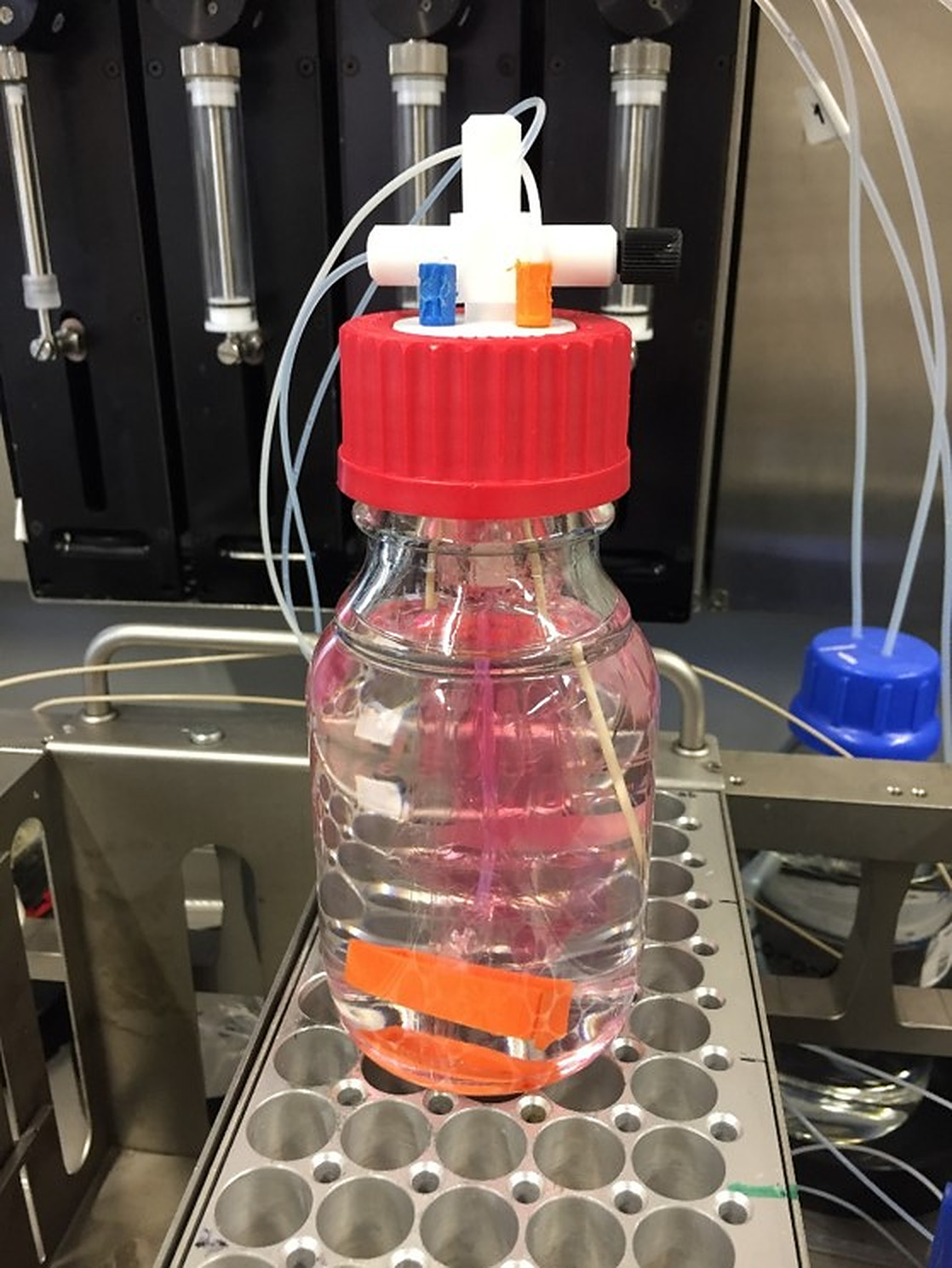
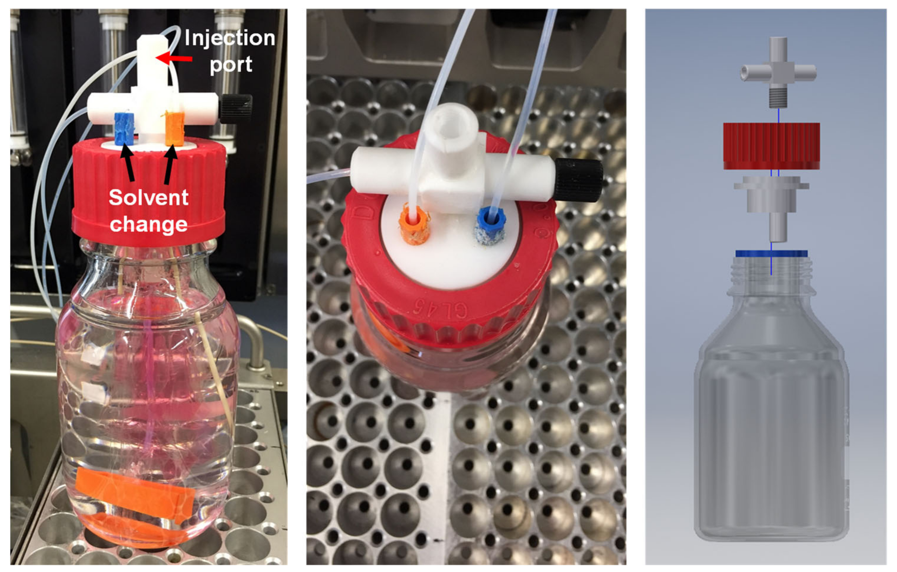
2.3.2. Automated Dialysis (Experiments A1–A4)
2.3.3. Video Automated Dialysis
3. Results and Discussion
4. Conclusions
Supplementary Materials
Author Contributions
Funding
Conflicts of Interest
References
- Almeida, A.F.; Moreira, R.; Rodrigues, T. Synthetic organic chemistry driven by artificial intelligence. Nat. Rev. Chem. 2019, 3, 589–604. [Google Scholar] [CrossRef]
- Milo, A. Democratizing synthesis by automation. Science 2019, 363, 122–123. [Google Scholar] [CrossRef]
- Rosenfeld, A.; Levkin, P.A. High--Throughput Combinatorial Synthesis of Stimuli--Responsive Materials. Adv. Biosyst. 2019, 3, 1800293. [Google Scholar] [CrossRef]
- Kumar, J.N.; Li, Q.; Jun, Y. Challenges and opportunities of polymer design with machine learning and high throughput experimentation. MRS Commun. 2019, 9, 537–544. [Google Scholar] [CrossRef]
- Coley, C.W.; Thomas, D.A.; Lummiss, J.A.M.; Jaworski, J.N.; Breen, C.P.; Schultz, V.; Hart, T.; Fishman, J.S.; Rogers, L.; Gao, H.; et al. A robotic platform for flow synthesis of organic compounds informed by AI planning. Science 2019, 365, eaax1566. [Google Scholar] [CrossRef] [PubMed]
- Geyer, K.; Codée, J.D.C.; Seeberger, P.H. Microreactors as Tools for Synthetic Chemists—The Chemists’ Round-Bottomed Flask of the 21st Century? Chem. A Eur. J. 2006, 12, 8434–8442. [Google Scholar] [CrossRef]
- Elvira, K.S.; I Solvas, X.C.; Wootton, R.C.R.; Demello, A.J. The past, present and potential for microfluidic reactor technology in chemical synthesis. Nat. Chem. 2013, 5, 905–915. [Google Scholar] [CrossRef]
- Chatterjee, S.; Guidi, M.; Seeberger, P.H.; Gilmore, K. Automated radial synthesis of organic molecules. Nature 2020, 579, 379–384. [Google Scholar] [CrossRef]
- Sletten, E.T.; Nuño, M.; Guthrie, D.; Seeberger, P.H. Real-time monitoring of solid-phase peptide synthesis using a variable bed flow reactor. Chem. Commun. 2019, 55, 14598–14601. [Google Scholar] [CrossRef]
- Ley, S.V.; Fitzpatrick, D.E.; Ingham, R.J.; Myers, R.M. Organic Synthesis: March of the Machines. Angew. Chem. Int. Ed. 2015, 54, 3449–3464. [Google Scholar] [CrossRef]
- Oliver, S.; Zhao, L.; Gormley, A.J.; Chapman, R.; Boyer, C. Living in the Fast Lane—High Throughput Controlled/Living Radical Polymerization. Macromolecules 2018, 52, 3–23. [Google Scholar] [CrossRef]
- Guerrero-Sanchez, C.; Harrisson, S.; Keddie, D.J. High-Throughput Method for RAFT Kinetic Investigations and Estimation of Reactivity Ratios in Copolymerization Systems. Macromol. Symp. 2013, 325, 38–46. [Google Scholar] [CrossRef]
- Yañez-Macías, R.; Kulai, I.; Ulbrich, J.; Yildirim, T.; Sungur, P.; Hoeppener, S.; Guerrero-Santos, R.; Schubert, U.S.; Destarac, M.; Guerrero-Sanchez, C.; et al. Thermosensitive spontaneous gradient copolymers with block- and gradient-like features. Polym. Chem. 2017, 8, 5023–5032. [Google Scholar] [CrossRef]
- Zhang, H.; Marin, V.; Fijten, M.W.M.; Schubert, U.S. High-throughput experimentation in atom transfer radical polymerization: A general approach toward a directed design and understanding of optimal catalytic systems. J. Polym. Sci. Part A Polym. Chem. 2004, 42, 1876–1885. [Google Scholar] [CrossRef]
- Voorhaar, L.; Hoogenboom, R. One-Pot Synthesis of Charged Amphiphilic Diblock and Triblock Copolymers Via High-Throughput Cu(0)-Mediated Polymerization. Polymers 2017, 9, 320. [Google Scholar] [CrossRef]
- Tamasi, M.; Kosuri, S.; Distefano, J.; Chapman, R.; Gormley, A.J. Automation of Controlled/Living Radical Polymerization. Adv. Intell. Syst. 2020, 2. [Google Scholar] [CrossRef]
- Eggenhuisen, T.M.; Becer, C.R.; Fijten, M.W.M.; Eckardt, R.; Hoogenboom, R.; Schubert, U.S. Libraries of Statistical Hydroxypropyl Acrylate Containing Copolymers with LCST Properties Prepared by NMP. Macromolecules 2008, 41, 5132–5140. [Google Scholar] [CrossRef]
- Upadhya, R.; Kanagala, M.J.; Gormley, A.J. Purifying Low--Volume Combinatorial Polymer Libraries with Gel Filtration Columns. Macromol. Rapid Commun. 2019, 40, 1900528. [Google Scholar] [CrossRef]
- Zhang, H.; Abeln, C.H.; Fijten, M.W.M.; Schubert, U.S. High-throughput experimentation applied to atom transfer radical polymerization: Automated optimization of the copper catalysts removal from polymers. e-Polymers 2006, 6. [Google Scholar] [CrossRef]
- Hoogenboom, R.; Fijten, M.W.M.; Meier, M.A.R.; Schubert, U.S. Living Cationic Polymerizations Utilizing an Automated Synthesizer: High-Throughput Synthesis of Polyoxazolines. Macromol. Rapid Commun. 2003, 24, 92–97. [Google Scholar] [CrossRef]
- Neufeld, C.H.H.; Marvel, C.S. The use of dialysis in polymer purification. J. Polym. Sci. Part A-1 Polym. Chem. 1966, 4, 2907–2908. [Google Scholar] [CrossRef]
- Aoki, M.; Matsuda, T.; Tomo, Y.; Miyata, Y.; Inoue, M.; Kigawa, T.; Yokoyama, S. Automated system for high-throughput protein production using the dialysis cell-free method. Protein Expr. Purif. 2009, 68, 128–136. [Google Scholar] [CrossRef] [PubMed]
- Wong, S.Y.; Chan, T.; Putnam, D. Simple and Economical High-Throughput Equilibrium Dialysis System. J. Comb. Chem. 2009, 11, 202–205. [Google Scholar] [CrossRef] [PubMed]


| Polymer | m(Monomer) (g) | V(DMF) (mL) | m(CTA) (mg) | m(AIBN) (mg) |
|---|---|---|---|---|
| P1 | 50 | 250 | 736.91 | 136.68 |
| P2 | 15 | 75 | 221.07 | 41.00 |
| Polymer | Mn (g/mol) | Mw (g/mol) | Ɖ |
|---|---|---|---|
| P1 | 6800 | 7800 | 1.14 |
| P2 | 12,600 | 14,300 | 1.13 |
| P3 | 42,300 | 64,000 | 1.51 |
| Experiment | Modus Operandi | Polymer | Additive | Solvent Change |
|---|---|---|---|---|
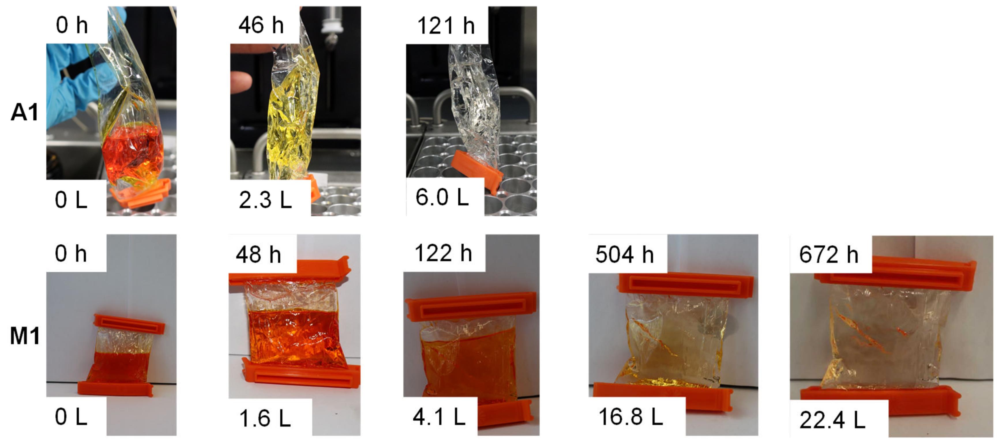
| M1 | Manual | P3 (500 mg) | Sudan 1 (10.1 mg) | 400 mL after 12 h; 55× in total |
| M2 | Manual | P1 (625 mg) | MMA (625 mg) | 400 mL after 12 h; 2× in total |
| M3 | Manual | P2 (15 mL solution) | – | 400 mL after 12 h; 2× in total |
| A1 | Automated (modus 1) | P3 (500 mg) | Sudan 1 (10.1 mg) | 50 mL/h; 121 h |
| A2 | Automated (modus 1) | P1 (625 mg) | MMA (625 mg) | 35 mL/h; 32 h |
| A3 | Automated (modus 1) | P2 (15 mL solution) | – | 35 mL/h; 32 h |
| A4 | Automated (modus 2) | P2 (15 mL solution) | – | 250 mL after 3 h; 5× in total |
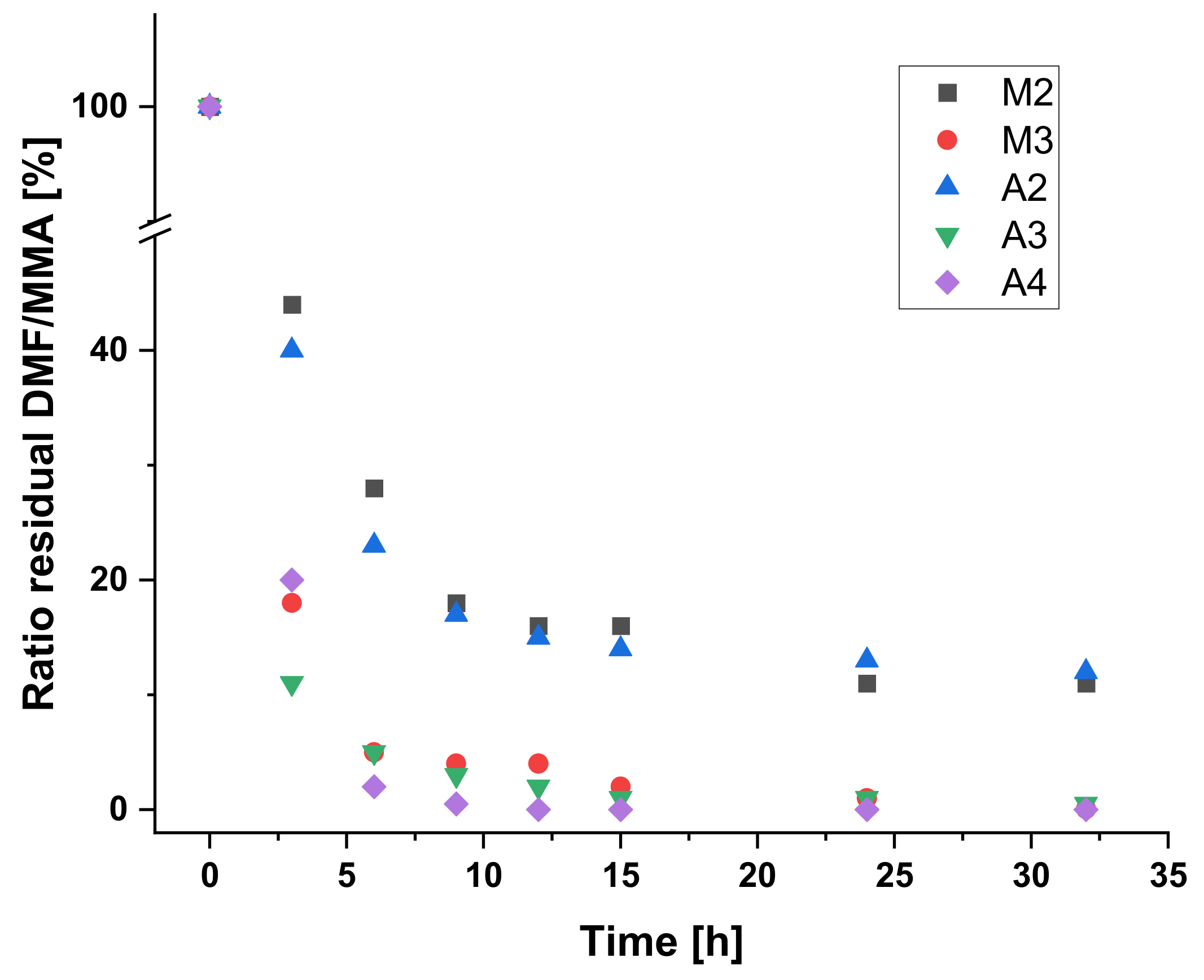
| Time | M2 | M3 | A2 | A3 | A4 | |||||
|---|---|---|---|---|---|---|---|---|---|---|
| (h) | GC | NMR | GC | NMR | GC | NMR | GC | NMR | GC | NMR |
| 0 | 100 | 100 | 100 | 100 | 100 | 100 | 100 | 100 | 100 | 100 |
| 3 | 44 | 39 | 18 | 16 | 40 | 32 | 11 | 12 | 20 | 18 |
| 6 | 28 | 16 | 5 | 5 | 23 | 11 | 5 | 5 | 2 | 2 |
| 9 | 18 | 8 | 4 | 3 | 17 | 6 | 3 | 3 | 0.5 | 0 |
| 12 | 16 | 5 | 4 | 3 | 15 | 4 | 2 | 3 | 0 | 0 |
| 15 | 16 | 2 | 2 | 1 | 14 | 2 | 1 | 0 | 0 | 0 |
| 24 | 11 | 1 | 1 | 1 | 13 | 1 | 1 | 1 | 0 | 0 |
| 32 | 11 | 0 | 0.05 | 0 | 12 | 0 | 0.5 | 1 | 0 | 0 |
© 2020 by the authors. Licensee MDPI, Basel, Switzerland. This article is an open access article distributed under the terms and conditions of the Creative Commons Attribution (CC BY) license (http://creativecommons.org/licenses/by/4.0/).
Share and Cite
Schuett, T.; Kimmig, J.; Zechel, S.; Schubert, U.S. Automated Polymer Purification Using Dialysis. Polymers 2020, 12, 2095. https://doi.org/10.3390/polym12092095
Schuett T, Kimmig J, Zechel S, Schubert US. Automated Polymer Purification Using Dialysis. Polymers. 2020; 12(9):2095. https://doi.org/10.3390/polym12092095
Chicago/Turabian StyleSchuett, Timo, Julian Kimmig, Stefan Zechel, and Ulrich S. Schubert. 2020. "Automated Polymer Purification Using Dialysis" Polymers 12, no. 9: 2095. https://doi.org/10.3390/polym12092095
APA StyleSchuett, T., Kimmig, J., Zechel, S., & Schubert, U. S. (2020). Automated Polymer Purification Using Dialysis. Polymers, 12(9), 2095. https://doi.org/10.3390/polym12092095