Abstract
Polytetrafluoroethylene (PTFE) is a synthetic fluoropolymer known for its excellent hydrophobic properties. In this work, samples from PTFE dispersions with different combinations of water and carbon microparticles were prepared using an electrospraying method. The morphologies and sizes of carbon particles were investigated and the properties of layers including roughness, hydrophobicity and electrical resistivity were investigated. The non-conductive carbon microparticles were selected as a model particle to check the compatibility and electrospraying ability, and it had no effect on the hydrophobic and electrical properties. Carbon microparticles in polymer solution increased the degree of ionization and was found to be beneficial for the shape control of materials. The results showed that PTFE dispersion with the composition of water and carbon microparticles produced fine sphere particles and the layer fabricated with increased roughness. It was also found that the electrical resistivity and hydrophobicity of all the layers comparatively increased. The fabricated microporous layers can be used in various applications like interlining layer in multilayer textile sandwiches.
1. Introduction
Polytetrafluoroethylene (PTFE) is a synthetic fluoropolymer with repeated units , where the inner strongly bonded fluorine atoms make it a high molecular weight compound characterized with semi-crystalline nature, and a strong C-F bond prevents reaction between other chemicals and PTFE [1]. PTFE is known for its excellent hydrophobic, dielectric, mechanical and thermal properties [2]. It is widely used in films, coating materials and fibers in industry domains such as polymeric gears [3], cables [4], implants [5], textiles [6] and so on. Casting PTFE polymer in sphere or PTFE particles via common methods such as molding, emulsion [7], suspension polymerization [8], etc., is very difficult. This is due to the inhomogeneous particle fabrication and a restricted number of processable polymers that cannot be avoided technically. Precipitation [9], spraying drying [10] and supercritical fluid [11] processes are considered to be better options to produce particles. However, it is hard to generate monodisperse particles.
Electrospraying, otherwise called electro-hydrodynamic spraying or electro-hydrodynamic atomization or steady cone-jet mode, is known as a unique technology to produce novel materials including particles, films or coatings [12]. The fundamental mechanism is similar to electrospinning except for the final output. It is a well-established process based on the application of high electrical voltage on the polymer solution of suitable surface tension and viscosity. In this process, the polymer liquid flows out from the capillary nozzle in the applied electric field and then forms a fine jet followed by atomization of polymer liquid into the fine droplets. The particles are collected on a grounded conductive substrate. The degree of ionization in polymer solution affects the shapes and diameters of final polymeric particles during electrospray, which is influenced by the components of the polymer solution. The hydrophobic behavior of the electrospray surface can result from the high surface roughness through reduction of the interfacial energy between solid and liquid [13]. However, a relationship between diameters of PTFE particles and components of PTFE solution will have an effect on sizes, shapes and other properties of PTFE particles produced by electrospraying.
Several research groups have proved that the surface energy of materials was closely related to the surface properties, especially surface roughness [14]. This is a novel way to control material surface wettability. Many theoretical research studies on electrospinning process have been conducted [15,16,17] which showed that distance between nozzle and collector affects morphology, structure, physical and chemical properties of electrospinning fibers and properties based on evaporation rate, deposition time and inconsistency interval. Literature review also revealed that recent research was focused on needle-based electrospraying [18].
The objective of this research was to prepare PTFE microporous layers via electrospraying method [19,20,21] and study its various properties. It would include a study to improve the particles of PTFE by adjusting its solution components and addition of non-conductive carbon microparticles. The relative properties of the prepared PTFE microporous layers including morphology, roughness, hydrophobicity and electrical resistivity were investigated. Addition of carbon microparticles in polymer solution was meant to study the increase in the degrees of ionization and find out if it is beneficial for the compatibility and shape control of materials during electrospinning. In future, it may be possible to add new functionalities via using of activated carbon, conductive carbon or surface coated carbon. The prepared layers can be used for various applications by optimizing the solution and also the spinning parameters.
2. Experimental
2.1. Materials
For this work, Teflon@ PTFE 30 containing 60% wt. PTFE particles and 40% wt. water with surfactant (Chemours, Neu Isenburg, Germany) was used. Tetraethylammonium bromide (TEAB) (Sigma Aldrich, Prague, Czech Republic) was used as salt to increase the conductivity and viscosity of solutions in which the interactions among macromolecules are extensive. A polymer network becomes more solid. It leads to a higher spinning performance of a solution [22,23]. Non-conductive carbon microparticles were milled from pitch-based carbon fiber yarn. The milling process was carried out on a Fritsch pulverisette 7 planetary ball mill. The average size of the carbon microparticle was 1640 nm as shown in Figure 1. The PTFE dispersion was obtained after 24 h-stir of Teflon@ PTFE 30 mixed with TEAB at room temperature. Non-conductive carbon microparticles were added in PTFE solution before electrospraying to functionalize the final PTFE layers. The details of the PTFE dispersion preparation are shown in Table 1.
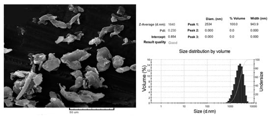
Figure 1.
Morphology and size distribution of carbon microparticles.

Table 1.
Description of PTFE Dispersion (%) Based on different Compositions.
2.2. Preparation of PTFE Microporous Layers
The Nanospider instrument (Figure 2) is a needleless electrospinning system that was used to prepare the PTFE layers by electrospraying method. Its parts include a high-voltage supplier, solution tank, rotating roller electrode, grounded collector and support material. During the electrospraying process, the electrostatic force produced between the high-voltage supplier and grounded collector draw the charged polymer solution into forms of particles which will be collected on the surface of support material. The electro-rotating cylinder keeps the electrospraying process ongoing to continuously produce the particles and the even layer of particles is obtained with coordination of the movement of support material.
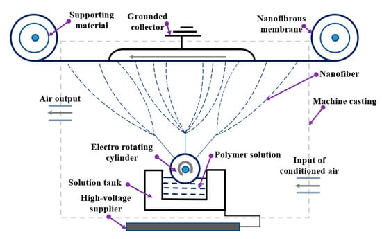
Figure 2.
Schematic diagram of the electrospraying method (Nanospider).
The PTFE solution was first prepared to be used for electrospraying. As PTFE was insoluble in water, it was introduced in particle form in the water-based dispersion. During the electrospraying process, the PTFE dispersion was drawn to the form layer being collected on the surface of support materials. The particles and their layers are marked as P1, P2, P3 and P4 corresponding to PTFE dispersion S1, S2, S3 and S4. The spinning parameters, including substrate speed (mm/min), applied voltage of high-voltage supplier and grounded voltage (kV), speed of electrode (rev/min), the temperature of air (°C) and the relative humidity (%). The suitable parameters for producing PTFE layers were optimized and selected shown in Table 2. To achieve the optimized conditions, different combinations of solutions were prepared and trialed on Nanospider to set the spinning parameters. The adjusting of process parameters was necessary for the needleless electrospinning system of Nanospider for preparation of layers with tunable porosity.
Table 2.
Spinning parameters.
2.3. Characterization of PTFE Microporous Layers
2.3.1. Morphologies
To observe the attachment of the PTFE microporous layer to the surface of support materials, scanning electron microscope (SEM), VEGA TESCAN Inc., Lincoln, NE, USA, was used. The HORIBA laser scattering particle size distribution analyzer LA-920 was used to analyze the size distribution of PTFE particles produced by various PTFE solutions as described in Table 1. The refractive index was set as 1.6. Mean size and S.D. size were calculated as well.
2.3.2. Roughness of PTFE Microporous Layers
The roughness of PTFE layers was tested using the OLS5000 LEXT measuring laser microscope. During the test, every ten different lines of the scanned PTFE layers were recorded and then calculated automatically into the main roughness parameters including arithmetic average height (), root mean square roughness (), skewness () and kurtosis (), as seen in Figure 2. The , known as the central line average (CLA), is the most universal parameter for general roughness control given by Equation (1). is the parameter describing the standard deviation of the distribution of surface heights and is given by Equation (2). , and are separately obtained by Equations (3) and (4). is used to measure the symmetry of profile about the mean line and is very sensitive to peak or valley height. The point is that will be positive if the profile has more high peaks or flat valleys and, oppositely, the profile with few peaks gives negative values, contributing to distinguishing the different profiles with the same and . describes the sharpness of the probability density of the profile. If , the profile will have relatively few high peaks and low valleys and, oppositely, the profile will have relatively more high peaks and low valleys with .
where x is the direction of calculation, is the reference length along x direction and is the height at x position.
2.3.3. Contact Angle Analysis
A See System E instrument is a portable computer-based instrument to measure the contact angle with a special purpose software following ISO 27448:2009 test method. Before measuring, the samples were washed for 6 mins in distilled water to remove the salts and were dried at room temperature. Deionized water was dropped onto each PTFE layer from a needle on a microsyringe (5 µL) and a picture of the drop was taken. The contact angles could be calculated by analyzing the shape of the drop, which is displayed in the PC. In total, 10 drops were measured for each sample. Two minutes were allowed from the time of water drop until the measurement of the contact angle.
2.3.4. Electrical Resistance
Electrical resistance measurement was done on a 4339B High resistance meter (Hewlett Packard ohmmeter) measuring device shown in Figure 3. Calibration of the instrument (high resistance meter) is done using a standard plate of known electrical resistivity. The electrical surface and volume resistivity of the samples produced were measured according to the standard ASTM D257-07(2007) at the voltage of 100 V, at a temperature of 22.3 °C, and at a relative humidity (RH) of 40.7%. The measurement results were recorded 60 s after the electrodes were placed on the textile samples. The volume resistivity was measured by applying a voltage potential across opposite sides of the sample and measuring the resultant current through the sample. Volume resistivity ρν (Ω mm) was calculated from the following Equation (5):
where Rv(Ω) is volume resistivity reading, t is thickness of the fabric (mm), and S is the surface area of the electrodes (mm2).
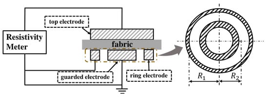
Figure 3.
Schematic diagram of an experimental setup to measure electrical resistance.
Surface resistivity is measured by applying a voltage potential between two electrodes of specified configuration that are in contact with the same side of a material under test (Figure 4). Surface resistivity ρs (Ω) was calculated from Equation (6):
where RS (Ω) is the surface resistance reading, R1 is the outer radius of the center electrode (mm), and R2 is the inner radius of the outer ring electrode (mm), where R1 = 58 mm and R2 = 51 mm.
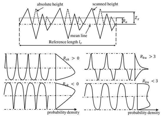
Figure 4.
Description of roughness parameters.
3. Results and Discussions
3.1. Morphology of Microporous Layers
The particles on the surface of the substrate were observed in Figure 5 and their size distribution is shown in Figure 6. The layers produced from all combinations of PTFE solution ranges from 0.1–10 which proves that the particles are in the range of microns. Figure 5(a2,c2) and Figure 6a,c show the PTFE microporous layers, where the final PTFE product appears in the form of a sphere and has larger sizes when there is more H2O in PTFE aqueous solution. In Figure 5(b2), all the layers appear in the form of a sphere as well, which possibly resulted from the carbon microparticles in PTFE polymers. In Figure 5(d2), the particles are almost spherical, but the diameters tend to decrease when compared with Figure 5(b2), which can also be proved by comparing Figure 6b or Figure 6d, suggesting that PTFE dispersion with carbon microparticles and higher water content has the ability to produce fine layers via electrospraying method, which is due to the change of viscosity and surface tension of the solution [24,25,26,27]. Also, the presence of surfactant in the PTFE emulsion attributes to the change in fiber diameter. The formation of finer fibers is facilitated by the presence of surfactant in the solution which increased the conductivity of the solution and decreased the surface tension [28]. The morphology of the microporous membrane depends, on the temperature, solvent, voltage, physical properties of liquid phase, distance of collector, doping agents and the time of solvent evaporation. The fibers tend to form beadlike structures when the concentration of the polymer solution is lower [29,30].
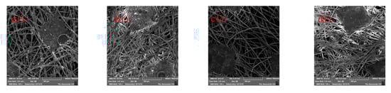
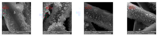
Figure 5.
Scanning electron microscope images of PTFE layers (P1: a1,a2; P2: b1,b2; P3: c1,c2; and P4: d1,d2).
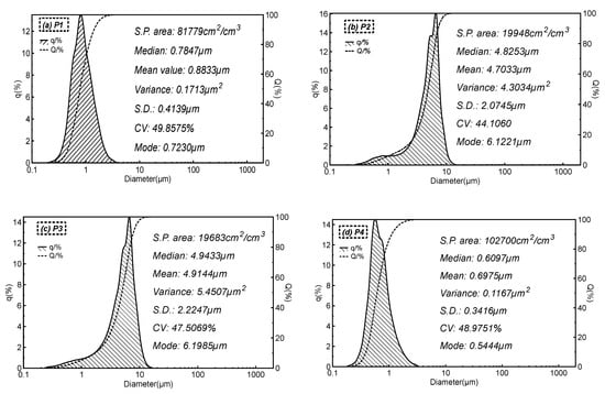
Figure 6.
Size distribution of particles (q: density distribution of the particle size; Q: cumulative distribution of the particle size). (a) P1; (b) P2; (c) P3; and (d) P4)
3.2. Roughness of PTFE Microporous Layers
Exact distribution of the PTFE layer on the surface of support materials is explained by roughness. Table 3 shows the key parameters of roughness of the PTFE layer, and the 3D morphology of the PTFE microporous layer is shown in Figure 6. PTFE layers P1 and P3, which were separately produced by the S1 and S3 solutions, have the similar surface roughness parameters, shown in Table 3, and the 3D morphologies of the P1 and P3 layers are almost the same as those seen in Figure 7a,c. The mean values are much smaller than others, suggesting that the PTFE layer does not have a rough surface compared with the P2 and P4 layers, which may possibly result in a smoother particle shape. However, the P3 layers have values which are smaller than 3, and partial P3 layers have values which are bigger than 3, suggesting that its surface roughness has two kinds of characters. For P2 layers, the mean value increases when compared with P1 and P3 layers, which is caused by carbon microparticles in the PTFE polymer, and Figure 7b proves it well. However, all the surface roughness parameters of the P2 layers have no essential difference from the P1 and P3 PTFE layers, and the is negative and all the values are bigger than 3. The mean value of the P4 layers increases a lot and reaches 14.617, meaning that it has the largest surface roughness. The P4 layers have a positive mean value and an mean value which is smaller than 3, suggesting that the P4 layer surface is totally different from that of the other three particle layers. Figure 7d shows that the P4 layer tends to be sunken and its surface is even. As described in Section 3.1, with PTFE dispersed in water and with the addition of the right amount of water, the viscosity and the surface tension were adjusted, which in turn led to more evenness of the layers.
Table 3.
Roughness of PTFE microporous layers.
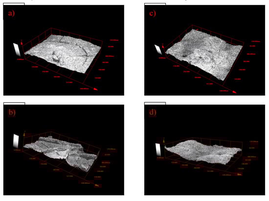
Figure 7.
3D morphology of the PTFE microporous layer (a) P1; (b) P2; (c) P3; and (d) P4).
3.3. Influence on Hydrophobicity
The results of the static contact angle measurements are shown in Figure 8 and the digital images of contact angle measurement is shown in Figure 9. The contact angles are over 90°, which proves that all of the particle layers are hydrophobic. The P1 and P2 layers have a close mean value of contact angles, which may be caused by the similarly low and values. The P3 and P4 layers have a close higher contact angle. The P4 layer has a contact angle of about 140°. This is because of its high , given its high contact angle, and values smaller than 3 improve the uniformity of its surface roughness. The surface roughness of the P3 layer explained in Section 3.2 is complex because the P3 layer has values which are bigger than 3 and other parts have values that are smaller than 3. This complex surface roughness of P3 may lead to higher contact angles than those of P4, but the difference is small. As explained in Section 3.2, the adjusted surface tension, evenness and surface roughness of the electrosprayed layer attributes to the hydrophobicity. As seen in Figure 8, samples P3 and P4 showed improved hydrophobicity. Changes in contact angle after 6 minutes of washing (see Figure 8) is probably due to time-dependent partial removal of a water-soluble component other than PTFE which was part of the original PTFE dispersion.
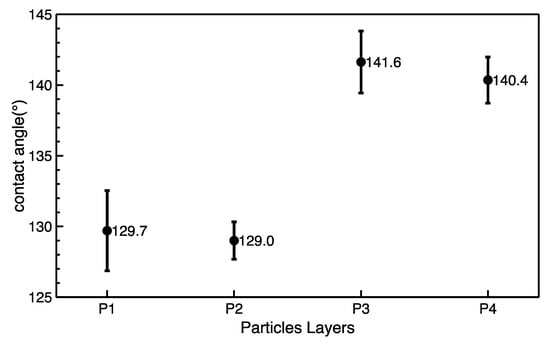
Figure 8.
Contact angles after 6 minutes of washing of as-prepared PTFE layers.
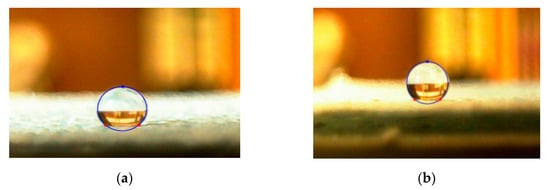
Figure 9.
Images of the contact angle measurement: (a) 135.3°; (b) 142.3°.
Stability test under washing in standard conditions was conducted for the PTFE layers. It was found that the morphology of layers was the same.
3.4. Influence of Electrical Property on Microporous Layers
The thickness and final electrical resistivity values of microporous layers are shown in Table 4. The surface resistivity and volume resistivity of all the layers range in 109 Ω, which means that all of the layers belong to the antistatic body. From the definition of , the is the key parameter suggesting the distribution of the continuous layers of materials. The relationship between and resistivity is shown in Figure 10. Surface resistivity slightly decreases with increasing , which means that the uniform layers of PTFE increase slightly to improve the movement of electric charges during the resistivity tests. Similarly, the uniform layers of materials also account for volume resistivity, and the volume resistivity values tend to decrease with increasing values. Besides, no clear relationships between contents of carbon microparticles and electrical properties can be found due to the non-conductive property of the carbon microparticles.
Table 4.
Resistivity values of PTFE layers.
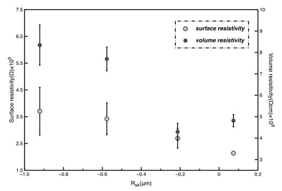
Figure 10.
Relationship between resistivity and Rsk.
4. Conclusions
Electrosprayed layers were fabricated from optimized concentration of the solution via electrospraying using the Nanospider instrument. PTFE particles containing carbon microparticles appear in the form of spheres and tend to be smaller with dilution of the PTFE solution. Compared to carbon microparticles added in the PTFE solution, the water content had a greater effect on the surface roughness. An increase of the contact angles of the layers was observed. Surface resistivity and volume resistivity values ranging in 109 Ω were obtained, suggesting that the particle layers were antistatic. Non-conductive carbon microparticles have no significant influence on electrical properties of the layers. However, adding carbon microparticles in polymer solution increased the degrees of ionization and was found to be beneficial for the shape control of materials during electrospraying. By optimizing conditions, more hydrophobic layers can also be achieved.
Author Contributions
Conceptualization, M.V.; methodology, M.V.; validation, M.V., K.Y. and X.X.; formal analysis, M.V.; investigation, M.V.; resources, M.V.; data curation, M.V.; writing—original draft preparation, M.V.; writing—review and editing, M.V., J.M. and G.Z. (Guocheng Zhu); visualization, J.Y., Y.W. and G.Z. (Guoqing Zhang); supervision, J.M.; project administration, D.K. and J.M.; funding acquisition, D.K. All authors have read and agreed to the published version of the manuscript.
Funding
This research received no external funding.
Acknowledgments
This work was supported by the Ministry of Education, Youth and Sports of the Czech Republic and the European Union-European Structural and Investment Funds in the Frames of Operational Programme Research, Development and Education-project Hybrid Materials for Hierarchical Structures (HyHi, Reg. No. CZ.02.1.01/0.0/0.0/16_019/0000843), the project “Intelligent thermoregulatory fibers and functional textile coatings based on temperature resistant encapsulated PCM” SMARTTHERM (Project No. TF06000048) and the projects “Ministry of Education, Youth and Sports in the frames of support for researcher mobility” (VES19China-mobility, Czech-Chinese cooperation) and “Design of multi-layer micro/nano fibrous structures for air filters applications”, reg. no. 8JCH1064.
Conflicts of Interest
The authors declare no conflict of interest.
References
- Bodnár, E.; Grifoll, J.; Rosell-Llompart, J. Polymer solution electrospraying: A tool for engineering particles and films with controlled morphology. J. Aerosol Sci. 2018, 125, 93–118. [Google Scholar] [CrossRef]
- Butt, H.J.; Graf, K.; Kappl, M. Thin films on surfaces of liquids. In Physics and Chemistry of Interfaces; Wiley: Hoboken, NJ, USA, 2003; pp. 280–298. [Google Scholar]
- Yuan, X.D.; Yang, X.J. A study on friction and wear properties of PTFE coatings under vacuum conditions. Wear 2010, 269, 291–297. [Google Scholar] [CrossRef]
- Light, D.N.; Wilcox, J.R. Process Considerations in the Fabrication of Fluoropolymer Printed Circuit Boards. IEEE Trans. Compon. Packag. Manuf. Technol. Part A 1995, 1, 118–126. [Google Scholar] [CrossRef]
- Zhao-Zhu, Z.; Wei-Min, L. Study on the friction and wear properties of glass fabric composites filled with nano- and micro-particles under different conditions. Mater. Sci. Eng. A 2005, 392, 359–365. [Google Scholar]
- Huang, F.; Wei, Q.; Liu, Y.; Gao, W.; Huang, Y. Surface functionalization of silk fabric by PTFE sputter coating. J. Mater. Sci. 2007, 42, 8025–8028. [Google Scholar] [CrossRef]
- Nomura, M.; Tobita, H.; Suzuki, K. Emulsion polymerization: Kinetic and mechanistic aspects. Adv. Polym. Sci. 2005, 175, 1–128. [Google Scholar]
- Manziek, L.; Langenmayr, E.; Lamola, A.; Gallagher, M.; Brese, N.; Annan, N. Functionalized Emulsion and Suspension Polymer Particles: Nanoreactors for the Synthesis of Inorganic Materials. Chem. Mater. 1998, 10, 3101–3108. [Google Scholar] [CrossRef]
- Kasai, H.; Nalwa, H.S.; Oikawa, H.; Okada, S.; Matsuda, H.; Minami, N.; Kakuta, A.; Ono, K.; Mukoh, A.; Nakanishi, H. A novel preparation method of organic microcrystals. Jpn. J. Appl. Phys. 1992, 31, L1132–L1134. [Google Scholar] [CrossRef]
- Mu, L.; Feng, S.S. Fabrication, characterization and in vitro release of paclitaxel (Taxol®) loaded poly (lactic-co-glycolic acid) microspheres prepared by spray drying technique with lipid/cholesterol emulsifiers. J. Control. Release 2001, 76, 239–254. [Google Scholar] [CrossRef]
- Yeo, S.D.; Kiran, E. Formation of polymer particles with supercritical fluids: A review. J. Supercrit. Fluid. 2005, 34, 287–308. [Google Scholar] [CrossRef]
- Dhanumalayan, E.; Joshi, G.M. Performance properties and applications of polytetrafluoroethylene (PTFE)—A review. Adv. Compos. Hybrid. Mater. 2018, 1, 247–268. [Google Scholar] [CrossRef]
- Isık, T.; Demir, M.M.; Aydogan, C.; Ciftci, M.; Yagci, Y. Hydrophobic coatings from photochemically prepared hydrophilic polymethacrylates via electrospraying. J. Polym. Sci. Part A Polym. Chem. 2017, 55, 1338–1344. [Google Scholar] [CrossRef]
- Meiron, T.S.; Marmur, A.; Saguy, I.S. Contact angle measurement on rough surfaces. J. Colloid. 2004, 274, 637–644. [Google Scholar] [CrossRef] [PubMed]
- Shin, Y.M.; Hohman, M.M.; Brenner, M.P.; Rutledge, G.C. Experimental characterization of electrospinning: The electri-cally forced jet and instabilities. Polymer 2001, 42, 09955–09967. [Google Scholar] [CrossRef]
- Yarin, A.L.; Koombhongse, S.; Reneker, D.H. Bending instability in electrospinning of nanofibers. J. Appl. Phys. 2001, 89, 3018–3026. [Google Scholar] [CrossRef]
- Long, Q.; Cai, M.; Li, J.; Rong, H.; Jiang, L. Improving the electrical catalytic activity of Pt/TiO2 nanocomposites by a combination of electrospinning and microwave irradiation. J. Nanopart. Res. 2010, 13, 1655–1662. [Google Scholar] [CrossRef]
- Venkataraman, M.; Mishra, R.; Marek, J.; Kucerova, K.; Militky, J. Aerogel embedded electrospun nanofiber layers for thermal insulation. In Textile Bioengineering and Informatics Symposium Proceedings, Proceedings of the 10th Textile Bioengineering and Informatics Symposium, (TBIS 2017), Wuhan, China, 16—19 May 2017; Wuhan Textile University: Wuhan, China, 2017; pp. 745–750. [Google Scholar]
- Burkarter, E.; Saul, C.K.; Thomazi, F.; Cruz, N.C.; Zanata, S.M.; Roman, L.S.; Schreiner, W.H. Electrosprayed superhydrophobic PTFE: A non-contaminating surface. J. Phys. D Appl. Phys. 2007, 40, 7778–7781. [Google Scholar] [CrossRef]
- Venkataraman, M.; Mishra, R.; Subramaniam, V.; Gnanamani, A.; Kotresh, T.M.; Militky, J. Dynamic heat flux measurement for advanced insulation materials. Fibers Polym. 2016, 17, 925–931. [Google Scholar] [CrossRef]
- Burkarter, E.; Saul, C.K.; Thomazi, F.; Cruz, N.C.; Roman, L.S.; Schreiner, W.H. Superhydrophobic electrosprayed PTFE. Surf. Coat. Technol. 2007, 202, 194–198. [Google Scholar] [CrossRef]
- Venkataraman, M.; Mishra, R.; Yang, K.; Militky, J.; Kremenakova, D.; Zhu, G.; Yao, J. Preparation of electrosprayed microporous membranes. In IOP Conference Series: Materials Science and Engineering, Proceedings of the 18th World Textile Conference (AUTEX 2018), Istanbul, Turkey, 20–22 June 2018; IOP Publishing: Bristol, UK, 2018; Volume 460. [Google Scholar]
- Venkataraman, M.; Mishra, R.; Militky, J.; Xiong, X.; Marek, J.; Yao, J.; Zhu, G. Electrospun nanofibrous membranes embedded with aerogel for advanced thermal and transport properties. Polym. Adv. Technol. 2018, 29, 2583–2592. [Google Scholar] [CrossRef]
- Sukigara, S.; Gandhi, M.; Ayutsede, J.; Micklus, M.; Ko, F. Regeneration of Bombyxmori silk by electrospinning—Part 1: Processing parameters and geometric properties. Polymer 2003, 44, 5721. [Google Scholar] [CrossRef]
- Ahn, Y.C.; Park, S.K.; Kim, G.T.; Hwang, Y.J.; Lee, C.G.; Shin, H.S.; Lee, J.K. Development of high efficiency nanofilters made of nanofibers. Curr. Appl. Phys. 2006, 6, 1030. [Google Scholar] [CrossRef]
- Fong, H.; Chun, I.; Reneker, D.H. Beaded nanofibers formed during electrospinning. Polymer. 1999, 40, 4585. [Google Scholar] [CrossRef]
- Lee, K.H.; Kim, H.Y.; Bang, H.J.; Jung, Y.H.; Lee, S.G. The change of bead morphology formed on electrospun polystyrene fibers. Polymer. 2003, 44, 4029. [Google Scholar] [CrossRef]
- Lin, K.; Chua, K.N.; Christopherson, G.T.; Lim, S.; Mao, H.Q. Reducing electrospun nanofiber diameter and variability using cationicamphiphiles. Polymer 2007, 48, 6384. [Google Scholar] [CrossRef]
- Jaworek, A. Electrospray droplet sources for thin film deposition. J. Mater. Sci. 2007, 266–297. [Google Scholar] [CrossRef]
- Venkataraman, M.; Mishra, R.; Militky, J.; Wiener, J.; Kucerova, K.; Marek, J.; Arumugam, V. Optimization of microporous hydrophobic membranes by electrospraying. In Proceedings of the 9th International Conference on Nanomaterials—Research and Application, (NANOCON 2017), Brno, Czech Republic, 18–20 October 2017; Volume 2017, pp. 877–8859. [Google Scholar]
© 2020 by the authors. Licensee MDPI, Basel, Switzerland. This article is an open access article distributed under the terms and conditions of the Creative Commons Attribution (CC BY) license (http://creativecommons.org/licenses/by/4.0/).