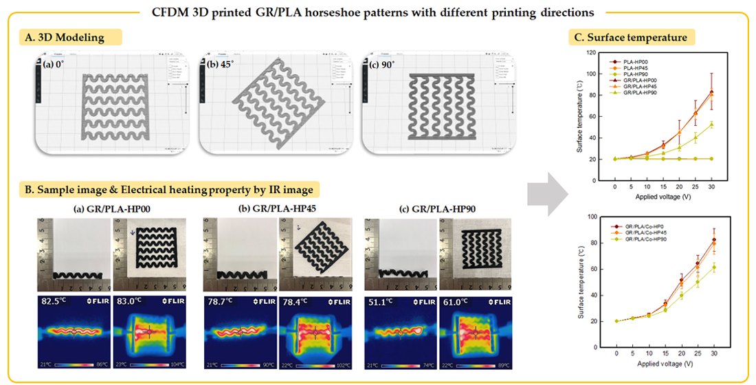
Characterization of Electrical Heating Performance of CFDM 3D-Printed Graphene/Polylactic Acid (PLA) Horseshoe Pattern with Different 3D Printing Directions


Abstract
:
1. Introduction
2. Materials and Methods
2.1. Materials
2.2. Preparation of CFDM 3D-Printed Horseshoe Pattern
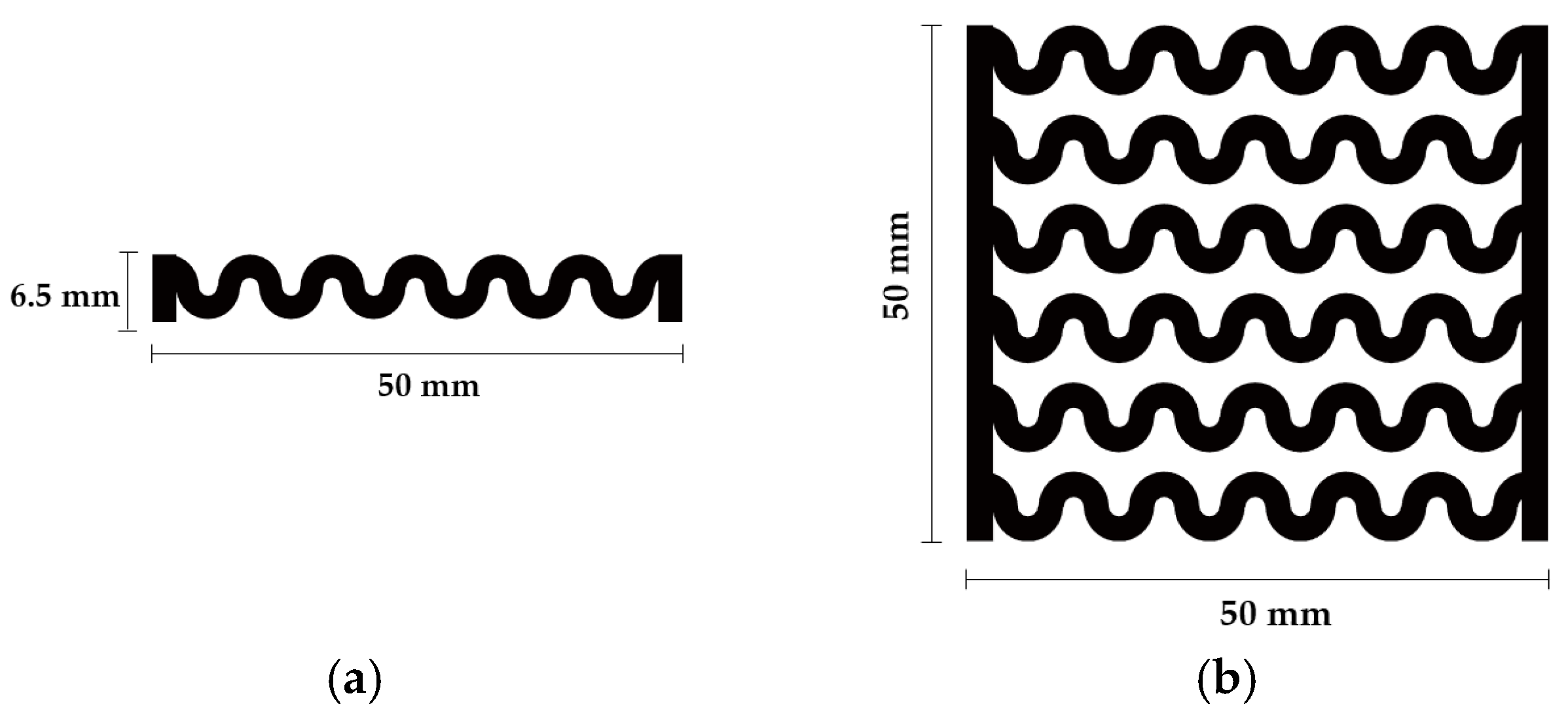
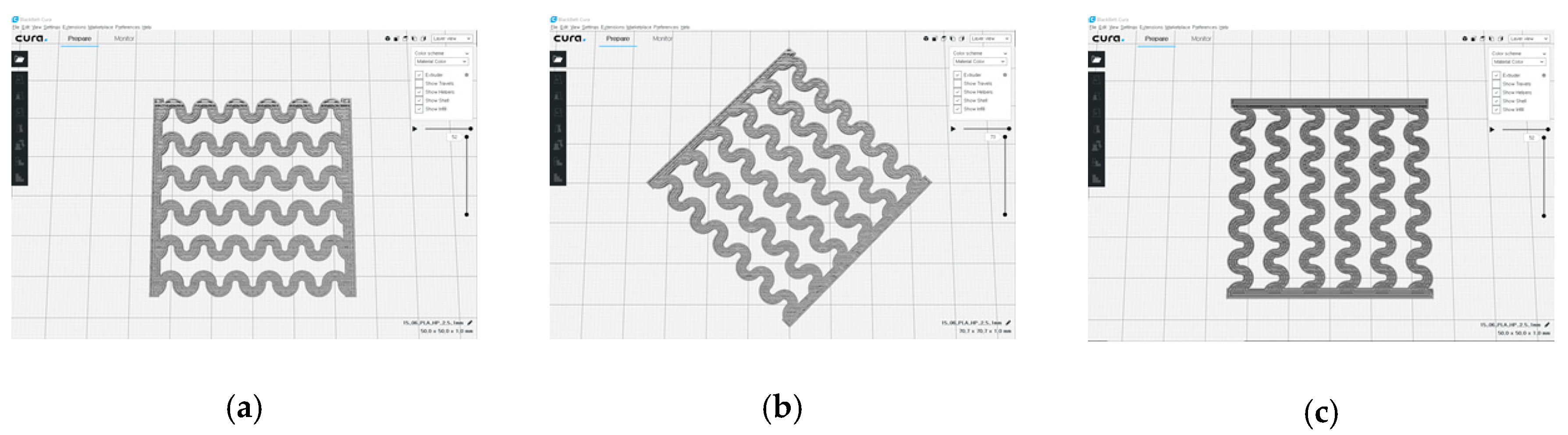
2.2.1. Design and 3D Modeling of Horseshoe Pattern
2.2.2. CFDM 3D Printing Conditions
2.3. Preparation of CFDM 3D-Printed Horseshoe Pattern/Cotton Composite Fabric
2.4. Characterization
2.4.1. Morphology
2.4.2. X-ray Diffraction (XRD)
2.4.3. Surface Resistivity
2.4.4. Electrical Heating Property
3. Results and Discussion
3.1. Morphology of CFDM 3D-Printed Horseshoe Pattern Manufactured with Different 3D Printing Directions
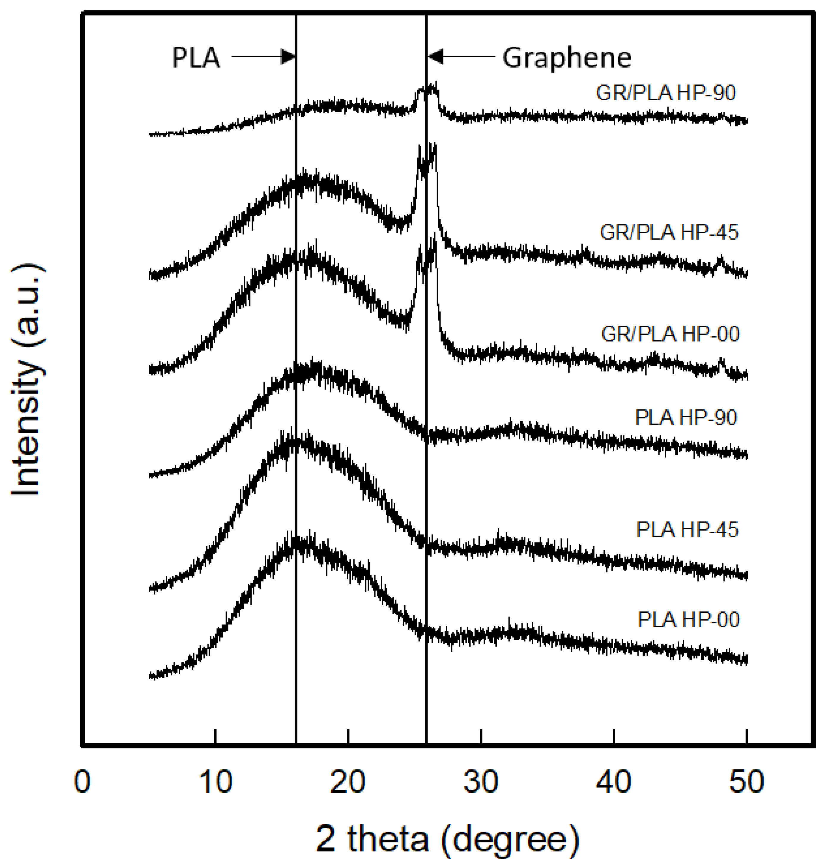
3.2. XRD Analysis of CFDM 3D-Printed Horseshoe Pattern Manufactured with Different 3D Printing Directions
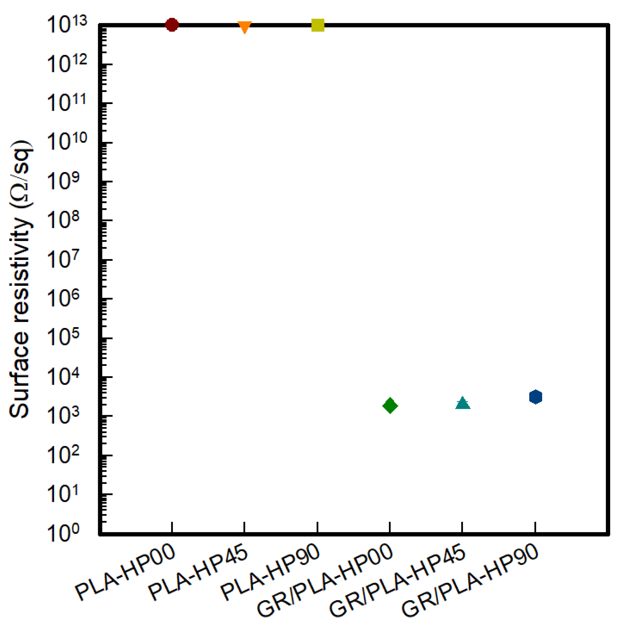
3.3. Surface Resistivity of CFDM 3D-Printed Horseshoe Pattern Manufactured with Different 3D Printing Directions
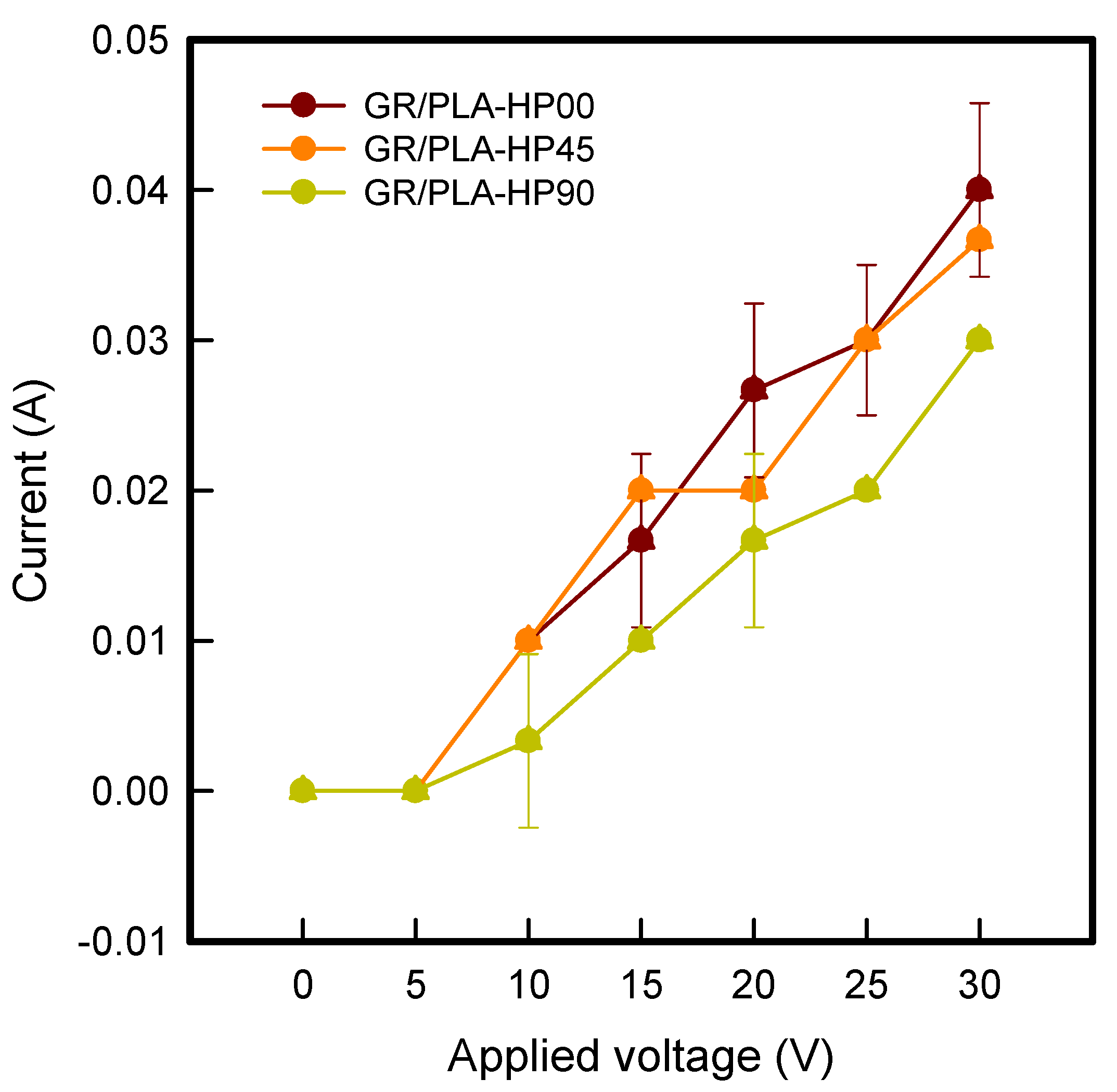
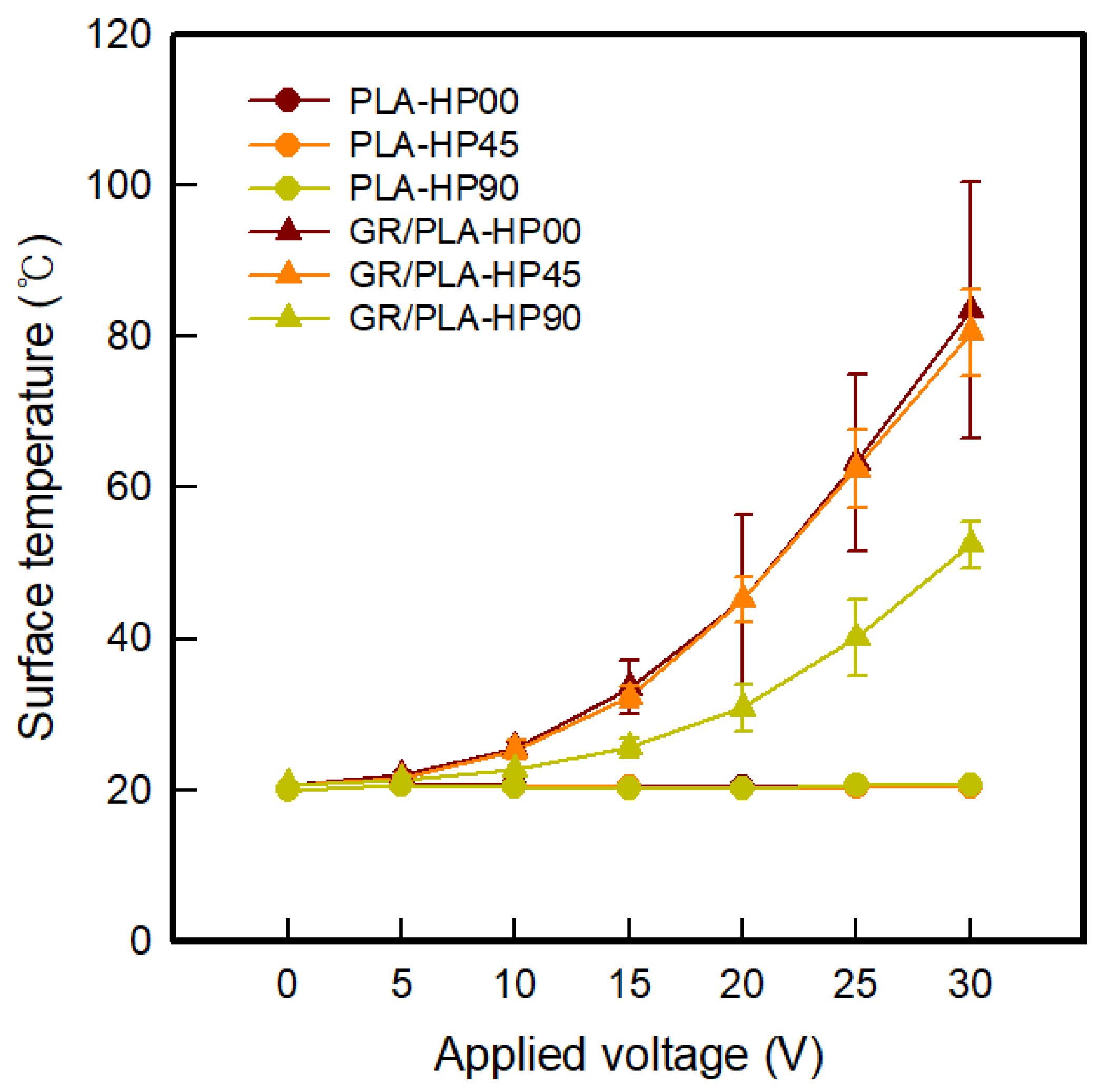
3.4. Electrical Heating Properties of CFDM 3D-Printed Horseshoe Pattern Manufactured with Different 3D Printing Directions
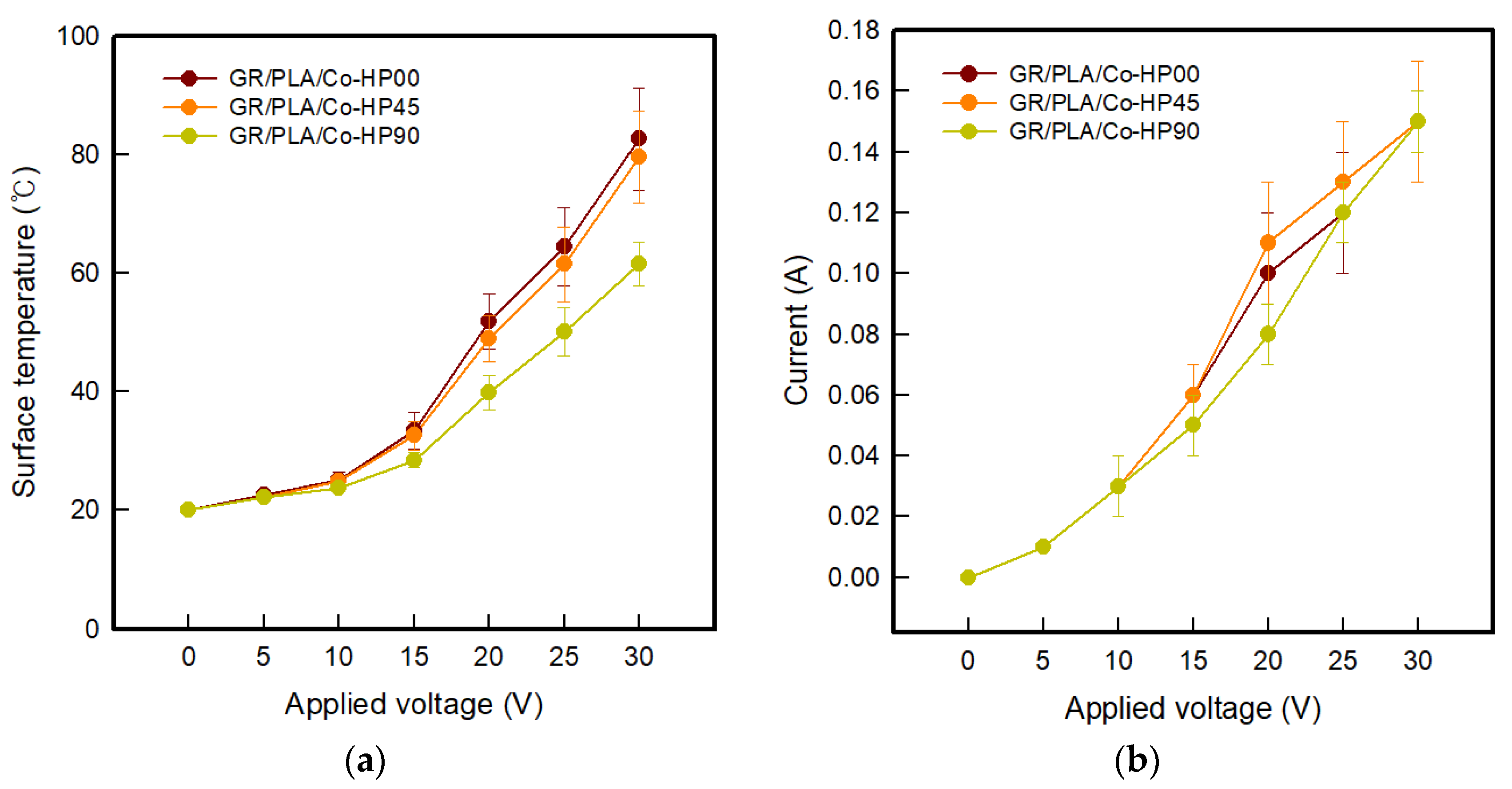
3.5. Electrical Heating Properties of CFDM 3D-Printed Horseshoe Pattern Printed on Cotton Fabric
4. Conclusions
Author Contributions
Funding
Conflicts of Interest
References
- Ngo, T.D.; Kashani, A.; Imbalzano, G.; Nguyen, K.T.Q.; Hui, D. Additive manufacturing (3D printing): A review of materials, methods, applications and challenges. Compos. B Eng. 2018, 143, 172. [Google Scholar] [CrossRef]
- Liu, Z.; Wang, Y.; Wu, B.; Cui, C.; Guo, Y.; Yan, C. A critical review of fused deposition modeling 3D printing technology in manufacturing polylactic acid parts. Int. Adv. Manuf. Technol. 2019, 102, 2877. [Google Scholar] [CrossRef]
- Chatterjee, K.; Ghosh, T.K. 3D printing of textiles: Potential roadmap to printing with fibers. Adv. Mater. 2019, 32, 1902086. [Google Scholar] [CrossRef] [PubMed]
- Kim, S.G.; Kim, H.R. The recent tendency of fashion textiles by 3D printing. Fashion Text. Res. J. 2018, 20, 117. [Google Scholar] [CrossRef]
- Kim, H.; Lee, S. Characterization of electrical heating of graphene/PLA honeycomb structure composite manufactured by CFDM 3D printer. Fash. Text. 2020, 7, 1–18. [Google Scholar] [CrossRef]
- Kalsoom, U.; Nesterenko, P.N.; Paull, B. Recent developments in 3D printable composite materials. RSC Adv. 2016, 6, 60355. [Google Scholar] [CrossRef]
- Espera, A.H.; Dizon, J.R.C.; Chen, Q.; Advincula, R.C. 3D-printing and advanced manufacturing for electronics. Prog. Addit. Manufact. 2019, 4, 245. [Google Scholar] [CrossRef]
- Foster, C.W.; Down, M.P.; Zhang, Y.; Ju, X.; Rowley-Neale, S.J.; Smith, G.C.; Kelly, P.J.; Banks, C.E. 3D printed graphene based energy storage devices. Sci. Rep. 2017, 7, 42233. [Google Scholar] [CrossRef]
- Kamyshny, A.; Magdassi. Conductive nanomaterials for 2D and 3D printed flexible electronics. Chem. Soc. Rev. 2019, 48, 1712. [Google Scholar] [CrossRef]
- Lee, J.; Kim, H.-C.; Choi, J.-W.; Lee, I.H. A review on 3D printed smart devices for 4D printing. Int. J. Pr. Eng. Man-GT 2017, 4, 373. [Google Scholar] [CrossRef]
- Chen, G.; Wang, H.; Zhao, W. Fabrication of highly ordered polymer/graphite flake composite with eminent anisotropic electrical property. Polm. Adv. Technol. 2018, 19, 1113. [Google Scholar] [CrossRef]
- Marsden, A.J.; Papageorgiou, D.G.; Vallés, C.; Liscio, A.; Palermo, V.; Bissett, M.A.; Young, R.J.; Kinoch, I.A. Electrical percolation in graphene-polymer composites. 2D Mater. 2018, 5, 032003. [Google Scholar] [CrossRef] [Green Version]
- Spinelli, G.; Kotsilkova, R.; Ivanov, E.; Petrova-Doycheva, I.; Menseidov, D.; Georgiev, V.; Maio, R.D.; Silvestre, C. Effects of filaments extrusion, 3D printing and hot-pressing on electrical and tensile properties of poly(lactic) acid composites filled with carbon nanotubes and graphene. Nanomaterials 2020, 10, 35. [Google Scholar] [CrossRef] [PubMed] [Green Version]
- Watschke, H.; Hilbig, K.; Vietor, T. Design and characterization of electrically conductive structures additively manufactured by material extrusion. Appl. Sci. 2019, 9, 779. [Google Scholar] [CrossRef] [Green Version]
- Zhang, D.; Chi, G.; Li, B.; Gao, Z.; Du, Y.; Guo, J.; Wei, J. Fabrication of highly conductive graphene flexible circuits by 3D printing. Synth. Met. 2016, 217, 79. [Google Scholar] [CrossRef]
- Kim, H.; Lee, S. Characterization of carbon nanofiber (CNF)/polymer composite coated on cotton fabrics prepared with various circuit patterns. Fash. Text. 2018, 5, 7. [Google Scholar] [CrossRef]
- Kim, H.; Lee, S.; Kim, H. Electrical heating performance of electro-conductive para-aramid knit manufacture by dip-coating in a graphene/waterborne polyurethane composite. Sci. Rep. 2019, 9, 1511. [Google Scholar] [CrossRef] [Green Version]
- Kim, H.; Lee, S. Electrical heating properties of various electro-circuit patterns coated on cotton fabric using graphene/polymer composites. Text. Res. J. 2019, 89, 4114. [Google Scholar] [CrossRef]
- Kim, H.; Lee, S. Characterization of electrical heating textile coated by graphene nanoplatelets/PVDF-HFP composite with various high graphene nanoplatelet contents. Polymers 2019, 11, 928. [Google Scholar] [CrossRef] [Green Version]
- Haney, R.; Tran, P.; Trigg, E.B.; Koerner, H.; Dickens, T.; Ramakrishnan, S. Printability and performance of 3D conductive graphite structures. Addit. Manuf. 2020. [Google Scholar] [CrossRef]
- Zhang, J.; Yang, B.; Fu, F.; You, F.; Dong, X.; Dai, M. Resistivity and its anisotropy characterization of 3D-printed acrylonitrile butadiene styrene copolymer (ABS)/Carbon black (CB) Composites. Appl. Sci. 2017, 7, 20. [Google Scholar] [CrossRef] [Green Version]


| Parameters | PLA | GR/PLA |
|---|---|---|
| Belt offset (mm) | 0.2 | 0.2 |
| Layer height (mm) | 1.8 | 1.8 |
| Temperature of nozzle (°C) | 215 | 220 |
| Temperature of bed (°C) | 75 | 50 |
| Printing speed (mm/s) | 40 | 30 |
| Infill speed (mm/s) | 30 | 22.5 |
| Infill (%) | 100 | 100 |
| Gantry angle (°) | 15 | 15 |
| 3D Printing Direction | PLA | GR/PLA | ||
|---|---|---|---|---|
| Sample Code | Digital Image | Sample Code | Digital Image | |
| 0° | PLA-HP00 |  | GR/PLA-HP00 |  |
| 45° | PLA-HP45 |  | GR/PLA-HP45 |  |
| 90° | PLA-HP90 | 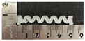 | GR/PLA-HP90 |  |
| 3D Printing Direction | Sample Code | Digital Image |
|---|---|---|
| 0° | GR/PLA/Co-HP00 |  |
| 45° | GR/PLA/Co-HP45 | 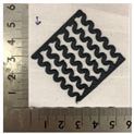 |
| 90° | GR/PLA/Co-HP90 | 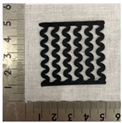 |
| Measured Part | Magnification | Sample Code | ||
|---|---|---|---|---|
| PLA-HP00 | PLA-HP45 | PLA-HP90 | ||
| Digital image |  |  |  | |
| Surface | ×6.5 |  |  |  |
| Lateral |  |  |  | |
| Measured Part | Magnification | Sample Code | ||
| GR/PLA-HP00 | GR/PLA-HP45 | GR/PLA-HP90 | ||
| Digital image |  |  |  | |
| Surface | ×6.5 |  |  |  |
| Lateral |  |  |  | |
| Measured Part | Magnification | Sample Code | ||
| PLA-HP00 | PLA-HP45 | PLA-HP90 | ||
| Surface | ×300 | 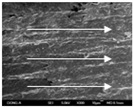 |  |  |
| ×1000 |  | 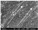 |  | |
| ×10,000 |  |  |  | |
| ×15,000 |  |  |  | |
| Measured Part | Magnification | Sample Code | ||
| GR/PLA-HP00 | GR/PLA-HP45 | GR/PLA-HP90 | ||
| Lateral | ×300 |  |  | 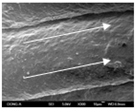 |
| ×1000 |  |  |  | |
| ×10,000 |  |  |  | |
| ×15,000 |  |  |  | |
| PLA-HP00 | Applied Voltage (V) | |||||
| 5 | 10 | 15 | 20 | 25 | 30 | |
| IR image |  |  |  |  |  |  |
| Mean temperature (°C) | 20.5 ± 0.2 | 20.5 ± 0.2 | 20.3 ± 0.3 | 20.4 ± 0.1 | 20.3 ± 0.3 | 20.4 ± 0.1 |
| Current (A) | 0.00 ± 0.00 | 0.00 ± 0.00 | 0.00 ± 0.00 | 0.00 ± 0.00 | 0.00 ± 0.00 | 0.00 ± 0.00 |
| PLA-HP45 | Applied Voltage (V) | |||||
| 5 | 10 | 15 | 20 | 25 | 30 | |
| IR image |  |  |  |  |  |  |
| Mean temperature (°C) | 20.5 ± 0.2 | 20.3 ± 0.3 | 20.4 ± 0.1 | 20.2 ± 0.2 | 20.3 ± 0.2 | 20.3 ± 0.1 |
| Current (A) | 0.00 ± 0.00 | 0.00 ± 0.00 | 0.00 ± 0.00 | 0.00 ± 0.00 | 0.00 ± 0.00 | 0.00 ± 0.00 |
| PLA-HP90 | Applied Voltage (V) | |||||
| 5 | 10 | 15 | 20 | 25 | 30 | |
| IR image |  |  |  |  |  |  |
| Mean temperature (°C) | 20.5 ± 0.2 | 20.4 ± 0.1 | 20.2 ± 0.2 | 20.2 ± 0.2 | 20.6 ± 0.2 | 20.6 ± 0.2 |
| Current (A) | 0.00 ± 0.00 | 0.00 ± 0.00 | 0.00 ± 0.00 | 0.00 ± 0.00 | 0.00 ± 0.00 | 0.00 ± 0.00 |
| GR/PLA-HP00 | Applied Voltage (V) | |||||
| 5 | 10 | 15 | 20 | 25 | 30 | |
| IR image |  |  |  |  |  |  |
| Mean temperature (°C) | 21.9 ± 0.5 | 25.5 ± 0.9 | 33.5 ± 3.6 | 45.2 ± 5.7 | 63.3 ± 6.8 | 83.6 ± 9.2 |
| Current (A) | 0.00 ± 0.00 | 0.01 ± 0.00 | 0.02 ± 0.01 | 0.03 ± 0.01 | 0.03 ± 0.00 | 0.04 ± 0.01 |
| GR/PLA-HP45 | Applied Voltage (V) | |||||
| 5 | 10 | 15 | 20 | 25 | 30 | |
| IR image |  |  |  |  |  |  |
| Mean temperature (°C) | 21.5 ± 0.4 | 25.3 ± 1.3 | 32.3 ± 1.4 | 45.2 ± 2.9 | 62.5 ± 5.3 | 80.6 ± 5.8 |
| Current (A) | 0.00 ± 0.00 | 0.01 ± 0.00 | 0.02 ± 0.00 | 0.02 ± 0.00 | 0.03 ± 0.00 | 0.04 ± 0.00 |
| GR/PLA-HP90 | Applied Voltage (V) | |||||
| 5 | 10 | 15 | 20 | 25 | 30 | |
| IR image |  |  |  |  |  |  |
| Mean temperature (°C) | 21.3 ± 0.4 | 22.6 ± 0.3 | 25.6 ± 1.3 | 30.8 ± 3.2 | 40.1 ± 5.0 | 52.5 ± 3.1 |
| Current (A) | 0.00 ± 0.00 | 0.00 ± 0.00 | 0.01 ± 0.00 | 0.02 ± 0.01 | 0.02 ± 0.00 | 0.03 ± 0.00 |
| GR/PLA/Co-HP00 | Applied Voltage (V) | |||||
|---|---|---|---|---|---|---|
| 5 | 10 | 15 | 20 | 25 | 30 | |
| IR image |  |  |  |  |  |  |
| Mean temperature (°C) | 22.6 ± 0.5 | 25.1 ± 1.3 | 33.5 ± 3.1 | 51.9 ± 4.7 | 64.4 ± 6.6 | 82.6 ± 8.7 |
| Current (A) | 0.01 ± 0.00 | 0.03 ± 0.01 | 0.06 ± 0.01 | 0.10 ± 0.02 | 0.12 ± 0.02 | 0.15 ± 0.02 |
| GR/PLA/Co-HP45 | Applied Voltage (V) | |||||
| 5 | 10 | 15 | 20 | 25 | 30 | |
| IR image |  |  |  |  |  |  |
| Mean temperature (°C) | 22.3 ± 0.2 | 24.9 ± 0.8 | 32.6 ± 2.4 | 48.9 ± 3.9 | 61.5 ± 6.3 | 79.6 ± 7.8 |
| Current (A) | 0.01 ± 0.00 | 0.03 ± 0.00 | 0.06 ± 0.01 | 0.11 ± 0.02 | 0.13 ± 0.02 | 0.15 ± 0.02 |
| GR/PLA/Co-HP90 | Applied Voltage (V) | |||||
| 5 | 10 | 15 | 20 | 25 | 30 | |
| IR image |  |  |  |  |  |  |
| Mean temperature (°C) | 22.2 ± 0.4 | 23.8 ± 0.6 | 28.5 ± 1.2 | 39.8 ± 2.9 | 50.1 ± 4.1 | 61.5 ± 3.7 |
| Current (A) | 0.01 ± 0.00 | 0.03 ± 0.01 | 0.05 ± 0.01 | 0.08 ± 0.01 | 0.12 ± 0.01 | 0.15 ± 0.01 |
Publisher’s Note: MDPI stays neutral with regard to jurisdictional claims in published maps and institutional affiliations. |
© 2020 by the authors. Licensee MDPI, Basel, Switzerland. This article is an open access article distributed under the terms and conditions of the Creative Commons Attribution (CC BY) license (http://creativecommons.org/licenses/by/4.0/).
Share and Cite
Kim, H.; Lee, S. Characterization of Electrical Heating Performance of CFDM 3D-Printed Graphene/Polylactic Acid (PLA) Horseshoe Pattern with Different 3D Printing Directions. Polymers 2020, 12, 2955. https://doi.org/10.3390/polym12122955
Kim H, Lee S. Characterization of Electrical Heating Performance of CFDM 3D-Printed Graphene/Polylactic Acid (PLA) Horseshoe Pattern with Different 3D Printing Directions. Polymers. 2020; 12(12):2955. https://doi.org/10.3390/polym12122955
Chicago/Turabian StyleKim, Hyelim, and Sunhee Lee. 2020. "Characterization of Electrical Heating Performance of CFDM 3D-Printed Graphene/Polylactic Acid (PLA) Horseshoe Pattern with Different 3D Printing Directions" Polymers 12, no. 12: 2955. https://doi.org/10.3390/polym12122955
APA StyleKim, H., & Lee, S. (2020). Characterization of Electrical Heating Performance of CFDM 3D-Printed Graphene/Polylactic Acid (PLA) Horseshoe Pattern with Different 3D Printing Directions. Polymers, 12(12), 2955. https://doi.org/10.3390/polym12122955