Article

Numerical Study of Using FRP and Steel Rebars in Simply Supported Prestressed Concrete Beams with External FRP Tendons

1
Department of Civil Engineering, Zhejiang University, Hangzhou 310058, China
2
Hubei Key Laboratory of Roadway Bridge & Structure Engineering, Wuhan University of Technology, Wuhan 430070, China
*
Author to whom correspondence should be addressed.
Polymers 2020, 12(12), 2773; https://doi.org/10.3390/polym12122773
Submission received: 2 November 2020 / Revised: 17 November 2020 / Accepted: 18 November 2020 / Published: 24 November 2020

Abstract

:
This study aimed at examining the feasibility of using fiber-reinforced polymer (FRP) rebars instead of steel ones in prestressed concrete beams (PCBs) with external FRP tendons. By applying an experimentally validated program, numerical tests were performed on simply supported PCBs, with investigated variables including rebars’ type and area. Three types of rebars were considered, i.e., carbon, glass FRPs (CFRP, GFRP), and reinforcing steel. The ratio of tensile rebars ranged from 0.22% to 2.16%. The results indicated that the beams with CFRP rebars exhibited better crack mode and higher ultimate load than the beams with GFRP or steel rebars. GFRP rebars led to considerably higher ultimate deflection and tendon stress increment than steel rebars. In addition, several models for calculating the ultimate stress in unbonded tendons were assessed. An analytical model was also proposed to predict the tendon stress at ultimate and flexural strength in externally PCBs with steel and FRP rebars. The model predictions agreed well with the numerical results.

1. Introduction

Steel corrosion would lead to the deterioration of reinforced or prestressed concrete beams (RCBs or PCBs) [1]. An effective solution to this problem is to replace steel reinforcement with fiber-reinforced polymer (FRP). In addition to their non-corrosive property, FRP composites are high-strength, light-weight, and nonmagnetic. These composite materials are increasingly used for strengthening structural elements [2,3,4,5,6,7,8]. Different types of FRP composites are available, such as aramid, basalt, carbon, and glass FRPs (AFRP, BFRP, CFRP, and GFRP). Unlike steel reinforcement with ductile characteristics, FRP composites are linear-elastic materials without yielding [9,10]. In addition, the FRP modulus of elasticity is usually lower than that of steel reinforcement [9,10]. Hence, some concerns on the use of FRP reinforcement instead of steel reinforcement may arise, e.g., ductility and deflection issues due to the lack of yielding and low modulus of elasticity for FRP composites. The bond performance of FRP reinforcement in concrete under environmental exposure is also a concern. It was generally demonstrated that harsh environments have adverse effects on FRP reinforcement’s bond durability [11,12,13].
External prestressing has been widely used in the retrofit or construction of various concrete structures. Extensive research has been conducted concerning PCBs with external FRP tendons. Grace and Abdel-Sayed [14] carried out tests on four specimens to examine the behavior of PCBs with combined externally unbonded and internally bonded CFRP tendons. Their test results showed that the ductility could be improved by strengthening using draped external CFRP tendons. Ghallab and Beeby [15] presented the test results of 16 PCBs with external AFRP tendons. They studied several factors influencing the ultimate stress in external FRP or steel tendons and proposed modifying the BS8110 equation. Abdel Aziz et al. [16] developed an analytical method to predict the load-deflection behavior of PCBs with external CFRP tendons. Wang et al. [17] tested four specimens, including 3 PCBs with external BFRP tendons and one control reinforced concrete beam (RCBs). Their study showed that using BFRP composites as external tendons for strengthening RCBs can effectively improve structural performance. Zhu et al. [18] experimentally investigated the influence of bending angle and radius on external FRP tendons’ performance. They concluded that FRP tendons’ load capacities are reduced as the bending angle increases or the bending radius decreases. Both numerical and experimental investigations [19,20] showed that behaviors of PCBs with external CFRP and steel tendons are similar.
In PCBs with external tendons, some bonded rebars need to be provided to avoid behaving as a tied arch and limit the crack width and spacing [21]. Previous studies demonstrated that externally PCBs without bonded rebars exhibit significant crack concentration, which can be effectively relieved by providing bonded rebars [19]. In existing works on PCBs with external FRP tendons, steel rebars were usually provided. The performance of conventional RCBs with FRP rebars instead of steel ones has been extensively studied [22,23,24,25,26,27,28,29,30]. However, the findings obtained from the study of RCBs with FRP/steel rebars may not be valid for PCBs with external FRP tendons as the latter is a different structural system from the former due to external prestressing. The influence of using FRP rebars instead of steel ones on the behavior of PCBs with external FRP tendons has yet to be investigated.
This paper presents a numerical and analytical study to evaluate the feasibility of providing FRP rebars instead of steel ones in PCBs with external FRP tendons. A comprehensive numerical evaluation was conducted on simply supported PCBs using an experimentally validated program, where investigated variables included the type and amount of bonded rebars. An analytical model was also proposed to predict the tendon stress at ultimate and flexural strength in externally PCBs with steel and FRP rebars.

2. Numerical Program and Verification

2.1. Numerical Program

A numerical program employing the Euler–Bernoulli beam element was developed [31]. The finite element assumes negligible shear deformation, small strains with large displacements, and moderate rotations. The plane section hypothesis was also adopted. The element has six degrees of freedom as shown in Figure 1, where u, v, and θ are the axial, transverse displacements, and rotation, respectively, and the subscripts 1 and 2 refer to the two end nodes. A linear variation for u and a cubic variation for v along the x-axis is assumed. By applying an updated Lagrangian approach, the governing equations were developed, where the stiffness matrix consists of the material and geometric stiffness matrices. The effects of external tendons are transformed into equivalent loads acting on the finite elements. A detailed formulation of the numerical program can be seen in Reference [31].
The stress–strain relationships for materials are demonstrated schematically in Figure 2. The stress–strain relationship for concrete in compression recommended in Eurocode 2 [32] was adopted. It is shown in Figure 2a and expressed by σ c / f c m = ( k η η 2 ) / [ 1 + ( k 2 ) η ] , where η = ε c / ε c 0 ; σ c and ε c are the concrete stress and strain, respectively; ε c 0 ( ) = 0.7 f c m 0.31 < 2.8 ; f c m = f c k + 8 in which f c k is the concrete characteristic cylinder compressive strength, in MPa; k = 1.05 E c ε c 0 / f c m ; and E c = 22 ( f c m / 10 ) 0.3 , in GPa. As shown in Figure 2b, a bilinear elastic and strain-softening law is adopted for concrete in tension. FRP prestressing tendons are linearly elastic, as shown in Figure 2c. FRP rebars are also linearly elastic, while steel rebars are elastic-perfectly plastic, as shown in Figure 2d.
A typical analysis consists of two steps: load-control analysis at prestress transfer and displacement-control analysis at loading up to the ultimate. The above-mentioned numerical procedure can simulate the nonlinear behavior of PCBs with combined external FRP tendons and internal steel/FRP rebars under short-term loading up to failure.

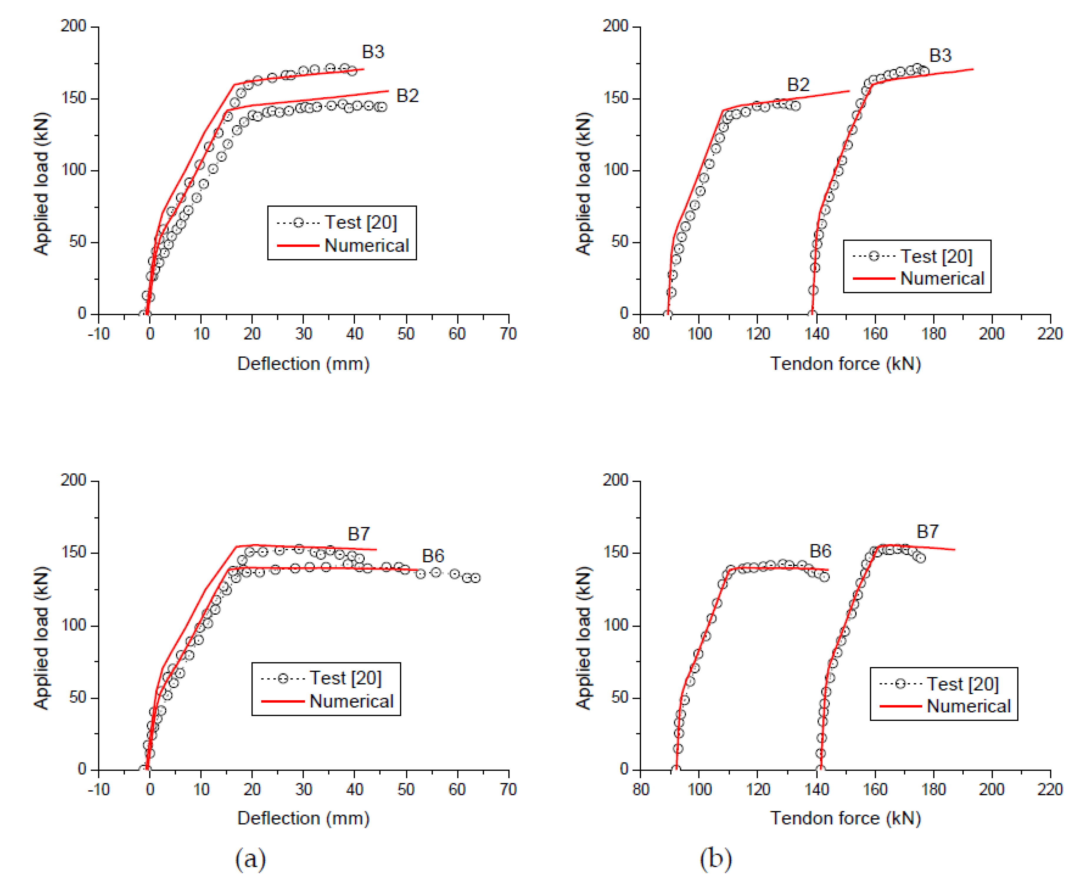
2.2. Verification with Experimental Results

Bennitz et al. [20] conducted a series of laboratory tests to investigate the flexural behavior of PCBs with external CFRP tendons. The main test variables were the tendon eccentricity, effective prestress, and deviator arrangement. Four of the beams (B2, B3, B6, and B7) were analyzed herein to verify the proposed model. The beams were of T-shaped section, simply supported over a span of 3.0 m, and were under third-point loading up to failure, as shown in Figure 3. The beams were post-tensioned with two horizontal straight external CFRP tendons (8 mm in diameter each) with an initial effective depth of 200 mm. Beams B2 and B3 were provided with one deviator at the midspan, while Beams B6 and B7 had no deviator. The bottom reinforcement consisted of two deformed steel rebars, each having 16 mm in diameter, while the top reinforcement consisted of four deformed steel rebars, each having 8 mm in diameter. The material parameters of the specimens are given in Table 1.
According to the proposed analysis, crushing failure occurs at the midspan, after significant yielding of tensile rebars (formation of a plastic hinge with sufficient rotation). This failure mode is consistent with the experimental observation. The load-displacement curves and the tendon force’s development generated by the proposed analysis are compared to the experimental data in Figure 4. It was observed that although the proposed analysis overestimated the tendon force at ultimate in some specimens (B2, B3, and B7), the numerical results were generally in satisfactory agreement with the experimental ones over the entire ranges of loading.

3. Numerical Evaluation

A simply supported PCB with external tendons draped at two deviators, as shown in Figure 5, is used herein for the study. The depths of external tendons at the end supports and deviators were 300 and 500 mm, respectively. The prestressing tendons were 1000 mm2 in area, made of CFRP composites having the tensile strength of 1840 MPa and the modulus of elasticity of 147 GPa. The initial prestress prior to prestress transfer was 1104 MPa, namely 60% of the tensile strength. The area of tensile rebars, Ar, varied from 360 to 3560 mm2. Thus, the value of ρr (ratio of tensile rebars) ranged from 0.22% to 2.16%, where ρr = Ar/(bdr) in which b is the cross-sectional width; and dr is the depth of tensile rebars. The area of compressive rebars was 360 mm2. Three types of bonded rebars were considered, namely, steel, CFRP, and GFRP. The mechanical properties of the rebars are given in Table 2. The concrete strength fck is 60 MPa.

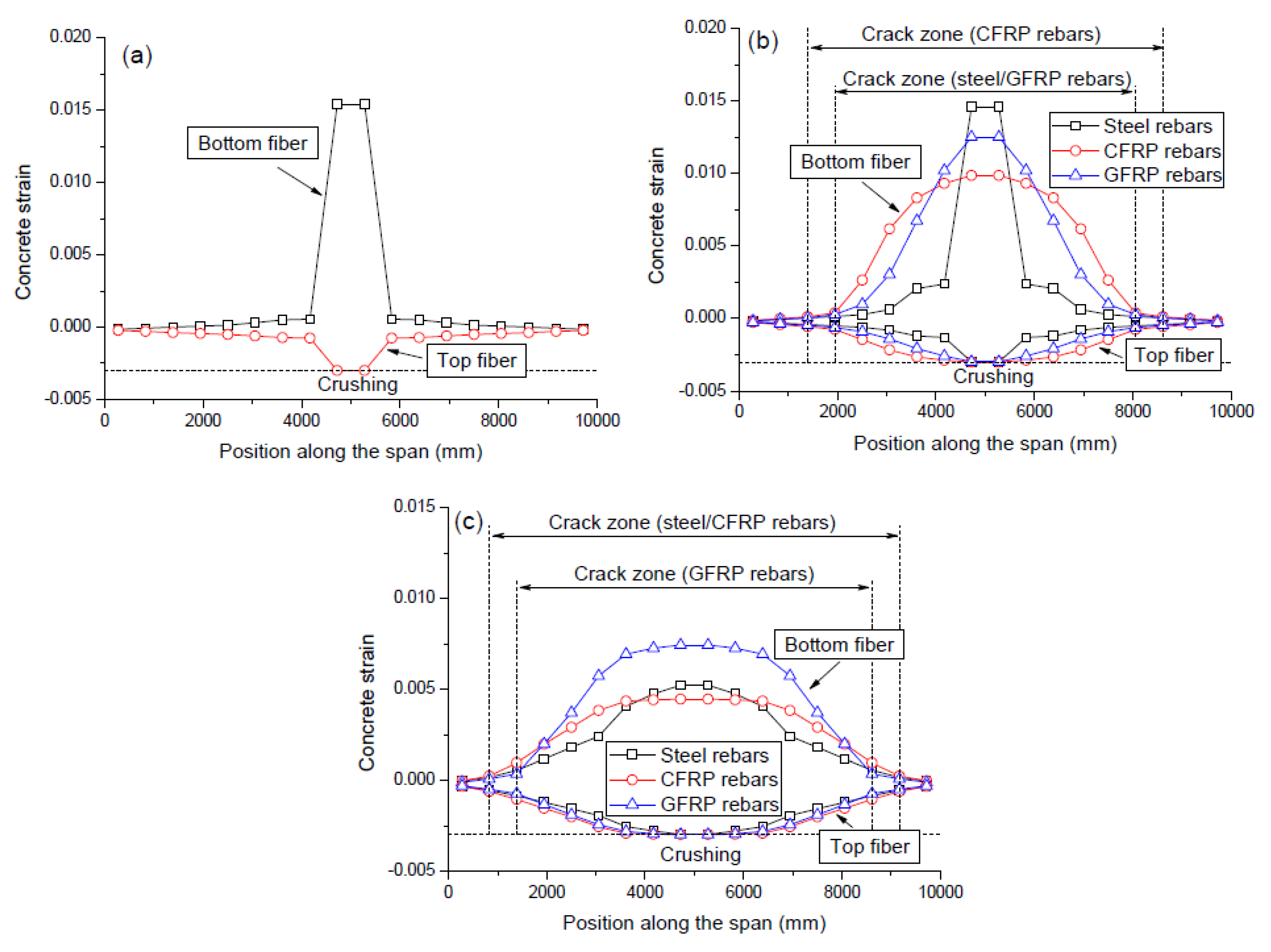
3.1. Failure and Cracking Modes

Figure 6 shows the ultimate strain distribution in the top and bottom fibers of the beams with different ρr levels. The failure and cracking modes can be seen in the graphs of this figure. Failure of all the investigated beams occurs due to concrete crushing at midspan when the specified ultimate compressive strain of 0.003 is reached. For a beam with no rebars (ρr = 0.0%), the noncritical sections were still far below their ultimate strain capacity at failure. When a minimum content of tensile rebars was provided (ρr = 0.22%), the exploitation of noncritical sections was improved. Such improvement is pronounced for FRP (especially CFRP) rebars and relatively not so notable for steel rebars. However, at a high ρr level of 2.16%, the exploitation of noncritical sections for steel rebars is nearly comparable to that for FRP rebars. At failure, both FRP tendons and rebars did not reach their rupture strength while the tensile steel rebars had yielded.
Cracks of concrete occur once the tensile strain reaches its cracking strain. Over the cracking zone, the crack width may be represented by the ultimate tensile strain. In the case for ρr = 0%, there appears a huge tensile strain at the midspan against marginal ones over the other zones. This indicates an unfavorable crack mode, i.e., the beam has only one large crack at the midspan, and the concrete over other zones is nearly uncracked. By providing a minimum content of tensile rebars (ρr = 0.22%), the crack mode was substantially improved, i.e., the crack width at the midspan was reduced, and more cracks occurred at the noncritical zones. The use of CFRP rebars is more effective than the use of GFRP or steel rebars to improve the crack mode. At a high ρr level of 2.16%, the crack modes for the beams with CFRP and steel rebars are similar, while GFRP rebars lead to smaller crack zone and larger crack width over the flexural span than steel rebars.

3.2. Tendon Stress Development

Figure 7a shows the stress increase in external tendons versus midspan deflection curves for the beams with different types of rebars (ρr = 1.19%). There was a roughly linear relationship between the tendon stress and the deflection. The slopes for the beams with steel, CFRP, and GFRP rebars were 2.12, 2.2, and 2.46 MPa/mm, respectively. Figure 7b shows the stress increase in external tendons with the applied load. The beams with FRP rebars exhibited bilinear behavior with a turning point due to concrete cracking, while the beam with steel rebars exhibit trilinear behavior with turning points due to concrete cracking and steel yielding, respectively. Since the elastic behavior is dominated by concrete, the type of rebars appears to have practically no influence on the tendon stress evolution in the elastic range of loading. Beyond cracking, GFRP rebars develop substantially lower rebar stress because of the smaller elastic modulus and, therefore, a higher stress increase in external tendons is required at a given load level to satisfy the force equilibrium when compared to CFRP or steel rebars.
The variations of the ultimate stress increment in external tendons (Δσp) and the ultimate load (Pu) with the ρr level are illustrated in Figure 7c,d, respectively. As ρr increases, the value of Δσp quickly decreases for the beams with CFRP rebars while it decreases slightly for the beams with GFRP or steel rebars. As expected, GFRP rebars resulted in substantially higher (around 70% higher) Δσp than steel rebars. At ρr = 0.22%, the Δσp ratio between the beams with CFRP and steel rebars was as high as 1.73, attributed to the fact that CFRP rebars led to much better exploitation of noncritical sections than steel rebars. This ratio was reduced to 1.12 at ρr = 2.16%. This could be explained by the comparable exploitation of noncritical sections of the beams with CFRP and steel rebars, as mentioned in the previous section. The ultimate load is dependent upon the ultimate stresses in external tendons and tensile rebars. Due to higher reinforcement stresses at ultimate, CFRP rebars led to substantially higher (37.1% higher) ultimate load than steel rebars at ρr = 0.22%. The difference tends to decrease with increasing ρr due to the reduced difference between reinforcement stresses in the beams with CFRP and steel rebars. At a low ρr level of 0.22%, GFRP rebars lead to a slightly higher ultimate load than steel rebars. As ρr increases, the increase in ultimate load for the beams with GFRP rebars is slower than that for the beams with steel rebars. As a result, when ρr increases to a level greater than 0.77%, the ultimate load for the beams with GFRP rebars turns to be lower than that for the beams with steel rebars.

3.3. Deformation Behavior

The moment-curvature and load-deflection curves for the beams with different types of rebars (ρr = 1.19%) are shown in Figure 8a,b, respectively. In the precracking stage, the effect of rebars on the response characteristics is negligible due to slight stress increments in rebars. The responses for the beams with FRP and steel rebars differ after cracking because the rebar contribution becomes increasingly important. The reduction in flexural stiffness due to cracking is highly dependent on the rebar modulus of elasticity, i.e., the higher the rebar modulus of elasticity, the less the reduction in member stiffness. Therefore, at a given load level, GFRP rebars lead to higher post cracking deformation than CFRP or steel rebars. The post cracking deformation for the beams with FRP rebars develops linearly until failure. For the beam with steel rebars, a significant further reduction in flexural stiffness occurs on steel yielding.
Figure 8c,d illustrates the variation of ultimate midspan curvature (κu) and deflection (Δu) with varying ρr, respectively. It is seen in Figure 8c that the value of κu decreases as ρr increases. GFRP rebars mobilize a smaller κu at low ρr levels whereas a larger κu at high ρr levels in comparison with steel rebars. CFRP rebars mobilize lower κu than steel rebars; the difference is substantial at low ρr levels but reduced with increasing ρr. It was noted that the above observation was similar to the effect of rebars on the crack width (represented by the ultimate concrete tensile strain), as discussed previously. This was because the ultimate curvature was directly proportional to the ultimate concrete tensile strain in terms of the plane section hypothesis. As shown in Figure 8d, GFRP rebars register substantially higher Δu than steel rebars because of a significantly lower modulus of elasticity. CFRP rebars register considerably higher Δu than steel rebars at low ρr levels, while the difference is reduced with increasing ρr. This could also be attributed to the rebar effect on the exploitation of noncritical sections, as explained previously.

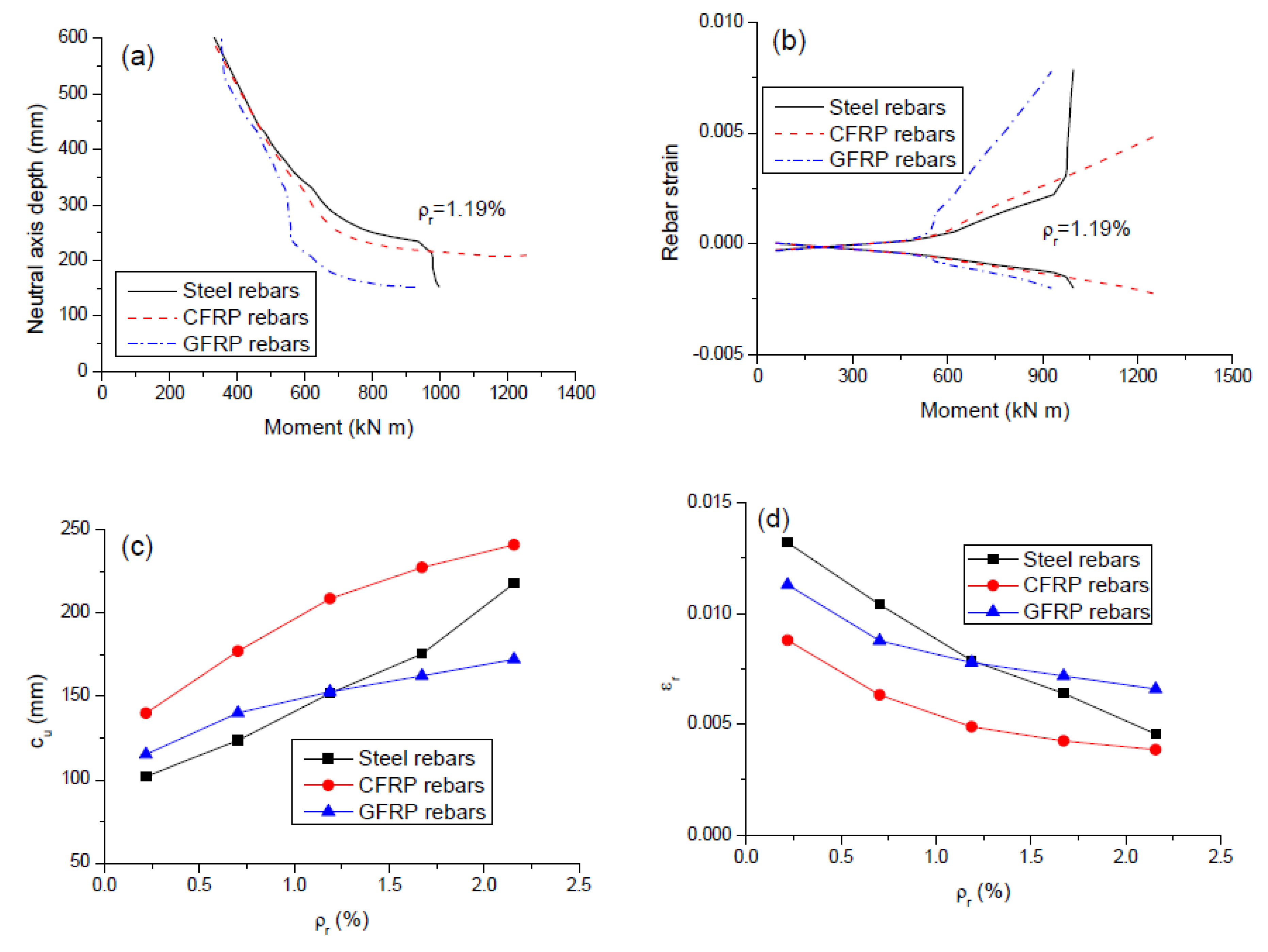
3.4. Neutral Axis Depth and Rebar Strain

Since the neutral axis depth and rebar strain are key parameters describing flexural ductility [33], it is important to understand their behavior well. The movement of the neutral axis, after it rises to the midspan section’s bottom fiber, with the moment for the beams with different types of rebars (ρr = 1.19%) is illustrated in Figure 9a. For the beams with FRP rebars, the neutral axis shifts rapidly with the increasing moment, and then the shift gradually slows down. Similar behavior was observed for the beam with steel rebars until yielding. After that, a fast movement of the neutral axis is resumed due to steel yielding. Figure 9b shows the strain development in FRP and steel rebars with the bending moment (ρr = 1.19%). The behavior for the beam with steel rebars exhibited three stages with transitions caused by cracking and yielding, respectively. Two-stage behavior was observed for the beams with FRP rebars because of the lack of yielding. Due to a lower modulus of elasticity, GFRP rebars exhibited a significantly faster increase in strain after cracking but a slower stress development when compared to steel or CFRP rebars.
Figure 9c,d shows the variation of neutral axis depth (cu) and tensile bar strain at ultimate (εr) with varying ρr, respectively. Comparing these graphs to the graph of Figure 8c, it is seen that the effect of rebars on κu is opposite to that on cu while coincident to that on εr. Their theoretical relationships can explain this observation. According to the plane section hypothesis, cu and εr are related to κu by: c u = ε u / κ u ; ε r = κ u ( d r c u ) = κ u d r ε u , where dr is the depth of tensile rebars, equal to 550 mm; εu is the ultimate concrete compressive strain, equal to 0.003. Because of a smaller value of κu, CFRP rebars mobilize a higher cu value and a lower εr value than steel rebars. Likewise, the values of cu and εr mobilized by GFRP rebars could be higher or lower than those by steel rebars, depending on the ρr level.

4. Analytical Modeling

4.1. Existing Models Using Combined Reinforcing Index for Prediction of Ultimate Stress in Unbonded Tendons
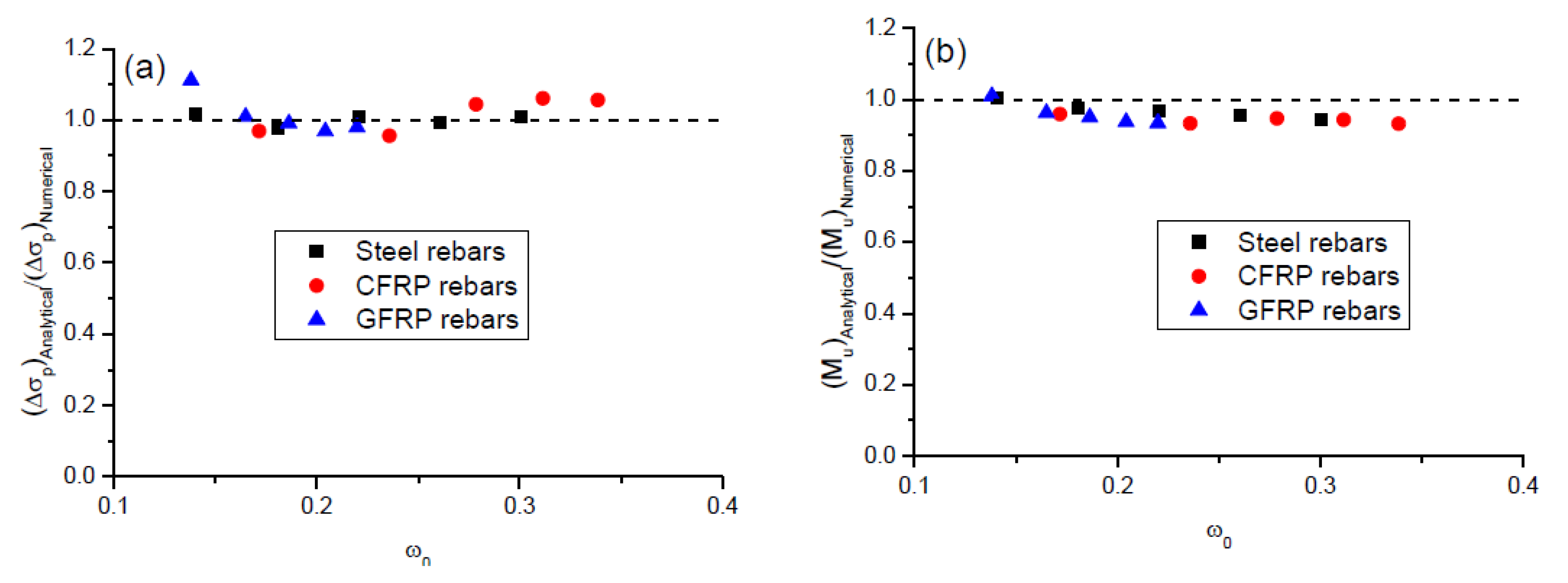
Owing to strain incompatibility, the stress in external or unbonded tendons is member-dependent. The quantification of the tendon stress is a key task in design practice. The combined reinforcing index is considered one of the best parameters used for calculating the tendon stress, as this parameter involves several important factors, including the tendon area and depth, effective prestress, rebar area, and concrete strength. The combined reinforcing index for the beams with steel rebars is defined by
ω 0 = A p σ p e + A r f y b d p f c k
where dp is the tendon depth. At ultimate, FRP rebars often reach a stress level far below their rupture strength. Therefore, the combined reinforcing index for the beams with FRP rebars could be expressed by
ω 0 = A p σ p e + A r σ r b d p f c k
where σr is the stress in tensile rebars at ultimate.
Figure 10a shows the numerical results regarding the relationship between Δσp and ω0 for the beams with FRP and steel rebars. It is interesting to note that the variations of Δσp with varying ω0 for the beams with CFRP and GFRP rebars appear to be consistent. Since CFRP represents the highest modulus of elasticity and GFRP the lowest one amongst FRP groups, it can be concluded that the beams with different types of FRP rebars follow approximately the same Δσp-ω0 response. At a given ω0 value, the beams with FRP rebars led to substantially higher tendon stress than the beams with steel rebars. The tendon stress tends to decrease with increasing ω0, while the decrease for the beams with FRP rebars is much quicker than that for the beams with steel rebars.
By performing laboratory tests of 22 PCBs with unbonded tendons, Du and Tao [34] found an approximately linear relationship between the tendon stress and the combined reinforcing index. They recommended the following expression for calculating Δσp:
Δ σ p = 786 1920 ω 0
JGJ/T 92-93 [35] suggested the following Equation for the computation of Δσp:
Δ σ p = 500 770 ω 0
for L/dp ≤ 35; and
Δ σ p = 250 380 ω 0
for L/dp > 35.
JGJ 92-2016 [36] proposed a modification of the above Equation, which is expressed as follows:
Δ σ p = ( 240 335 ω 0 ) ( 0.45 + 5.5 h / L 0 ) L 2 L 1
where ω0 is not greater than 0.4; h is the cross-sectional depth; L0 is the span length; L1 is the tendon length between end anchorages for continuous beams, and L2 is the total length of loaded spans.
It should be noted that the above models were developed for the beams with steel rebars. To evaluate the applicability of the models, the predictions by the simplified equations against the numerical data for the beams with steel rebars are presented in Figure 10b, while those for the beams with FRP rebars are presented in Figure 10c. It was observed that, in general, the Du and Tao model and JGJ/T 92-93 are unsafe, while JGJ 92-2016 is conservative when predicting the tendon stress in the beams with steel rebars. In addition, the Du and Tao model substantially overestimates the influence of ω0. For the beams with FRP rebars, the effect of ω0 on the tendon stress is overestimated by the Du and Tao model while underestimated by JGJ/T 92-93 and JGJ 92-2016. Moreover, JGJ 92-2016 appears to be overly conservative.

4.2. Proposed Model

According to the linear fit to the numerical data of the beams with steel and FRP rebars as illustrated in Figure 11, the following Equation is proposed for predicting the stress increment in external tendons at ultimate:
Δ σ p = 303 220 ω 0
for the beams with steel rebars; and
Δ σ p = 626 1032 ω 0
for the beams with FRP rebars.
It is worth mentioning that at given cross-sectional and material properties, the value of ω0 in the beams with steel rebars is known (see Equation (1)), whereas that in the beams FRP rebars is unknown (see Equation (2)). Consequently, the value of Δσp in the beams with steel rebars can be calculated directly by using Equation (7), while the computation of Δσp in the beams with FRP rebars needs to combine Equation (8) with the section equilibrium equation.
The axial equilibrium equation of the critical section of the beams with steel rebars is
0.85 f c k b β 1 c u = A p ( σ p e + Δ σ p ) + A r f y A r f y
where β1 is the stress-block factor for concrete, taken equal to 0.85; Ar and A r are the area of tensile and compressive rebars, respectively. Substituting Equation (7) into Equation (9) results in
c u = A p ( σ p e + 303 220 ω 0 ) + A r f y A r f y 0.85 f c k b β 1
Hence, the flexural strength for the beams with steel rebars is calculated from
M u = A p ( σ p e + Δ σ p ) d e + A r f y d r A r f y d r 0.85 f c k b ( β 1 c u ) 2 / 2
where dr and d r are the effective depth of tensile and compressive rebars, respectively; de is the effective depth at ultimate of external tendons. The value of de can be obtained by
d e = R d d p
where Rd is the depth reduction factor as a result of second-order effects of externally PCBs, which may be calculated from
R d = 1.14 0.005 ( L / d p ) 0.19 ( S d / L ) 1.0
for center-point loading; and
R d = 1.25 0.01 ( L / d p ) 0.38 ( S d / L ) 1.0
for third-point loading.
On the other hand, the axial equilibrium of the critical section of the beams with FRP rebars is given by
0.85 f c k b β 1 c u = A p ( σ p e + Δ σ p ) + A r σ r A r σ r
where
σ r = E f ε u ( d r c u 1 )
σ r = E f ε u ( 1 d r c u )
where Ef and E f are the elastic modulus of tensile and compressive FRP rebars, respectively; εu is taken equal to 0.003. Combining Equations (2), (8), (16), and (17) with Equation (15) leads to
c u = B + B 2 4 A C 2 A
where
A = 0.85 f c k b β 1 B = A r E f ε u ( 1 1032 ρ p / f c k ) + A r E f ε u A p ( σ p e + 626 1032 ω p ) C = A r E f ε u d r ( 1 1032 ρ p / f c k ) A r E f ε u d r
where
ρ p = A p b d p
ω p = A p σ p e b d p f c k
Hence, the flexural strength for the beams with FRP rebars is obtained by
M u = A p ( σ p e + Δ σ p ) d e + A r σ r d r A r σ r d r 0.85 f c k b ( β 1 c u ) 2 / 2
A comparison of the ultimate tendon stress increment and flexural strength predicted by the proposed analytical model with the numerical results for the beams with steel and FRP rebars is presented in Table 3 and Figure 12. It is seen that there is a good agreement between the analytical predictions and numerical data. The mean discrepancy for the ultimate tendon stress increment is 1.03% with a standard deviation of 4.08%, while that for the ultimate moment is −4.33% with a standard deviation of 2.32%.

5. Conclusions

A numerical and analytical study was conducted on simply supported PCBs with external CFRP tendons, aimed at identifying the effect of providing FRP bonded rebars instead of steel ones. Based on the results of the study, the following conclusions can be drawn:
  • FRP (especially CFRP) rebars lead to better exploitation of noncritical sections than steel rebars, particularly notable at a low ρr level. The crack mode is improved by providing a minimum amount of rebars, while the improvement is more effective using CFRP rebars than using GFRP or steel rebars.
  • CFRP rebars lead to larger ultimate load and neutral axis depth but smaller ultimate curvature and tensile rebar strain than steel rebars. Such values registered by GFRP rebars could be larger or smaller than those by steel rebars, depending on the ρr level.
  • GFRP rebars mobilize substantially higher ultimate deflection and tendon stress increment than steel rebars. CFRP rebars lead to similar observation at a low ρr level, while the difference between the values for the beams with CFRP and steel rebars diminishes as ρr increases.
  • Both JGJ/T 92-93 and JGJ 92-2016 underestimated the influence of combined reinforcing index on external tendons’ stress at ultimate in the beams with FRP rebars. Moreover, JGJ 92-2016 appears to be overly conservative for predicting the ultimate tendon stress.
  • An analytical model was proposed to predict the tendon stress at ultimate and flexural strength in externally PCBs with steel and FRP rebars. The model predictions are in good agreement with the numerical results.
The present study is limited to simply supported conditions. Further studies on the use of FRP rebars instead of steel ones in continuous PCBs with external tendons shall be performed in the future.

Author Contributions

Conceptualization, M.P. and T.L.; Methodology, M.P.; Software, T.L.; Validation, Z.L.; Formal Analysis, Z.L.; Investigation, Z.L. and M.P.; Resources, T.L.; Data Curation, Z.L.; Writing—Original Draft Preparation, M.P.; Writing—Review & Editing, Z.L.; Visualization, Z.L.; Supervision, T.L. All authors have read and agreed to the published version of the manuscript.

Funding

This research received no external funding.

Conflicts of Interest

The authors declare no conflict of interest.

References

  1. Ahmad, S. Reinforcement corrosion in concrete structures, its monitoring and service life prediction—A review. Cem. Concr. Compos. 2003, 25, 459–471. [Google Scholar]
  2. Lou, T.; Karavasilis, T.L. Numerical evaluation of prestressed steel-concrete composite girders with external FRP or steel tendons. J. Constr. Steel Res. 2019, 162, 105698. [Google Scholar]
  3. Lou, T.; Peng, C.; Karavasilis, T.L.; Min, D.; Sun, W. Moment redistribution versus neutral axis depth in continuous PSC beams with external CFRP tendons. Eng. Struct. 2020, 209, 109927. [Google Scholar]
  4. Sun, W.; Jirsa, J.O.; Ghannoum, W.M. Behavior of anchored carbon fiber-reinforced polymer strips used for strengthening concrete structures. ACI Mater. J. 2016, 113, 163–172. [Google Scholar]
  5. Sun, W.; He, T.; Wang, X.; Zhang, J.; Lou, T. Developing an anchored near-surface mounted (NSM ) FRP system for fuller use of FRP material with less epoxy filler. Compos. Struct. 2019, 226, 111251. [Google Scholar]
  6. Mostofinejad, D.; Hosseini, S.M.; Tehrani, B.N.; Eftekhar, M.R.; Dyari, M. Innovative warp and woof strap (WWS) method to anchor the FRP sheets in strengthened concrete beams. Constr. Build. Mater. 2019, 218, 351–364. [Google Scholar]
  7. Wang, L.; Kawaguchi, K.; Xu, J.; Han, Q. Effects of transverse constraints on the longitudinal compressive strength of unidirectional CFRP pultruded plates and rods. Compos. Struct. 2019, 207, 740–751. [Google Scholar]
  8. Xu, J.; Wang, W.; Han, Q.; Liu, X. Damage pattern recognition and damage evolution analysis of unidirectional CFRP tendons under tensile loading using acoustic emission technology. Compos. Struct. 2020, 238, 111948. [Google Scholar]
  9. ACI committee 440. Guide for the Design and Construction of Structural Concrete Reinforced with FRP Bars; ACI 440.1R-06: Farmington Hills, MI, USA, 2006. [Google Scholar]
  10. ACI committee 440. Prestressing Concrete Structures with FRP Tendons; ACI 440.4R-04: Farmington Hills, MI, USA, 2004. [Google Scholar]
  11. El Refai, A.; Abed, F.; Altalmas, A. Bond durability of basalt fiber–reinforced polymer bars embedded in concrete under direct pullout conditions. ASCE J. Compos. Constr. 2015, 19, 04014078. [Google Scholar]
  12. Altalmas, A.; El Refai, A.; Abed, F. Bond degradation of basalt fiber-reinforced polymer (BFRP) bars exposed to accelerated aging conditions. Constr. Build. Mater. 2015, 81, 162–171. [Google Scholar]
  13. Al-Tamimi, A.; Abed, F.H.; Al-Rahmani, A. Effects of harsh environmental exposures on the bond capacity between concrete and GFRP reinforcing bars. Adv. Concr. Constr. 2014, 2, 1–11. [Google Scholar]
  14. Grace, N.F.; Abdel-Sayed, G. Behavior of externally draped CFRP tendons in prestressed concrete bridges. PCI J. 1998, 43, 88–101. [Google Scholar]
  15. Ghallab, A.; Beeby, A.W. Factors affecting the external prestressing stress in externally strengthened prestressed concrete beams. Cem. Concr. Compos. 2005, 27, 945–957. [Google Scholar]
  16. Abdel Aziz, M.; Abdel-Sayed, G.; Ghrib, F.; Grace, N.F.; Madugula, M.K.S. Analysis of concrete beams prestressed and post-tensioned with externally unbonded carbon fiber reinforced polymer tendons. Can. J. Civ. Eng. 2005, 31, 1138–1151. [Google Scholar]
  17. Wang, X.; Shi, J.; Wu, G.; Yang, L.; Wu, Z. Effectiveness of basalt FRP tendons for strengthening of RC beams through the external prestressing technique. Eng. Struct. 2015, 101, 34–44. [Google Scholar]
  18. Zhu, H.; Dong, Z.; Wu, G.; Chen, H.; Li, J.; Liu, Y. Experimental Evaluation of Bent FRP Tendons for Strengthening by External Prestressing. ASCE J. Compos. Constr. 2017, 21, 04017032. [Google Scholar]
  19. Lou, T.; Lopes, S.M.R.; Lopes, A.V. Numerical analysis of behaviour of concrete beams with external FRP tendons. Constr. Build. Mater. 2012, 35, 970–978. [Google Scholar]
  20. Bennitz, A.; Schmidt, J.W.; Nilimaa, J.; Taljsten, B.; Goltermann, P.; Ravn, D.L. Reinforced concrete T-beams externally prestressed with unbonded carbon fiber-reinforced polymer tendons. ACI Struct. J. 2012, 109, 521–530. [Google Scholar]
  21. ACI Committee 318. Building Code Requirements for Structural Concrete (ACI 318-14) and Commentary (ACI 318R-14); American Concrete Institute: Farmington Hills, MI, USA, 2014. [Google Scholar]
  22. Abed, F.; Oucif, C.; Awera, Y.; Mhanna, H.H.; Alkhraisha, H. FE modeling of concrete beams and columns reinforced with FRP composites. Def. Technol. 2020. [Google Scholar] [CrossRef]
  23. Abed, F.; El Refai, A.; Abdalla, S. Experimental and finite element investigation of the shear performance of BFRP-RC short beams. Structures 2019, 20, 689–701. [Google Scholar]
  24. Al-Rahmani, A.; Abed, F.H. Numerical investigation of hybrid FRP reinforced beams. In Proceedings of the 5th International Conference on Modeling, Simulation and Applied Optimization (ICMSAO), Hammamet, Tunisia, 28–30 April 2013; pp. 1–6. [Google Scholar] [CrossRef]
  25. Ju, M.; Park, Y.; Park, C. Cracking control comparison in the specifications of serviceability in cracking for FRP reinforced concrete beams. Compos. Struct. 2018, 182, 674–684. [Google Scholar]
  26. Alam, M.S.; Hussein, A. Relationship between the shear capacity and the flexural cracking load of FRP reinforced concrete beams. Constr. Build. Mater. 2017, 154, 819–828. [Google Scholar]
  27. Barris, C.; Torres, L.; Vilanova, I.; Mias, C.; Llorens, M. Experimental study on crack width and crack spacing for Glass-FRP reinforced concrete beams. Eng. Struct. 2017, 131, 231–242. [Google Scholar]
  28. Dundar, C.; Tanrikulu, A.K.; Frosch, R.J. Prediction of load-deflection behavior of multi-span FRP and steel reinforced concrete beams. Compos. Struct. 2015, 132, 680–693. [Google Scholar]
  29. Lou, T.; Lopes, S.M.R.; Lopes, A.V. Neutral axis depth and moment redistribution in FRP and steel reinforced concrete continuous beams. Compos. Part B Eng. 2015, 70, 44–52. [Google Scholar]
  30. Mahroug, M.E.M.; Ashour, A.F.; Lam, D. Experimental response and code modelling of continuous concrete slabs reinforced with BFRP bars. Compos. Struct. 2014, 107, 664–674. [Google Scholar]
  31. Lou, T.; Xiang, Y. Finite element modeling of concrete beams prestressed with external tendons. Eng. Struct. 2006, 28, 1919–1926. [Google Scholar]
  32. CEN. Eurocode 2: Design of Concrete Structures—Part 1-1: General Rules and Rules for Buildings. EN 1992-1-1; European Committee for Standardization: Brussels, Belgium, 2004. [Google Scholar]
  33. Bernardo, L.; Nepomuceno, M.; Pinto, H. Neutral axis depth versus ductility and plastic rotation capacity on bending in lightweight-aggregate concrete beams. Materials 2019, 12, 3479. [Google Scholar]
  34. Du, G.C.; Tao, X.K. Ultimate stress of unbonded tendons in partially prestressed concrete beams. PCI J. 1985, 30, 72–91. [Google Scholar]
  35. JGJ/T 92-93. Technical Specification for Concrete Structures Prestressed with Unbonded Tendons; China Planning Press: Beijing, China, 1993. [Google Scholar]
  36. JGJ 92-2016. Technical Specification for Concrete Structures Prestressed with Unbonded Tendons; China Architecture & Building Press: Beijing, China, 2016. [Google Scholar]
Figure 1. Beam element, u, v, and θ are the axial, transverse displacements, and rotation, respectively.
Polymers 12 02773 g001
Figure 2. Stress–strain curves of materials. (a) concrete in compression recommended in Eurocode 2 [32]; (b) concrete in tension; (c) Fiber-reinforced polymer (FRP) tendons; (d) FRP and steel rebars.
Polymers 12 02773 g002
Figure 3. Prestressed concrete beam (PCB) specimens with external CFRP tendons [20], As, A s and Ap are the areas of tensile, compressive steel rebars and prestressing tendons, respectively.
Polymers 12 02773 g003
Figure 4. Verification with experimental results. (a) load versus midspan deflection; (b) load versus tendon force.
Polymers 12 02773 g004
Figure 5. Simply supported beam for numerical investigation, Ar and A r are the areas of tensile and compressive rebars, respectively.
Polymers 12 02773 g005
Figure 6. Concrete strain distribution at ultimate. (a) ρr = 0.0%; (b) ρr = 0.22%; (c) ρr = 2.16%.
Polymers 12 02773 g006
Figure 7. Tendon stress development for the beams with different types of rebars. (a) midspan deflection versus tendon stress increment; (b) load versus tendon stress increase; (c) variation of ultimate tendon stress increment with varying ρr; (d) variation of ultimate load with varying ρr.
Polymers 12 02773 g007
Figure 8. Deformation behavior for the beams with different types of rebars. (a) moment versus curvature at midspan; (b) load versus midspan deflection; (c) variation of ultimate curvature with varying ρr; (d) variation of ultimate deflection with varying ρr.
Polymers 12 02773 g008
Figure 9. Neutral axis depth and bar strain for different types of rebars. (a) moment versus neutral axis depth at midspan; (b) moment versus rebar strain at midspan; (c) variation of ultimate neutral axis depth with varying ρr; (d) variation of ultimate tensile rebar strain with varying ρr.
Polymers 12 02773 g009
Figure 10. Relationship between tendon stress increment and combined reinforcing index. (a) numerical results; (b) comparison between simplified models and numerical data for the beams with steel rebars; (c) comparison between simplified models and numerical data for the beams with FRP rebars.
Polymers 12 02773 g010
Figure 11. Linear fit to the numerical data. (a) beams with steel rebars; (b) beams with FRP rebars.
Polymers 12 02773 g011
Figure 12. Comparison between analytical predictions and numerical results. (a) tendon stress increment at ultimate; (b) ultimate moment.
Polymers 12 02773 g012
Table 1. Material parameters for specimens [20].
BeamSteel RebarsFRP TendonsConcrete
As (mm2)fy (MPa)Es (GPa) A s
(mm2)
f y
(MPa)
E s
(GPa)
Ap (mm2)Ef (GPa)ff (MPa)σpe (MPa)fck (MPa)
B2402560172201510187100.5158279089535.2
B3402560172201510187100.51582790138233.4
B6402560172201510187100.5158279091740.6
B7402560172201510187100.51582790140735.9
Note: As, fy and Es = area, yield strength, and elastic modulus of tensile steel rebars, respectively; A s , f y and E s = area, yield strength, and elastic modulus of compressive steel rebars, respectively; Ap = tendon area; Ef and ff = elastic modulus and tensile strength of FRP composites, respectively; σpe = effective prestress.
Table 2. Mechanical properties of rebars.
RebarsTensile Strength (MPa)Yield Strength (MPa)Elastic Modulus (GPa)
Steel450450200
CFRP1840-147
GFRP750-40
Table 3. Comparison of ultimate tendon stress increment and moment predicted by the analytical model with numerical results.
Rebarsρr (%)Δσp (MPa)Mu (kN m)
AnalyticalNumericalError (%)AnalyticalNumericalError (%)
Steel0.22272.05267.601.66654.40653.120.20
0.70263.25269.05−2.15812.72831.63−2.27
1.19254.45252.440.80962.98997.08−3.42
1.67245.65246.93−0.521105.171154.67−4.29
2.16236.85234.630.951239.311315.42−5.79
CFRP0.22448.74463.02−3.09837.89874.32−4.17
0.70382.53400.19−4.411054.401129.98−6.69
1.19338.41324.234.371189.311256.83−5.37
1.67304.47287.096.051288.011366.46−5.74
2.16276.65261.865.651365.571466.04−6.85
GFRP0.22483.51435.0211.15713.43706.311.01
0.70455.67451.081.02808.85840.51−3.77
1.19433.69437.72−0.92882.11928.20−4.97
1.67415.19428.42−3.09942.271004.81−6.22
2.16399.09407.03−1.95993.581063.79−6.60
Publisher’s Note: MDPI stays neutral with regard to jurisdictional claims in published maps and institutional affiliations.

