A Numerical Investigation on Droplet Bag Breakup Behavior of Polymer Solution


Abstract
1. Introduction
2. Numerical Method
2.1. Governing Equations
2.2. The Constitutive Equations
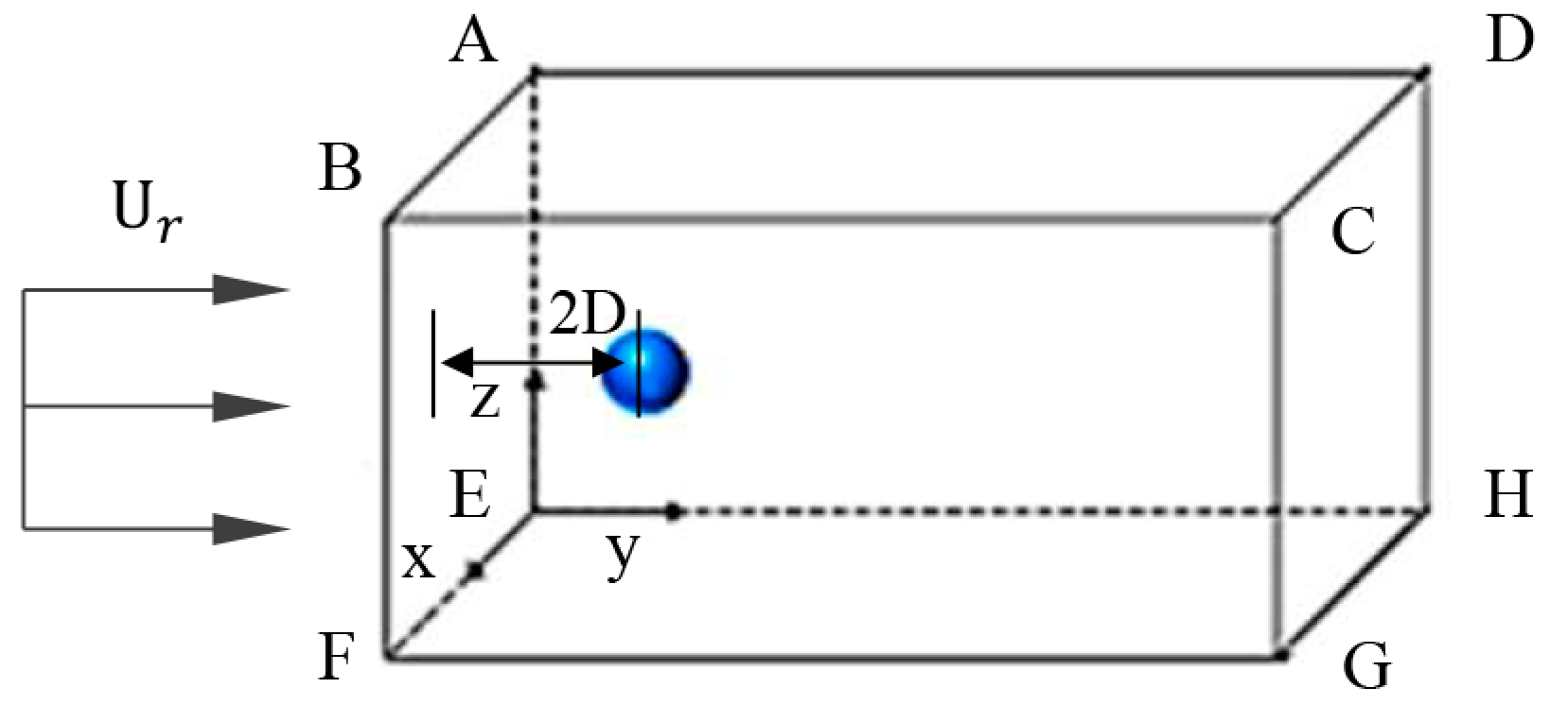
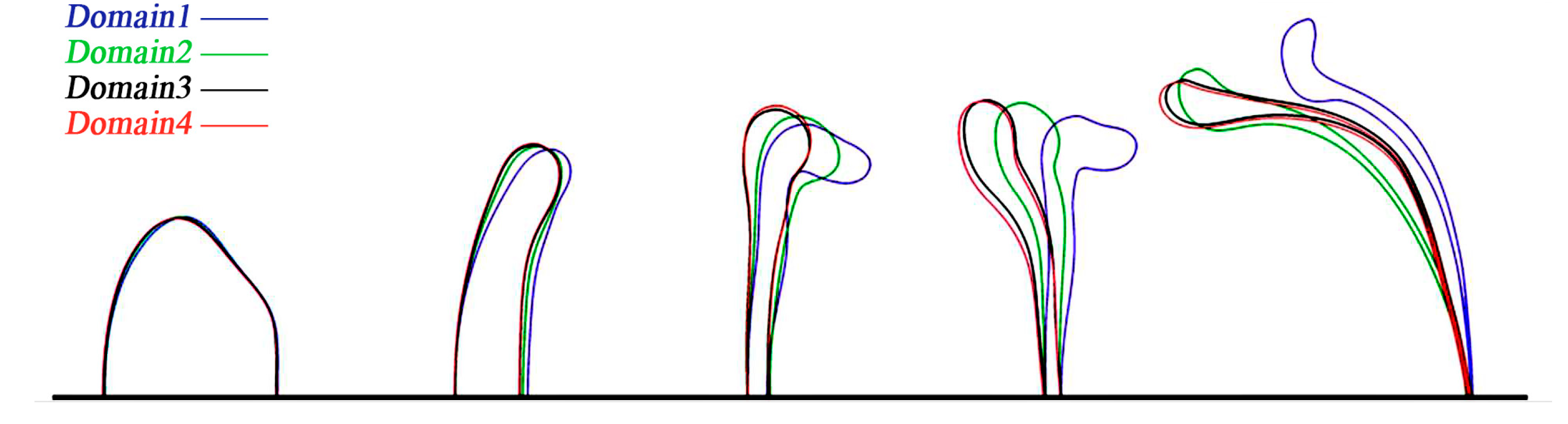
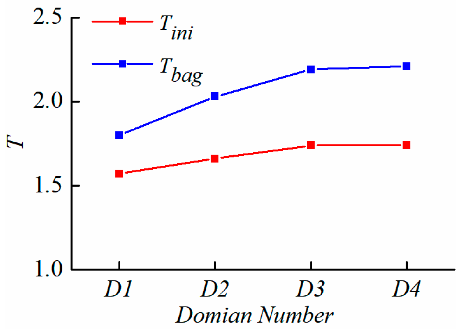
2.3. Computational Domain Setup
3. Verification
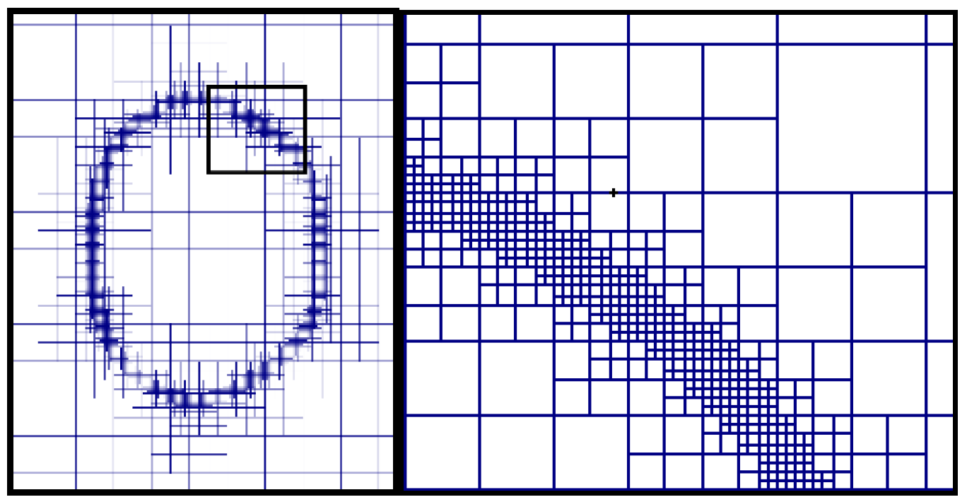
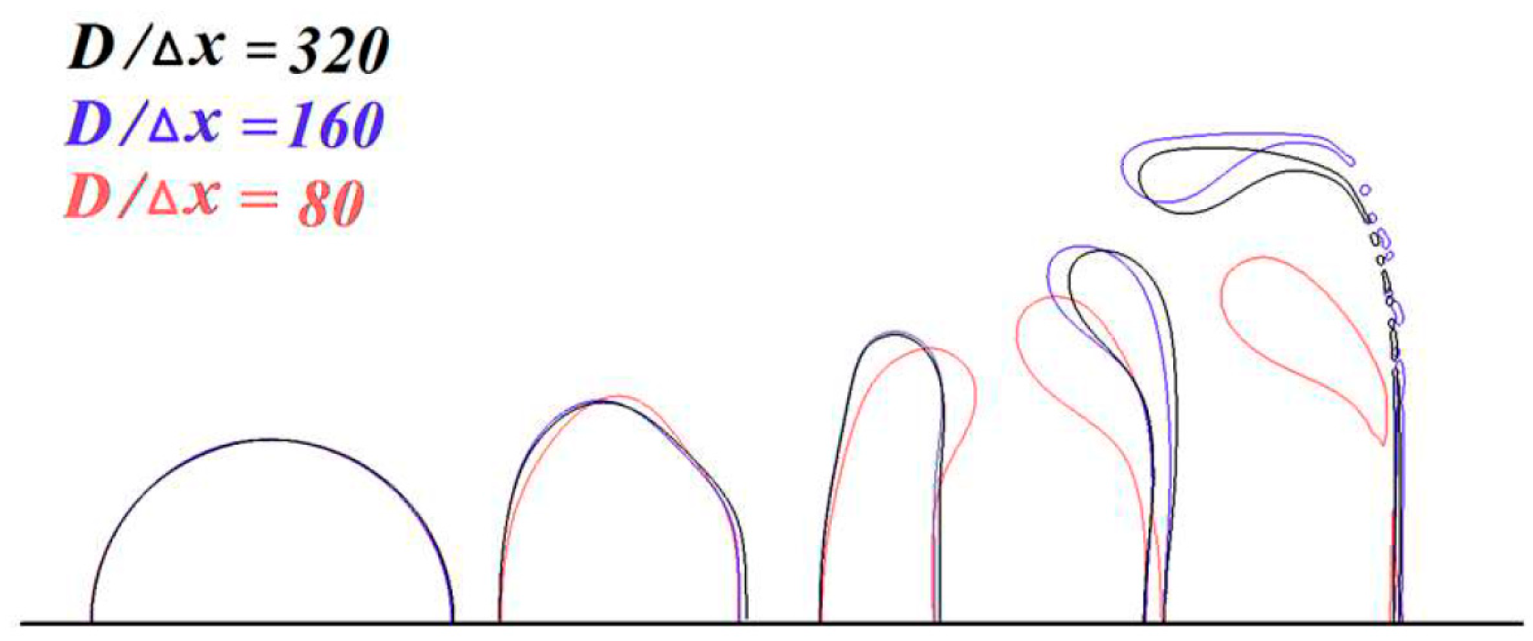
3.1. Grid Independency
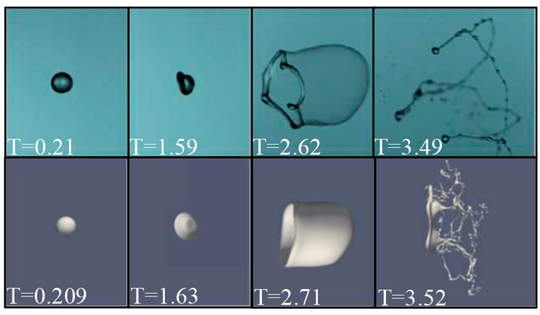
3.2. Numerical Model Verification
4. Results and Discussion
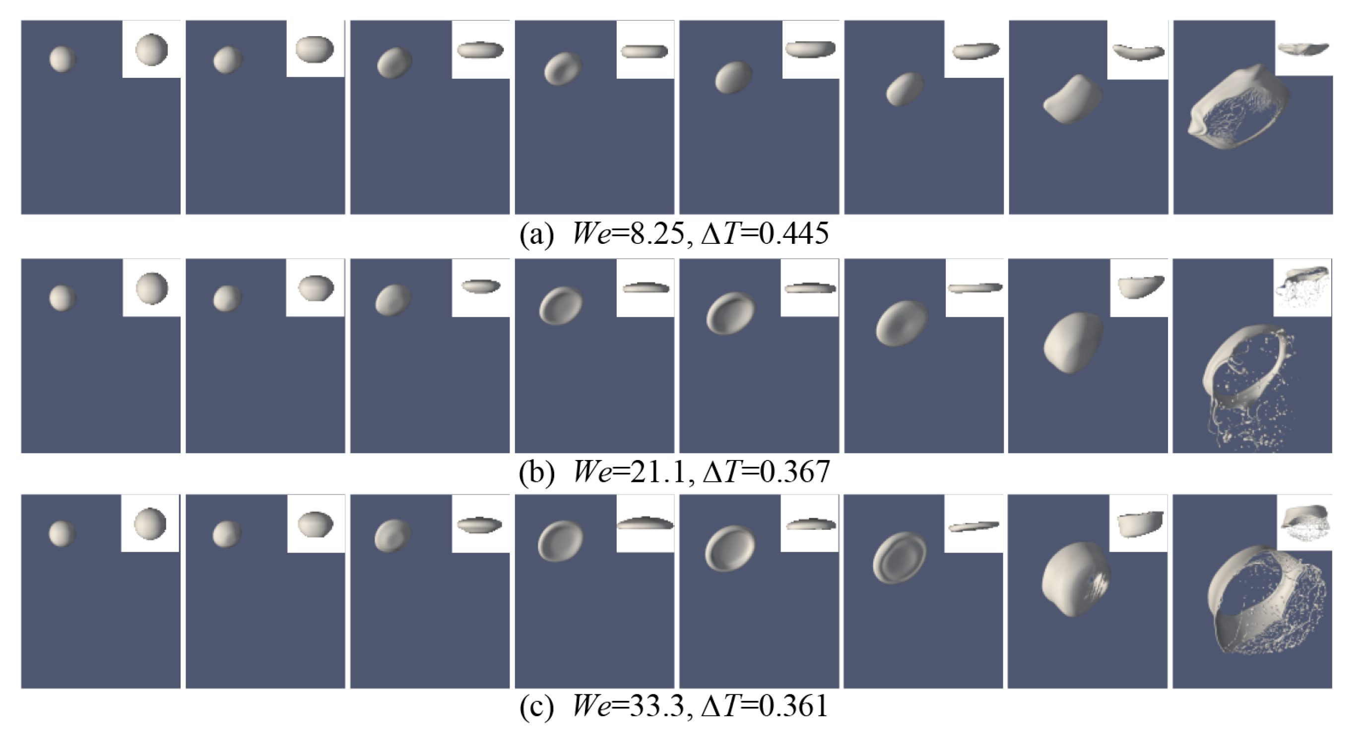
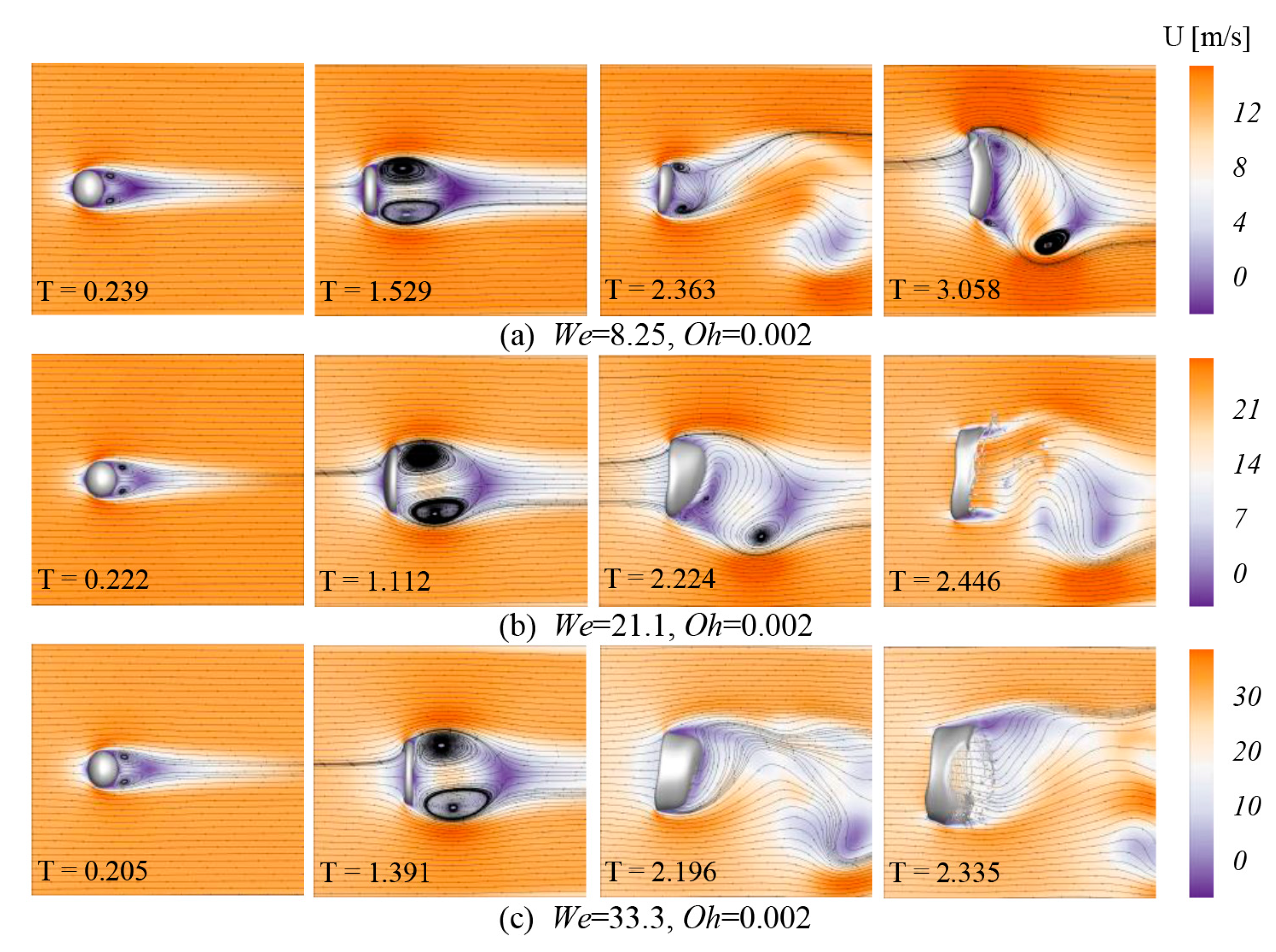
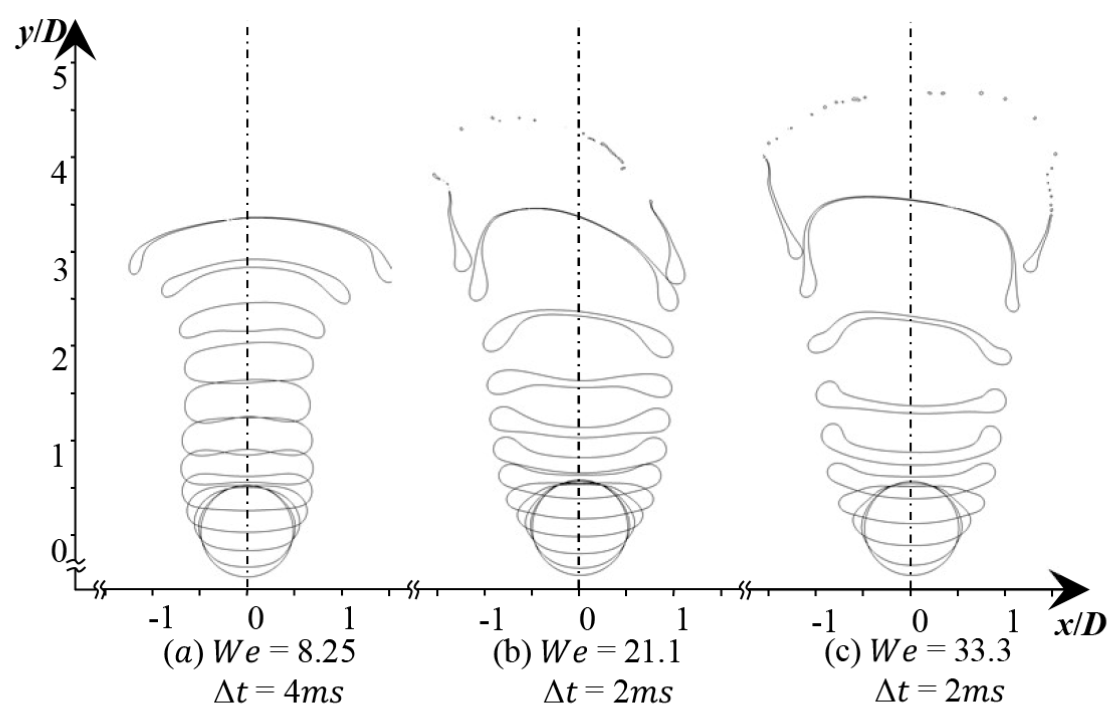
4.1. Bag Breakup Behavior and Velocity Field
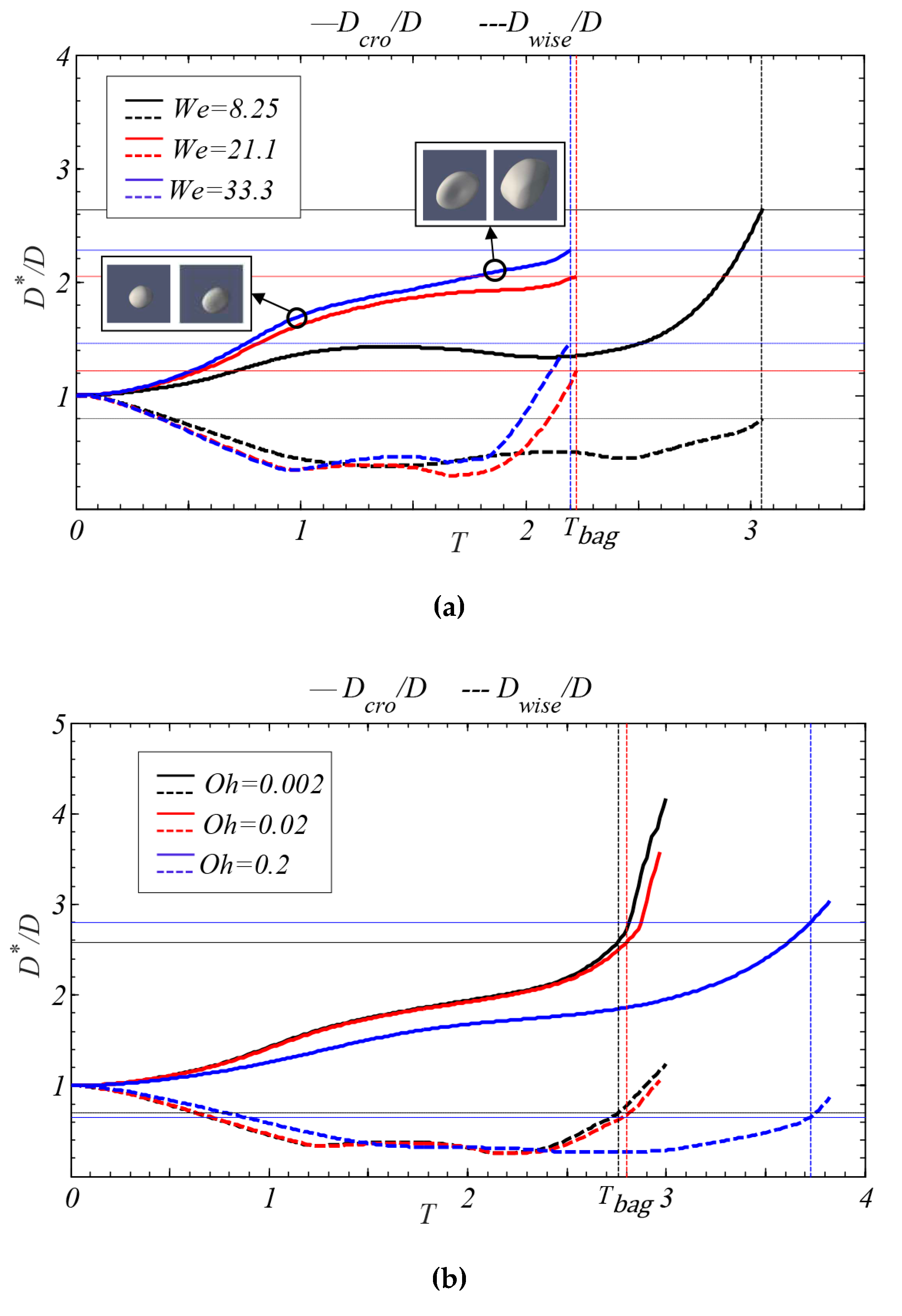
4.2. Droplet Deformation
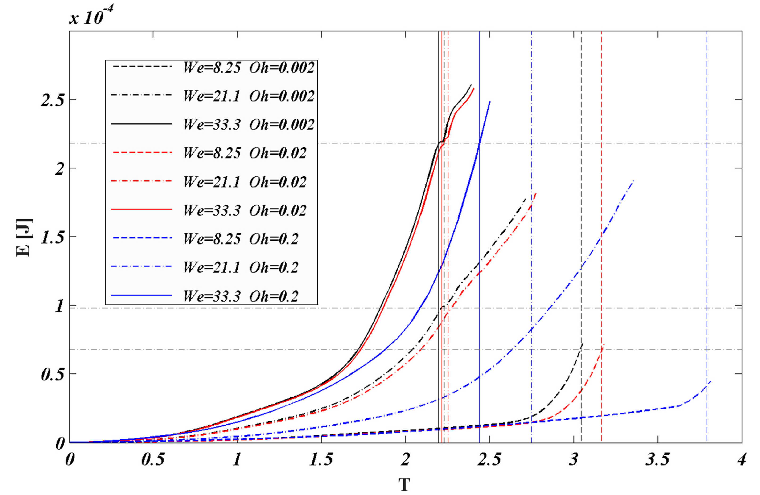
4.3. Energy Evolution
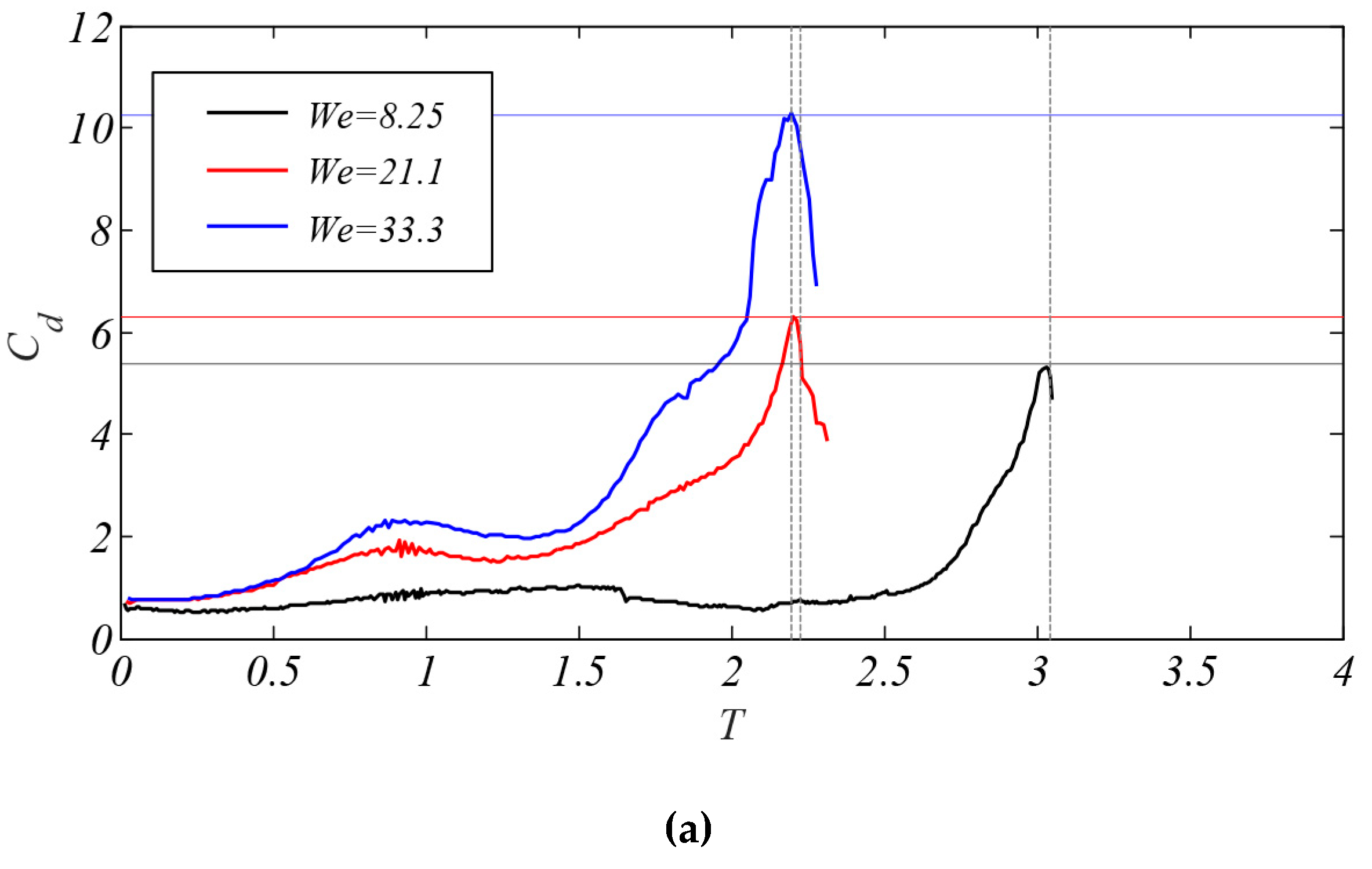
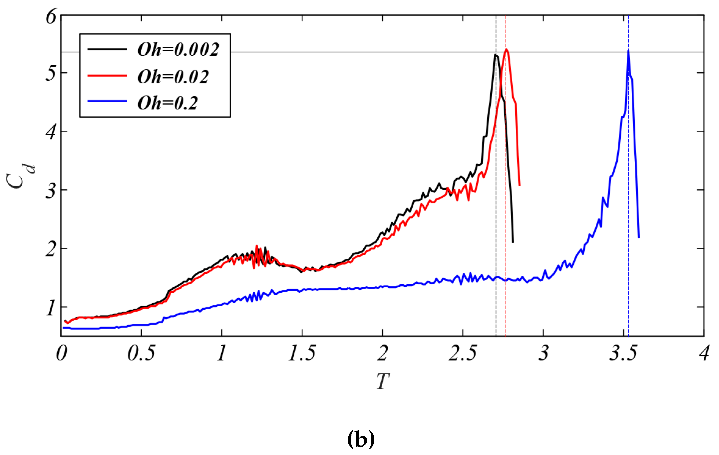
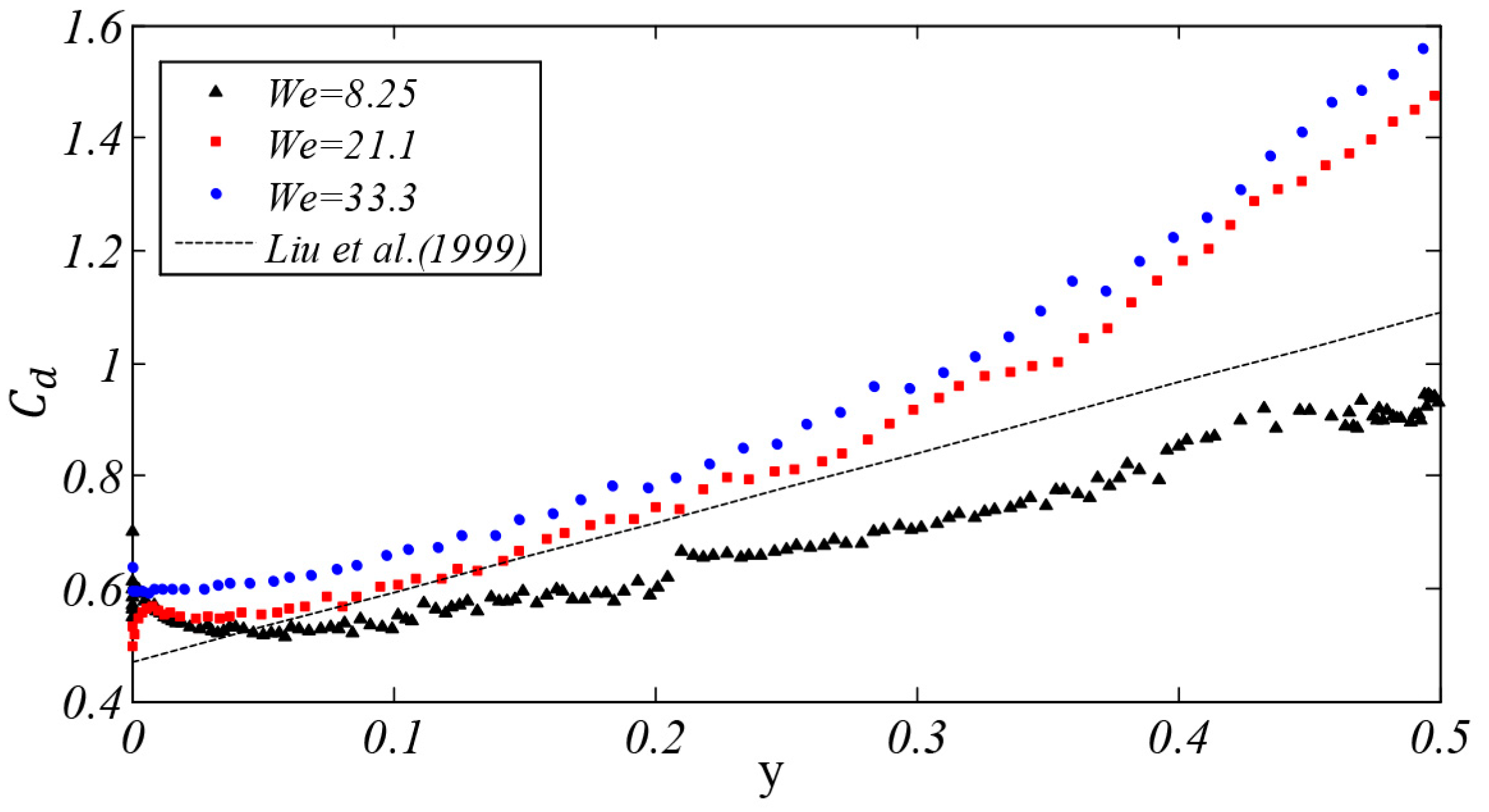
4.4. Drag Coefficient
5. Conclusions
Author Contributions
Funding
Conflicts of Interest
Abbreviations/Nomenclature
| Cd | Drag coefficient | Air velocity | |
| D | The initial diameter of liquid droplet | Liquid velocity | |
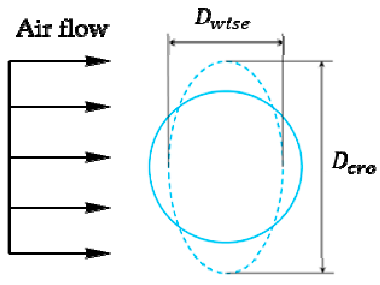
| Dcro | The cross-stream diameter | U | The velocity vector of the flow field |
| Dwise | The stream-wise diameter | The velocity of the air | |
| E | The kinetic energy | The initial relative velocity | |
| Volume surface tension | The droplet centroid velocity | ||
| The consistency coefficient | The computational grid speed | ||
| n | The rheological index | The volume of a computational cell | |
| The number of the computational cell | We | Weber number | |
| Oh | Ohnesorge number | Liquid density | |
| Oheff | Effective Ohnesorge number | Air density | |
| p | Pressure | Surface tension | |
| Re | Reynolds number | The yield stress | |
| T | Non-dimensional time | Shear rate | |
| t | Dimensional time | The phase fraction | |
| Tini | Initial breakup time | The volume fraction of the liquid phase | |
| Tbag | Bag breakup time | The velocity component | |
| Zero shear viscosity | The interface thickness | ||
| Apparent viscosity | The drop-to-ambient density ratio |
References
- Guildenbecher, D.R.; López-Rivera, C.; Sojka, P.E. Secondary atomization. Exp. Fluids 2009, 46, 371–402. [Google Scholar] [CrossRef]
- Shah, Z.; Babazadeh, H.; Kumam, P.; Shafee, A.; Thounthong, P. Numerical simulation of magnetohydrodynamic nanofluids under the influence of shape factor and thermal transport in a porous media using CVFEM. Front. Phys. 2019, 7, 164. [Google Scholar] [CrossRef]
- Shah, Z.; Mccash, L.B.; Dawar, A.; Bonyah, E. Entropy optimization in Darcy–Forchheimer MHD flow of water based copper and silver nanofluids with Joule heating and viscous dissipation effects. AIP Adv. 2020, 10, 065137. [Google Scholar] [CrossRef]
- Vo, D.D.; Shah, Z.; Sheikholeslami, M.; Shafee, A.; Nguyen, T.K. Numerical investigation of MHD nanomaterial convective migration and heat transfer within a sinusoidal porous cavity. Phys. Scr. 2019, 94, 115225. [Google Scholar] [CrossRef]
- Shah, Z.; Sheikholeslami, M.; Kumam, P. Influence of Nanoparticles inclusion into water on convective magneto hydrodynamic flow with heat transfer and entropy generation through permeable domain. Case Stud. Therm. Eng. 2020, 21, 100732. [Google Scholar] [CrossRef]
- Tang, Z.; Fang, K.; Song, Y.; Sun, F. Jetting performance of polyethylene glycol and reactive dye solutions. Polymers 2019, 11, 739. [Google Scholar] [CrossRef]
- Toschkoff, G.; Khinast, J.G. Mathematical modeling of the coating process. Int. J. Pharm. 2013, 457, 407–422. [Google Scholar] [CrossRef]
- Baek, G.; Kim, S.; Han, J.; Kim, C. Atomization characteristics of impinging jets of gel material containing nanoparticles. J. Non-Newton. Fluid Mech. 2011, 166, 1272–1285. [Google Scholar] [CrossRef]
- Lee, W.H.; Park, Y.D. Inkjet etching of polymers and its applications in organic electronic devices. Polymers 2017, 9, 441. [Google Scholar] [CrossRef]
- Chou, W.H.; Faeth, G.M. Temporal properties of secondary drop breakup in the bag breakup regime. Int. J. Multiph. Flow 1998, 24, 889–912. [Google Scholar] [CrossRef]
- Zhao, H.; Liu, H.F.; Cao, X.K.; Li, W.F.; Xu, J.L. Breakup characteristics of liquid drops in bag regime by a continuous and uniform air jet flow. Int. J. Multiph. Flow 2011, 37, 530–534. [Google Scholar] [CrossRef]
- Kulkarni, V.; Sojka, P.E. Bag breakup of low viscosity drops in the presence of a continuous air jet. Phys. Fluids 2014, 26, 072103. [Google Scholar] [CrossRef]
- Zhao, H.; Nguyen, D.; Duke, D.J.; Edgington-Mitchell, D.; Soria, J.; Liu, H.F.; Honnery, D. Effect of turbulence on drop breakup in counter air flow. Int. J. Multiph. Flow 2019, 120, 103108. [Google Scholar] [CrossRef]
- Wilcox, J.D.; June, R.K.; Brown, H.A., Jr.; Kelley, R.C., Jr. The retardation of drop breakup in high-velocity airstreams by polymeric modifiers. J. Appl. Polym. Sci. 1961, 5, 1–6. [Google Scholar] [CrossRef]
- Matta, J.E.; Tytus, R.P. Viscoelastic breakup in a high velocity airstream. J. Appl. Polym. Sci. 1982, 27, 397–405. [Google Scholar] [CrossRef]
- Arcoumanis, C.; Khezzar, L.; Whitelaw, D.S.; Warren, B.C.H. Breakup of Newtonian and non-Newtonian Fluids in air jets. Exp. Fluids 1994, 17, 405–414. [Google Scholar] [CrossRef]
- Snyder, S.; Arockiam, N.; Sojka, P.E. Secondary Atomization of Elastic Non-Newtonian Liquid Drops. In Proceedings of the 46th AIAA/ASME/SAE/ASEE Joint Propulsion Conference & Exhibit, Nashville, TN, USA, 25–28 July 2010. [Google Scholar]
- Zhao, H.; Liu, H.; Xu, J.L.; Li, W.F. Secondary breakup of coal water slurry drops. Phys. Fluids 2011, 23, 113101. [Google Scholar] [CrossRef]
- Zhao, H.; Hou, Y.B.; Liu, H.F.; Tian, X.S.; Xu, J.L.; Li, W.F.; Lin, K.F. Influence of rheological properties on air-blast atomization of coal water slurry. J. Non-Newton. Fluid Mech. 2014, 211, 1–15. [Google Scholar] [CrossRef]
- Sussman, M.; Smereka, P.; Osher, S. A level set approach for computing solutions to incompressible two-phase flow. J. Comput. Phys. 1994, 114, 146–159. [Google Scholar] [CrossRef]
- Hirt, C.W.; Nichols, B.D. Volume of fluid (VOF) method for the dynamics of free boundaries. J. Comput. Phys. 1981, 39, 201–225. [Google Scholar] [CrossRef]
- Sussman, M.; Puckett, E.G. A coupled level set and volume-of-fluid method for computing 3d and axisymmetric incompressible two-phase flows. J. Comput. Phys. 2000, 162, 301–337. [Google Scholar] [CrossRef]
- Albadawi, A.; Donoghue, D.B.; Robinson, A.J.; Murray, D.B.; Delauré, Y.M.C. Influence of surface tension implementation in volume of fluid and coupled volume of fluid with level set methods for bubble growth and detachment. Int. J. Multiph. Flow 2013, 53, 11–28. [Google Scholar] [CrossRef]
- Jalaal, M.; Mehravaran, K. Fragmentation of falling liquid droplets in bag breakup mode. Int. J. Multiph. Flow 2012, 47, 115–132. [Google Scholar] [CrossRef]
- Xiao, F.; Wang, Z.G.; Sun, M.B.; Liu, N.; Yang, X. Simulation of drop deformation and breakup in supersonic flow. Proc. Combust. Inst. 2016, 36, 2417–2424. [Google Scholar] [CrossRef]
- Yang, W.; Jia, M.; Sun, K.; Wang, T. Influence of density ratio on the secondary atomization of liquid droplets under highly unstable conditions. Fuel 2016, 174, 25–35. [Google Scholar] [CrossRef]
- Yang, W.; Jia, M.; Che, Z.; Sun, K.; Wang, T. Transitions of deformation to bag breakup and bag to bag-stamen breakup for droplets subjected to a continuous gas flow. Int. J. Heat Mass Transf. 2017, 111, 884–894. [Google Scholar] [CrossRef]
- Jiao, D.; Jiao, K.; Zhang, F.; Du, Q. Direct numerical simulation of droplet deformation in turbulent flows with different velocity profiles. Fuel 2019, 247, 302–314. [Google Scholar] [CrossRef]
- Tavangar, S.; Hashemabadi, S.H.; Saberimoghadam, A. CFD simulation for secondary breakup of coal–water slurry drops using OpenFOAM. Fuel Process. Technol. 2015, 132, 153–163. [Google Scholar] [CrossRef]
- Yamamoto, T.; Okano, Y.; Dost, S. Validation of the S-CLSVOF method with the density-scaled balanced continuum surface force model in multiphase systems coupled with thermocapillary flows. Int. J. Numer. Methods Fluids 2017, 83, 223–244. [Google Scholar] [CrossRef]
- Rudert, A.; Schwarze, R. Experimental and numerical investigation of a viscoplastic carbopol gel injected into a prototype 3d mold cavity. J. Non-Newton. Fluid Mech. 2009, 161, 60–68. [Google Scholar] [CrossRef]
- Sahu, K.C.; Valluri, P.; Spelt, P.D.M.; Matar, O.K. Linear instability of pressure-driven channel flow of a Newtonian and a Herschel–Bulkley fluid. Phys. Fluids 2007, 19, 122101. [Google Scholar] [CrossRef]
- Von Boetticher, A.; Turowski, J.M.; McArdell, B.W.; Rickenmann, D.; Kirchner, J.W. DebrisInterMixing-2.3: A finite volume solver for three-dimensional debris-flow simulations with two calibration parameters-Part 1: Model description. Geosci. Model. Dev. 2016, 9, 2909–2923. [Google Scholar] [CrossRef]
- Temkin, S.; Kim, S.S. Droplet motion induced by weak shock waves. J. Fluid Mech. 1980, 96, 133–157. [Google Scholar] [CrossRef]
- Hsiang, L.P.; Faeth, G.M. Near-limit drop deformation and secondary breakup. Int. J. Multiph. Flow 1992, 18, 635–652. [Google Scholar] [CrossRef]
- Liu, A.B.; Mather, D.; Reitz, R.D. Modeling Effects of Drop Drag and Breakup on Fuel Sprays. SAE Trans. 1993, 102, 83–95. Available online: www.jstor.org/stable/44611358 (accessed on 21 September 2020).


| Computational Domain | Computational Domain Size | Initial Variable | Initial Value |
|---|---|---|---|
| Domain 1 | 3D · 3D · 24D | D (mm) | 5 |
| Domain 2 | 4D · 4D · 24D | We | 25 |
| Domain 3 | 8D · 8D · 24D | Oh | 0.001 |
| Domain 4 | 16D · 16D · 24D | ρ1/ρg | 820 |
| μ1/μg | 56 |
| Case | We | Oheff | Case | We | Oheff | Case | We | Oheff | Case | We | Oheff |
|---|---|---|---|---|---|---|---|---|---|---|---|
| (a) | 8.25 | 0.002 | (d) | 8.25 | 0.02 | (g) | 8.25 | 0.2 | (j) | 18.5 | 0.002 |
| (b) | 21.1 | (e) | 21.1 | (h) | 21.1 | (k) | 0.02 | ||||
| (c) | 33.3 | (f) | 33.3 | (i) | 33.3 | (l) | 0.2 |
© 2020 by the authors. Licensee MDPI, Basel, Switzerland. This article is an open access article distributed under the terms and conditions of the Creative Commons Attribution (CC BY) license (http://creativecommons.org/licenses/by/4.0/).
Share and Cite
Chu, G.; Qian, L.; Zhong, X.; Zhu, C.; Chen, Z. A Numerical Investigation on Droplet Bag Breakup Behavior of Polymer Solution. Polymers 2020, 12, 2172. https://doi.org/10.3390/polym12102172
Chu G, Qian L, Zhong X, Zhu C, Chen Z. A Numerical Investigation on Droplet Bag Breakup Behavior of Polymer Solution. Polymers. 2020; 12(10):2172. https://doi.org/10.3390/polym12102172
Chicago/Turabian StyleChu, Guidong, Lijuan Qian, Xiaokai Zhong, Chenlin Zhu, and Zhongli Chen. 2020. "A Numerical Investigation on Droplet Bag Breakup Behavior of Polymer Solution" Polymers 12, no. 10: 2172. https://doi.org/10.3390/polym12102172
APA StyleChu, G., Qian, L., Zhong, X., Zhu, C., & Chen, Z. (2020). A Numerical Investigation on Droplet Bag Breakup Behavior of Polymer Solution. Polymers, 12(10), 2172. https://doi.org/10.3390/polym12102172