3D Printing On-Water Sports Boards with Bio-Inspired Core Designs


Abstract

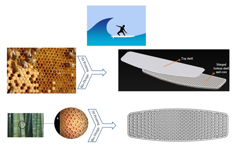
1. Introduction
2. Materials and Methods
2.1. Board Design (Uniform Honeycomb Sandwich Structure)
2.2. Materials and 3D Printing
2.3. D Printing and Assembling of the Board with the Honeycomb Core Structure
2.4. Experimental Three-Point Bending Test of Uniform Honeycomb
2.5. Analytical Solution
2.6. Finite Element Method and Experimental Validation
3. Results and Discussions
3.1. Testing Different Core Patterns
3.1.1. Hexagonal-Rhombic Structure
3.1.2. Triangular Honeycomb Structure
3.1.3. Hexagonal Carbon Lattice
3.1.4. Pinecone and Sunflower-Inspired Patterns
3.1.5. Spiderweb-Inspired Pattern
3.1.6. Functionally Graded Honeycomb Structure
3.2. Results of the Different Patterns
4. Conclusions
Author Contributions
Funding
Conflicts of Interest
References
- Caravaggi, P.; Leardini, A.; Belvedere, C.; Siegler, S. A novel Cervical Spine Protection device for reducing neck injuries in contact sports: Design concepts and preliminary in vivo testing*. Sports Biomech. 2018, 17, 1–13. [Google Scholar] [CrossRef] [PubMed]
- Shimoyama, K.; Seo, K.; Nishiwaki, T.; Jeong, S.; Obayashi, S. Design optimization of a sport shoe sole structure by evolutionary computation and finite element method analysis. Proc. Inst. Mech. Eng. Pt. P J. Sports Eng. Tech. 2011, 225, 179–188. [Google Scholar] [CrossRef]
- Sakellariou, K.; Rana, Z.A.; Jenkins, K.W. Optimisation of the surfboard fin shape using computational fluid dynamics and genetic algorithms. Proc. Inst. Mech. Eng. Pt. P J. Sports Eng. Tech. 2017, 231, 344–354. [Google Scholar] [CrossRef]
- Mosleh, Y.; Cajka, M.; Depreitere, B.; Vander Sloten, J.; Ivens, J. Designing safer composite helmets to reduce rotational accelerations during oblique impacts. J. Eng. Mech. 2018, 232, 479–491. [Google Scholar] [CrossRef]
- Gudimetla, P.; Kelson, N.; El-Atm, B. Analysis of the hydrodynamic performance of three- and four-fin surfboards using computational fluid dynamics. Aust. J. Mech. Eng. 2009, 7, 61–67. [Google Scholar] [CrossRef]
- Stier, B.; Bednarcyk, B.A.; Böddeker, T.; Springmann, R.; Simon, J.W.; Reese, S. Analysis, manufacturing, testing, and structural optimization of a novel composite kiteboard design. Proc. Inst. Mech. Eng. Pt. P J. Sports Eng. Tech. 2015, 229, 248–265. [Google Scholar] [CrossRef]
- Topolovich, L. Why A Broken Surfboard Is Bad For The Environment. Available online: https://www.wavetribe.com/blogs/eco/why-a-broken-surfboard-is-bad-for-the-environment (accessed on 15 September 2019).
- Musioł, M.; Sikorska, W.; Janeczek, H.; Wałach, W.; Hercog, A.; Johnston, B.; Rydz, J. (Bio)degradable polymeric materials for a sustainable future—part 1. Organic recycling of PLA/PBAT blends in the form of prototype packages with long shelf-life. Waste Manag. 2018, 77, 447–454. [Google Scholar] [CrossRef]
- Liu, Y.; Liu, W.; Gao, W.; Zhang, L.; Zhang, E. Mechanical responses of a composite sandwich structure with Nomex honeycomb core. J. Reinf. Plast. Comp. 2019, 38, 601–615. [Google Scholar] [CrossRef]
- Ha, N.S.; Lu, G.; Xiang, X. Energy absorption of a bio-inspired honeycomb sandwich panel. J. Mater. Sci. 2019, 54, 6286–6300. [Google Scholar] [CrossRef]
- Płatek, P.; Baranowski, P.; Cieplak, K.; Sarzyński, M.; Sienkiewicz, J.; Janiszewski, J.; Małachowski, J. Investigation on deformation process of cellular structures with gradient topology manufactured additively. AIP Conf. Proc. 2019, 2078, 020108. [Google Scholar] [CrossRef]
- Compton, B.G.; Lewis, J.A. 3D-printing of lightweight cellular composites. Adv. Mater 2014, 26, 5930–5935. [Google Scholar] [CrossRef] [PubMed]
- Bodaghi, M.; Damanpack, A.R.; Hu, G.F.; Liao, W.H. Large deformations of soft metamaterials fabricated by 3D printing. Mater. Design 2017, 131, 81–91. [Google Scholar] [CrossRef]
- Hao, J.; Wu, X.; Oporto, G.; Wang, J.; Dahle, G.; Nan, N. Deformation and failure behavior of wooden sandwich composites with Taiji Honeycomb Core under a three-point bending test. Materials 2018, 11, 2325. [Google Scholar] [CrossRef] [PubMed]
- Wang, Z.; Li, Z.; Xiong, W. Numerical study on three-point bending behavior of honeycomb sandwich with ceramic tile. Compos. Part B Eng. 2019, 167, 63–70. [Google Scholar] [CrossRef]
- Ngo, T.D.; Kashani, A.; Imbalzano, G.; Nguyen, K.T.Q.; Hui, D. Additive manufacturing (3D printing): A review of materials, methods, applications and challenges. Compos. Part B Eng. 2018, 143, 172–196. [Google Scholar] [CrossRef]
- Wang, X.; Jiang, M.; Zhou, Z.; Gou, J.; Hui, D. 3D printing of polymer matrix composites: A review and prospective. Compos. Part B Eng. 2017, 110, 442–458. [Google Scholar] [CrossRef]
- Wang, S.; Daelemans, L.; Fiorio, R.; Gou, M.; D’hooge, D.R.; De Clerck, K.; Cardon, L. Improving mechanical properties for extrusion-based additive manufacturing of poly (lactic acid) by annealing and blending with poly (3-hydroxybutyrate). Polymers 2019, 11, 1529. [Google Scholar] [CrossRef]
- Wang, K.; Li, S.; Rao, Y.; Wu, Y.; Peng, Y.; Yao, S.; Zhang, H.; Ahzi, S. Flexure Behaviors of ABS-based Composites Containing Carbon and Kevlar Fibers by Material Extrusion 3D Printing. Polymers 2019, 11, 1878. [Google Scholar] [CrossRef]
- Caminero, M.Á.; Chacón, J.M.; García-Plaza, E.; Núñez, P.J.; Reverte, J.M.; Becar, J.P. Additive Manufacturing of PLA-Based Composites Using Fused Filament Fabrication: Effect of Graphene Nanoplatelet Reinforcement on Mechanical Properties, Dimensional Accuracy and Texture. Polymers 2019, 11, 799. [Google Scholar] [CrossRef]
- Gately, R.D.; Beirne, S.; Latimer, G.; Shirlaw, M.; Kosasih, B.; Warren, A.; Steele, J.R.; In Het Panhuis, M. Additive Manufacturing, Modeling and Performance Evaluation of 3D Printed Fins for Surfboards. MRS Adv. 2017, 2, 913–920. [Google Scholar] [CrossRef]
- Park, J.-H.; Goo, B.; Park, K. Topology Optimization and Additive Manufacturing of Customized Sports Item Considering Orthotropic Anisotropy. Int. J. Precis. Eng. Man. 2019, 20, 1443–1450. [Google Scholar] [CrossRef]
- Cazón-Martín, A.; Iturrizaga-Campelo, M.; Matey-Muñoz, L.; Rodríguez-Ferradas, M.I.; Morer-Camo, P.; Ausejo-Muñoz, S. Design and manufacturing of shin pads with multi-material additive manufactured features for football players: A comparison with commercial shin pads. Proc. Inst. Mech. Eng. Pt. P J. Sports Eng. Tech. 2019, 233, 160–169. [Google Scholar] [CrossRef]
- Yu, Y.; Ying, L.; Hou, W.; Hu, P.; Jia, X.; Akhmet, G. Failure analysis of adhesively bonded steel corrugated sandwich structures under three-point bending. Compos. Struct. 2018, 184, 256–268. [Google Scholar] [CrossRef]
- Tidy, K. What Defines a Twin Tip Kiteboard? Available online: https://www.progression.me/blog/what-defines-a-twin-tip-kiteboard/ (accessed on 20 January 2020).
- Cozzens, R. CATIA V5 Workbook Release 19; SDC Publications: Mission, KS, USA, 2009. [Google Scholar]
- Gooch, J.W. ASTM D638. In Encyclopedic Dictionary of Polymers; Gooch, J.W., Ed.; Springer New York: New York, NY, USA, 2011; p. 51. [Google Scholar] [CrossRef]
- Raut, S.; Jatti, V.S.; Khedkar, N.K.; Singh, T.P. Investigation of the effect of built orientation on mechanical properties and total cost of FDM parts. Procedia Mater. Sci. 2014, 6, 1625–1630. [Google Scholar] [CrossRef]
- Sebas. Broken Surfboards: Where and Why it Happens. Available online: https://www.mundo-surf.com/blog/en/broken-surfboards-where-and-why-it-happens/ (accessed on 14 October 2019).
- Argyris, J.H.; Kelsey, S. Energy Theorems and Structural Analysis; Springer: Butterworths, London, 1960; Volume 60. [Google Scholar]
- Yap, Y.L.; Yeong, W.Y. Shape recovery effect of 3D printed polymeric honeycomb. Virtual Phys. Prototy. 2015, 10, 91–99. [Google Scholar] [CrossRef]
- Tan, T.; Rahbar, N.; Allameh, S.M.; Kwofie, S.; Dissmore, D.; Ghavami, K.; Soboyejo, W.O. Mechanical properties of functionally graded hierarchical bamboo structures. Acta Biomater. 2011, 7, 3796–3803. [Google Scholar] [CrossRef]
- Janssen, J.J.A. Designing and Building with Bamboo; International Network for Bamboo and Rattan: Eindhoven, The Netherlands, 2000. [Google Scholar]
- Crutcher, R. Timber Bamboo Cross-Section. Available online: http://www.microlabgallery.com/gallery/Bamboo%20Macro%201.aspx (accessed on 5 December 2019).


| Dimensions | ASTM D638 TYPE 1 |
|---|---|
| W—Narrow section width | 13 mm |
| L—Narrow section Length | 57 mm |
| Wo—Overall width | 19 mm |
| Lo—Overall length | 165 mm |
| R—Radius of fillet | 76 mm |
| t—Thickness | 5 mm |
© 2020 by the authors. Licensee MDPI, Basel, Switzerland. This article is an open access article distributed under the terms and conditions of the Creative Commons Attribution (CC BY) license (http://creativecommons.org/licenses/by/4.0/).
Share and Cite
Soltani, A.; Noroozi, R.; Bodaghi, M.; Zolfagharian, A.; Hedayati, R. 3D Printing On-Water Sports Boards with Bio-Inspired Core Designs. Polymers 2020, 12, 250. https://doi.org/10.3390/polym12010250
Soltani A, Noroozi R, Bodaghi M, Zolfagharian A, Hedayati R. 3D Printing On-Water Sports Boards with Bio-Inspired Core Designs. Polymers. 2020; 12(1):250. https://doi.org/10.3390/polym12010250
Chicago/Turabian StyleSoltani, Aref, Reza Noroozi, Mahdi Bodaghi, Ali Zolfagharian, and Reza Hedayati. 2020. "3D Printing On-Water Sports Boards with Bio-Inspired Core Designs" Polymers 12, no. 1: 250. https://doi.org/10.3390/polym12010250
APA StyleSoltani, A., Noroozi, R., Bodaghi, M., Zolfagharian, A., & Hedayati, R. (2020). 3D Printing On-Water Sports Boards with Bio-Inspired Core Designs. Polymers, 12(1), 250. https://doi.org/10.3390/polym12010250