PLA/PA Bio-Blends: Induced Morphology by Extrusion

 , , ,
, , ,  ,
, 
Abstract
1. Introduction
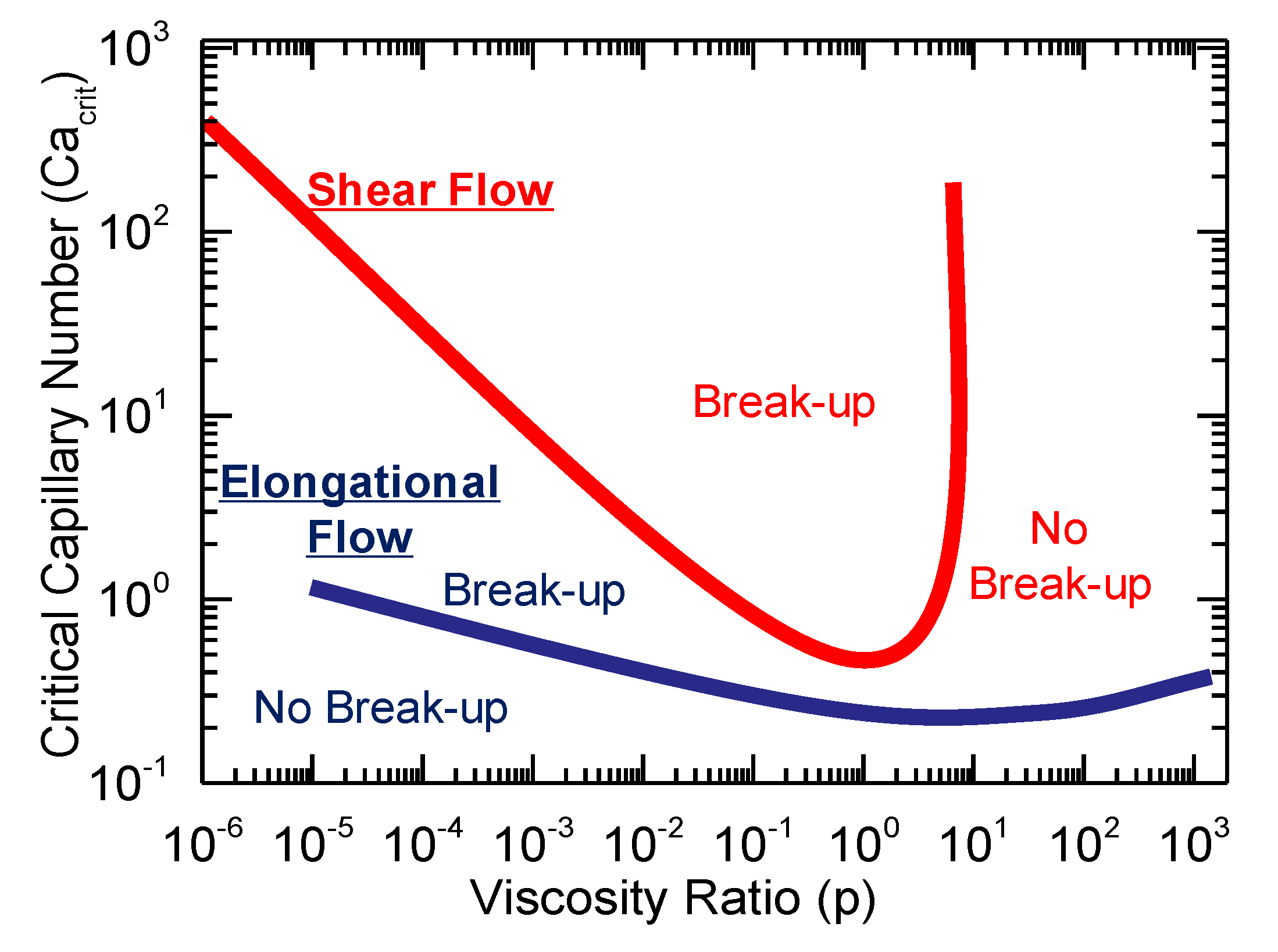
- (i)
- undergo deformation from a spherical shape to ellipsoids or fibrils,
- (ii)
- break-up into smaller ones, or
- (iii)
- coalesce when they collide, depending on how well the morphology has been stabilized (compatibilized).
2. Materials and Methods
2.1. Materials
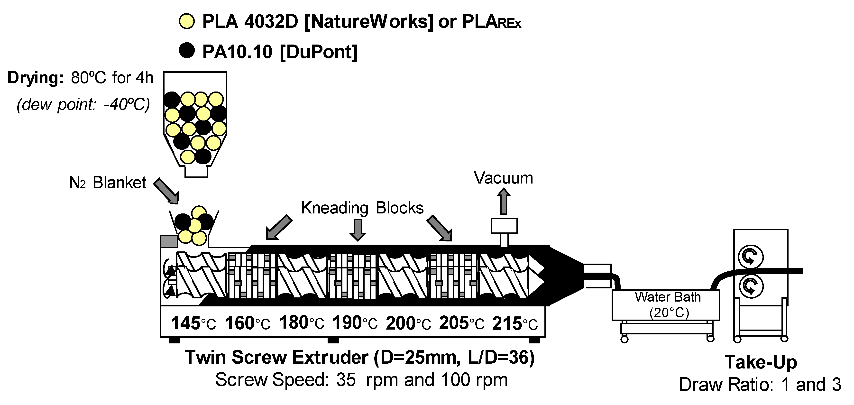
2.2. Bio-blends Preparation
2.3. Rheological Characterisation
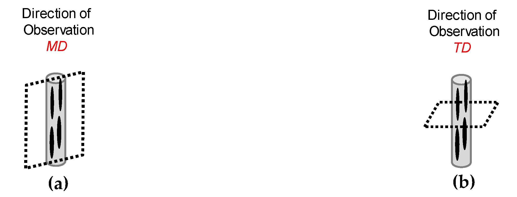
2.4. Morphological Characterization
2.5. Thermo-Mechanical Characterisation
3. Results and Discussions
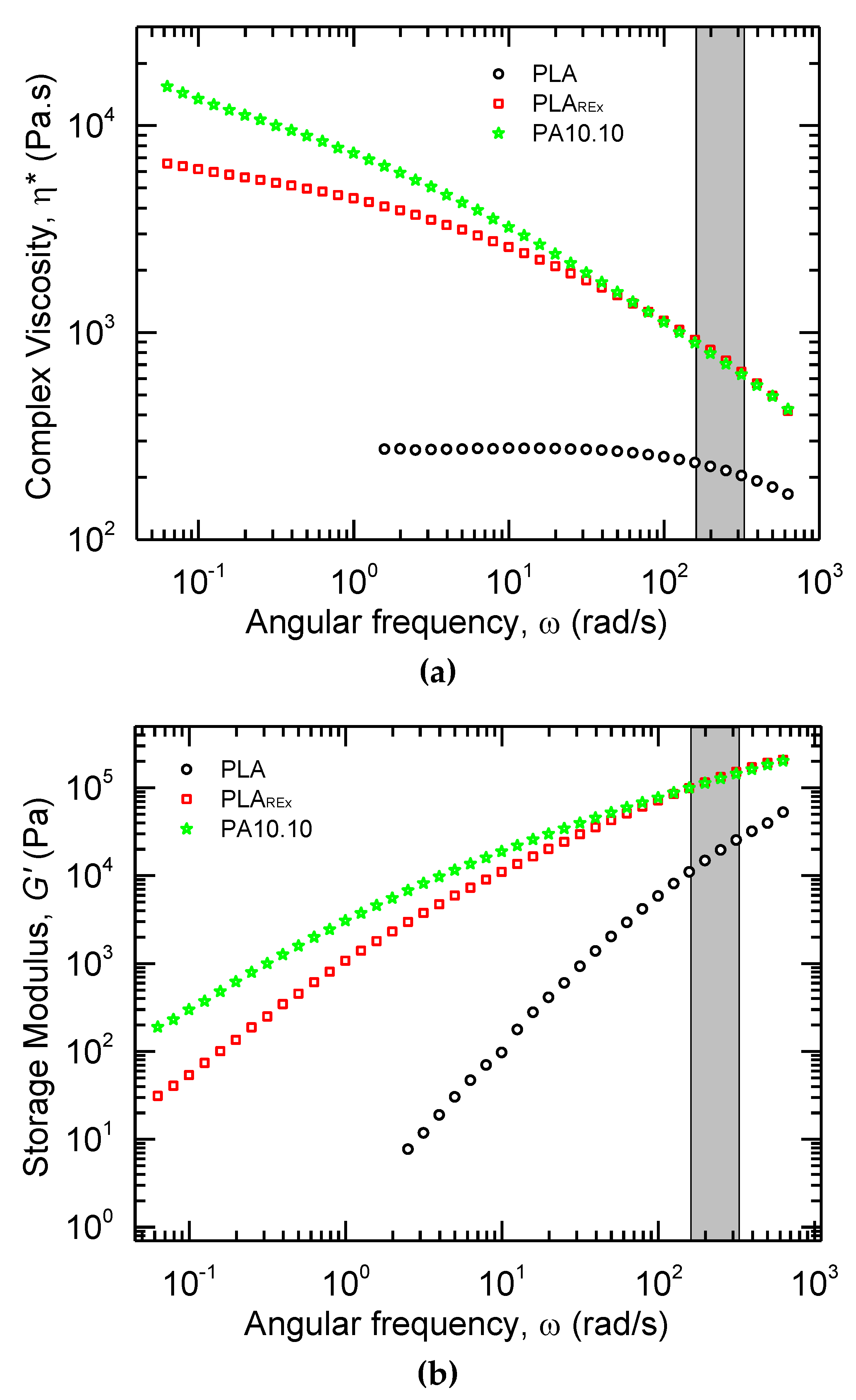
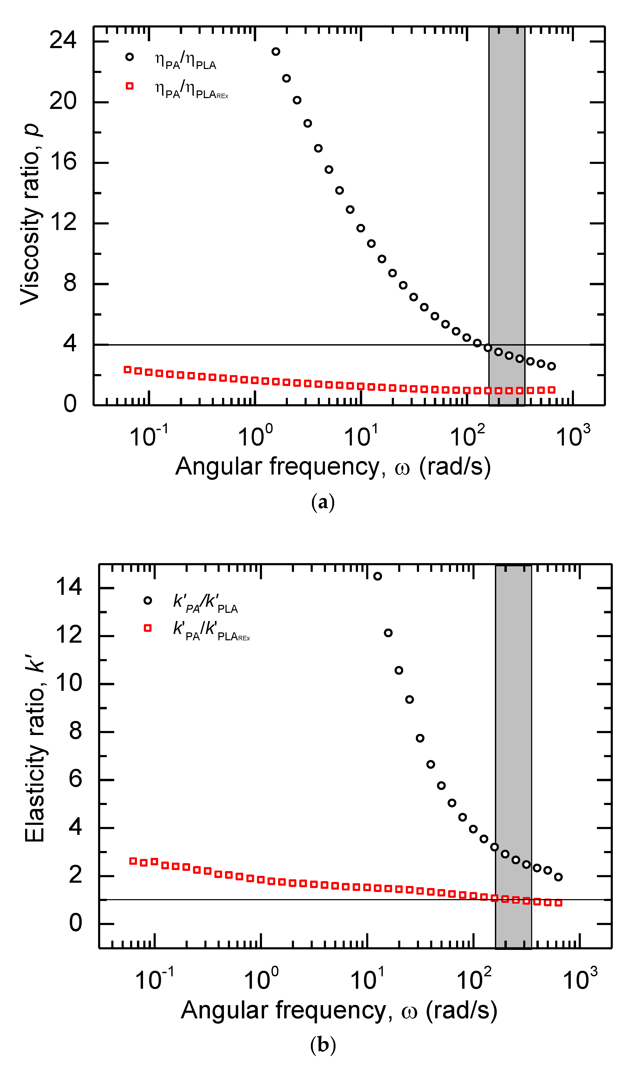
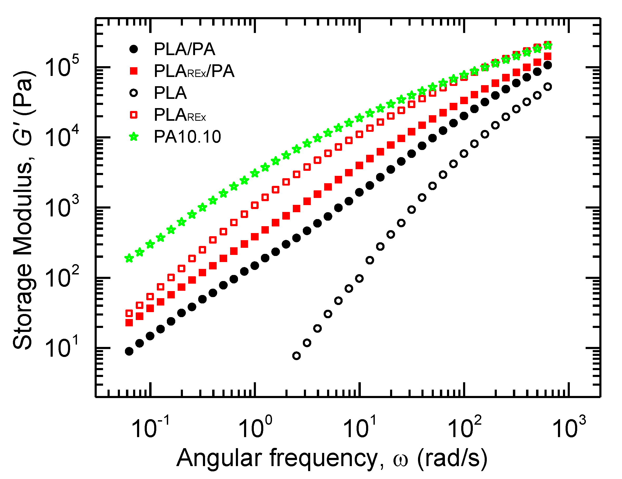
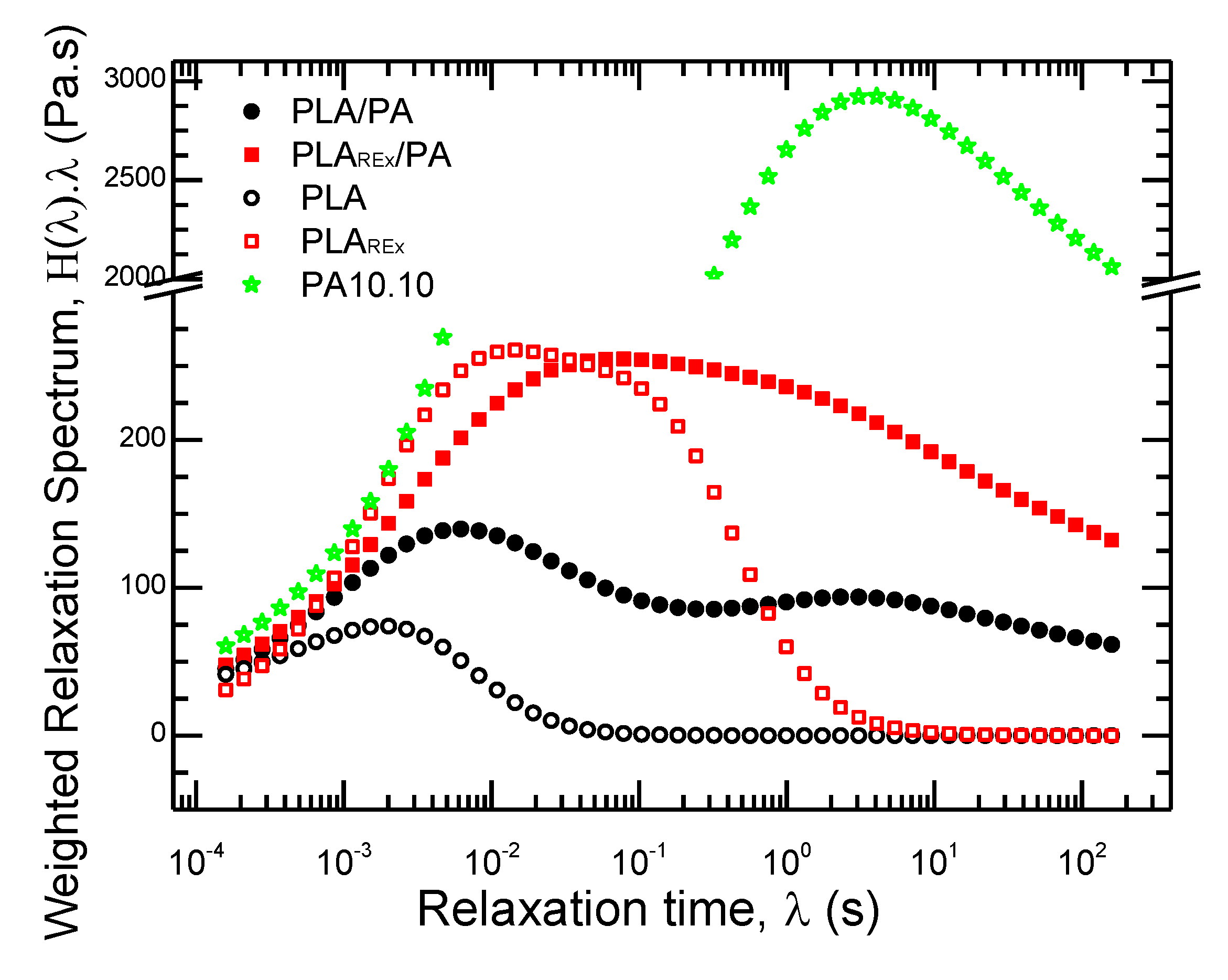
3.1. Microfibrillation Potential Using a Rheological Analysis
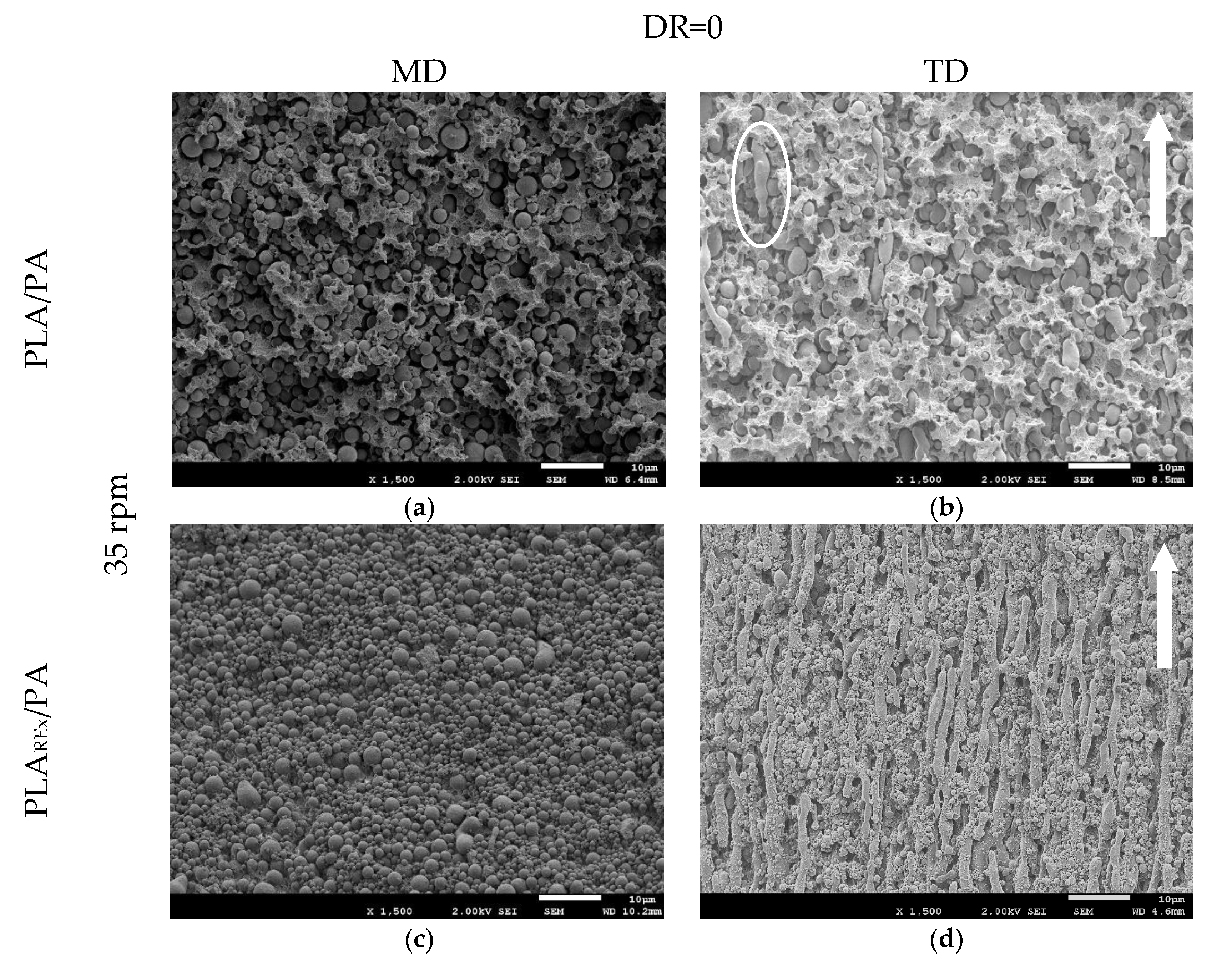
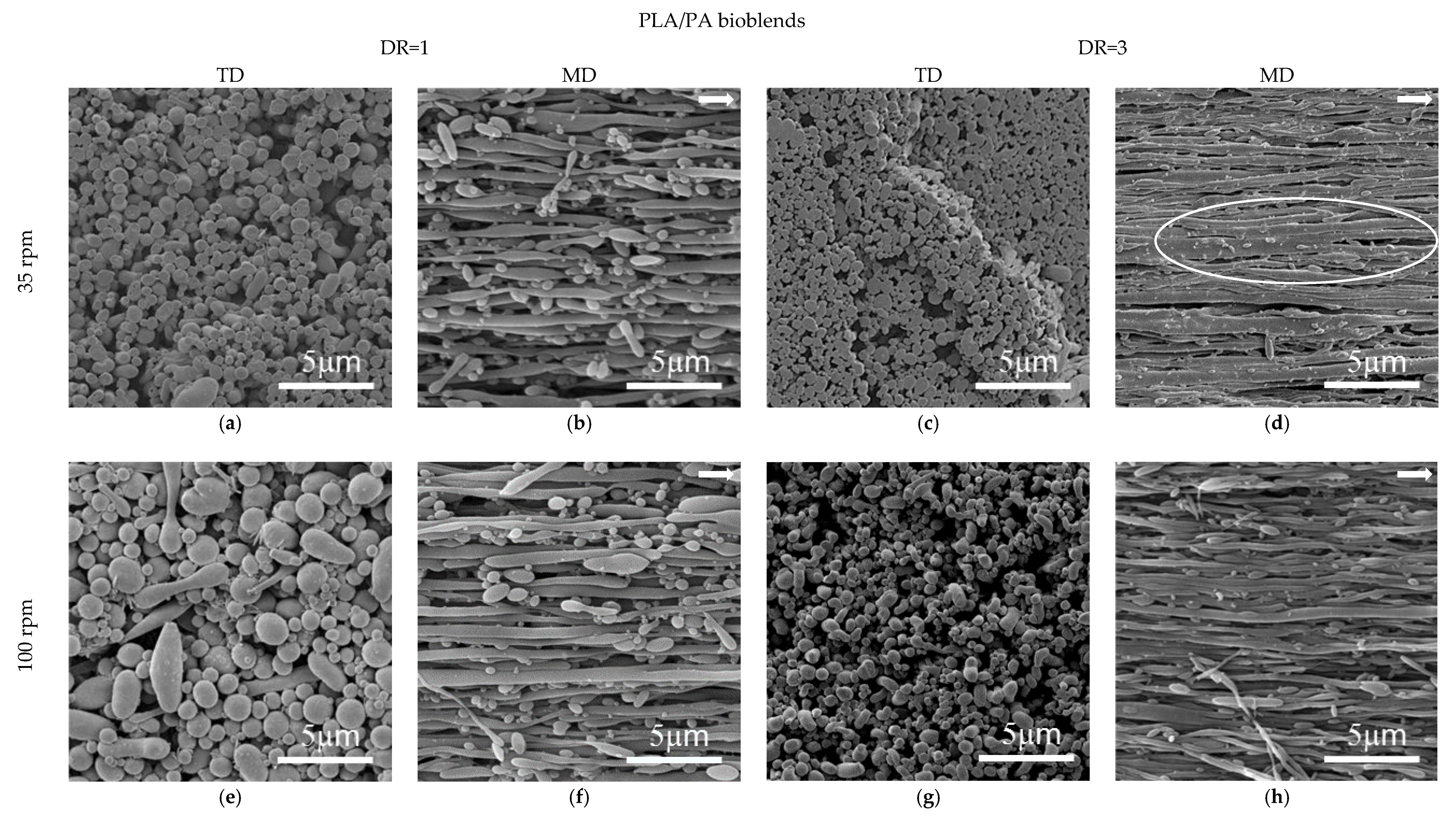
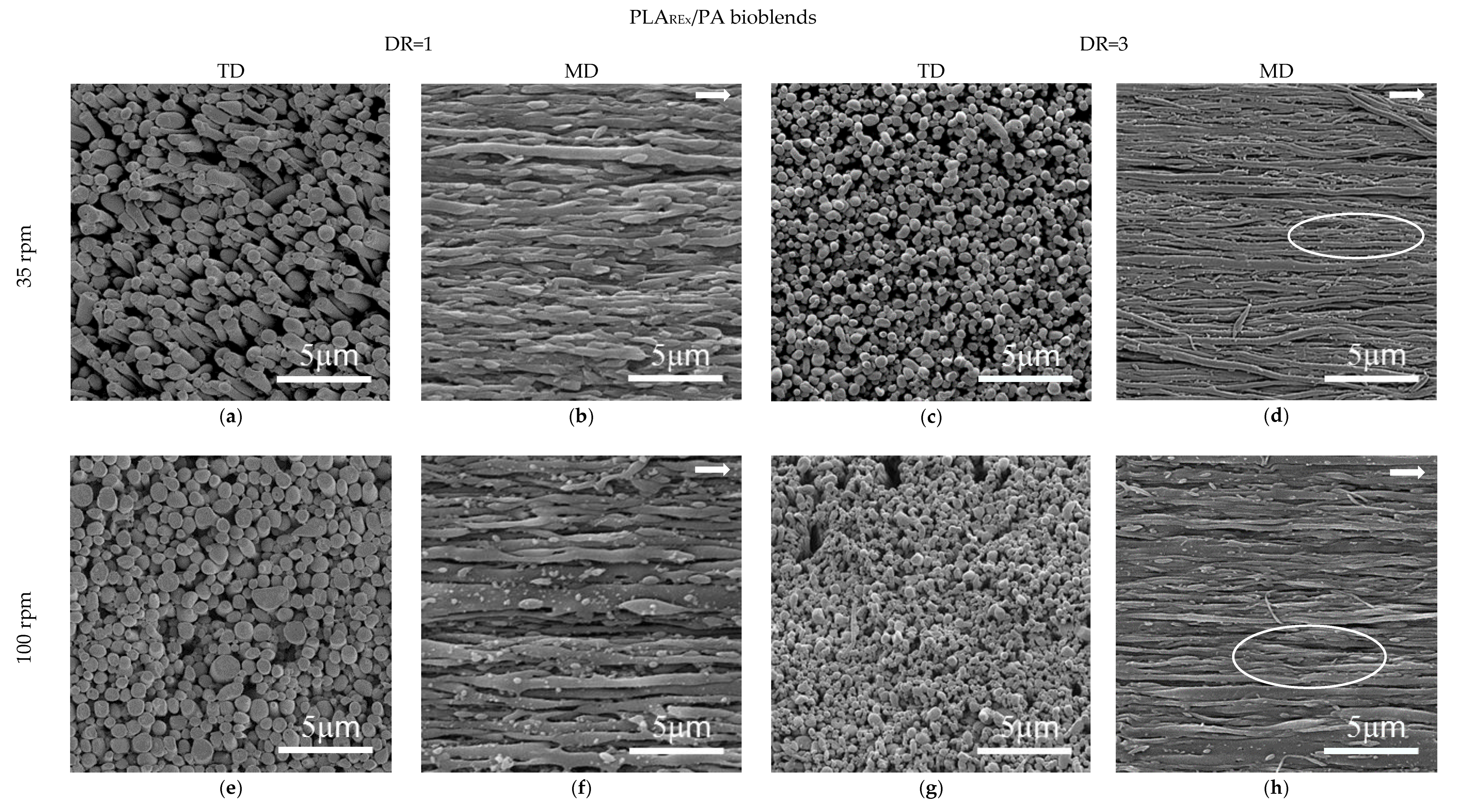
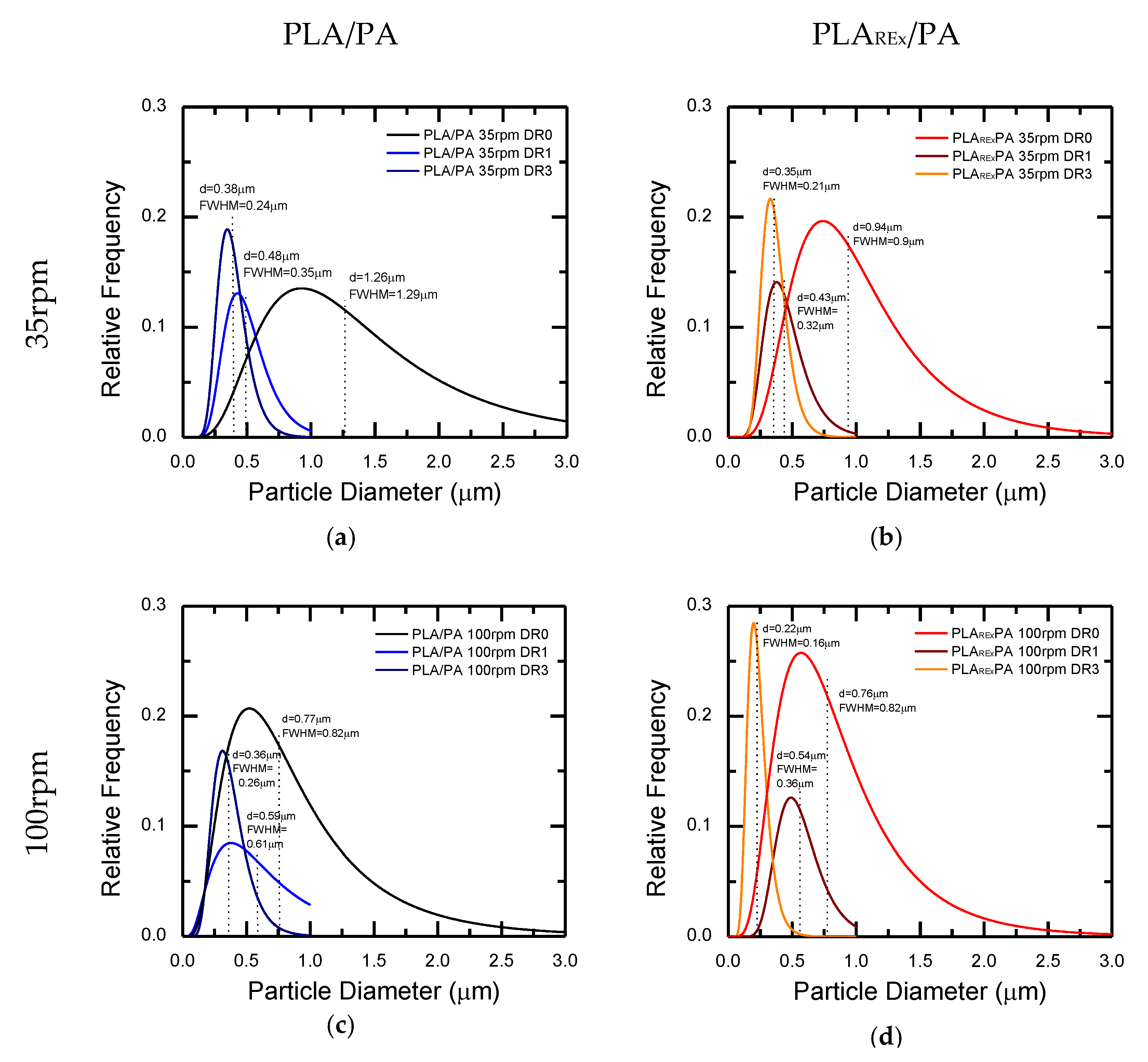
3.2. Morphological Analysis of the Hot Stretched Bio-blends
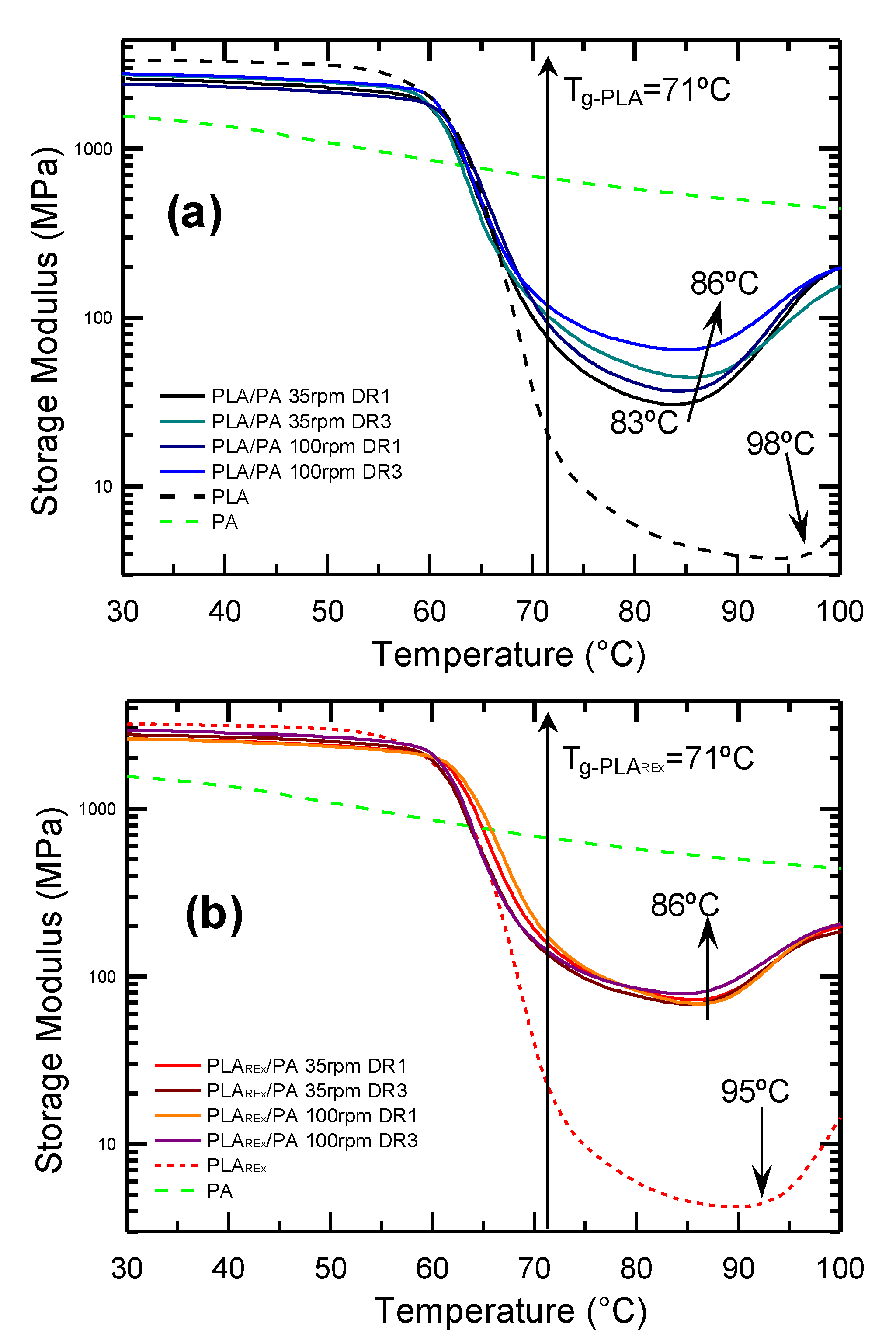
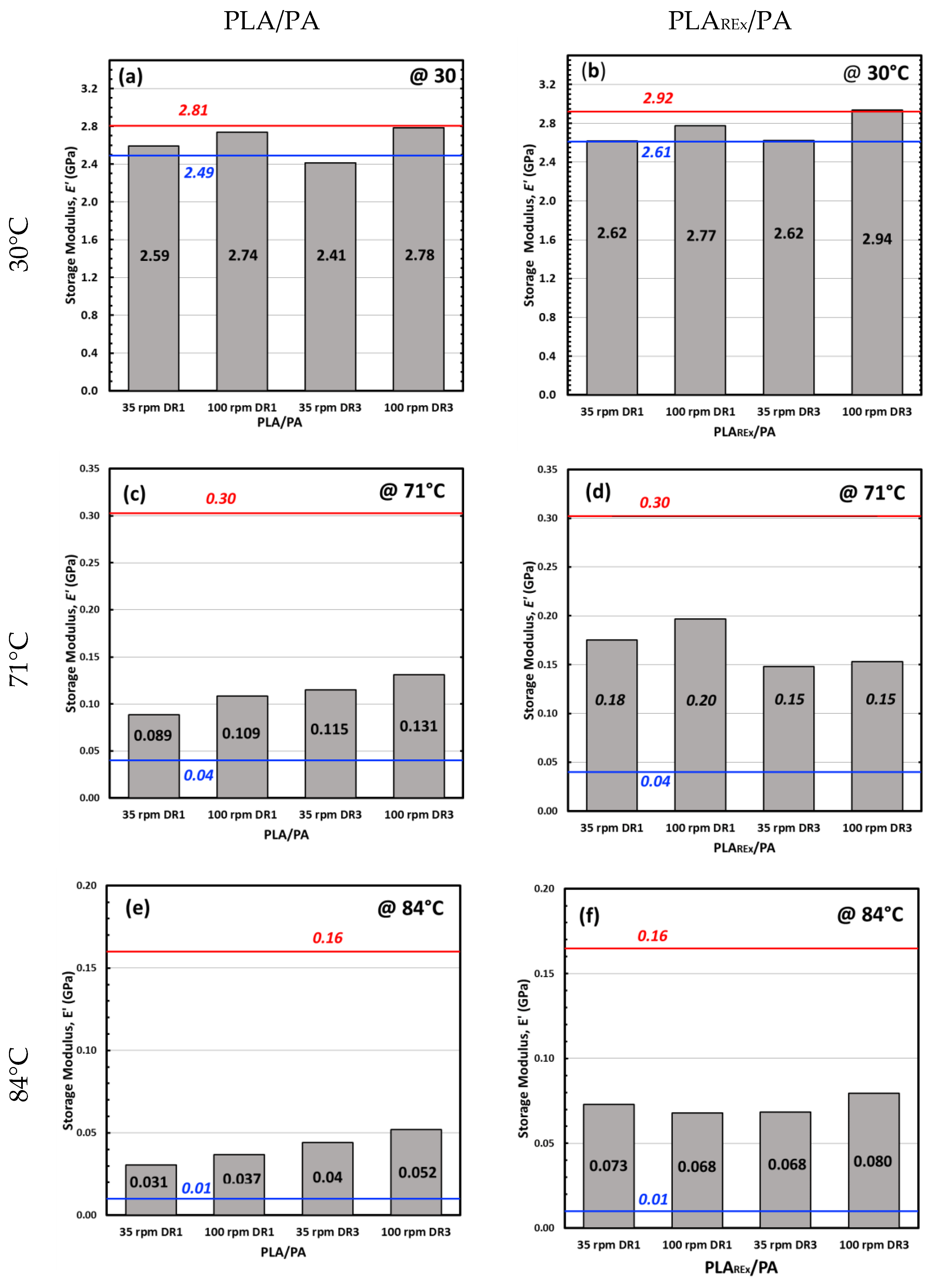
3.3. Dynamic Mechanical-Thermal Analysis
4. Conclusions
Author Contributions
Funding
Acknowledgments
Conflicts of Interest
References
- Nakajima, H.; Dijkstra, P.; Loos, K. The recent developments in biobased polymers toward general and engineering applications: Polymers that are upgraded from biodegradable polymers, analogous to petroleum-derived polymers, and newly developed. Polymers 2017, 9, 523. [Google Scholar] [CrossRef] [PubMed]
- Vadori, R.; Misra, M.; Mohanty, A.K. Sustainable biobased blends from the reactive extrusion of polylactide and acrylonitrile butadiene styrene. J. Appl. Polym. Sci. 2016, 133, 43771. [Google Scholar] [CrossRef]
- Siracusa, V.; Rocculi, P.; Romani, S.; Rosa, M.D. Biodegradable polymers for food packaging: A review. Trends Food Sci. Technol. 2008, 19, 634–643. [Google Scholar] [CrossRef]
- Garlotta, D. A Literature Review of Poly(Lactic Acid). J. Polym. Environ. 2001, 9, 63–84. [Google Scholar] [CrossRef]
- Auras, R.; Harte, B.; Selke, S. An overview of polylactides as packaging materials. Macromol. Biosci. 2004, 4, 835–864. [Google Scholar] [CrossRef]
- Zeng, J.-B.; Li, K.-A.; Du, A.-K. Compatibilization strategies in poly(lactic acid)-based blends. RSC Adv. 2015, 5, 32546–32565. [Google Scholar] [CrossRef]
- Yu, L.; Dean, K.; Li, L. Polymer blends and composites from renewable resources. Prog. Polym. Sci. 2006, 31, 576–602. [Google Scholar] [CrossRef]
- Anderson, K.S.; Schreck, K.M.; Hillmyer, M.A. Toughening polylactide. Polym. Rev. 2008, 48, 85–108. [Google Scholar] [CrossRef]
- Babu, R.P.; O’Connor, K.; Seeram, R. Current progress on bio-based polymers and their future trends. Prog. Biomater. 2013, 2, 8. [Google Scholar] [CrossRef]
- Bitinis, N.; Verdejo, R.; López-Manchado, M.A. Modification of PLA by Blending with Elastomers. In Poly(Lactic Acid) Science and Technology: Processing, Properties, Additives and Applications; Jiménez, A., Peltzer, M., Ruseckaite, R., Eds.; The Royal Society of Chemistry: Cambridge, UK, 2015; pp. 195–213. [Google Scholar]
- Detyothin, S.; Kathuria, A.; Jaruwattanayon, W.; Selke, S.E.M.; Auras, R. Poly(lactic acid) Blends. In Poly(Lactic Acid): Synthesis, Structures, Properties, Processing, and Application; Auras, R., Lim, L.-T., Selke, S.E.M., Tsuji, H., Eds.; John Wiley & Sons, Inc.: Hoboken, NJ, USA, 2010; pp. 217–272. [Google Scholar]
- Starý, Z. Thermodynamics and Morphology and Compatibilization of Polymer Blends. In Characterization of Polymer Blends: Miscibility, Morphology and Interfaces; Thomas, S., Grohens, Y., Jyotishkumar, P., Eds.; Wiley-VCH Verlag & Co. KGaA: Weinheim, Germany, 2015; pp. 93–132. [Google Scholar]
- Heeres, H.J.; van Maastrigt, F.; Picchioni, F. Polymeric Blends with Biopolymers. In Handbook of Biopolymer-Based Materials: From Blends and Composites to Gels and Complex Networks; Thomas, S., Durand, D., Chassenieux, C., Jyotishkumar, P., Eds.; Wiley-VCH Verlag GmbH & Co. KGaA: Weinheim, Germany, 2013; pp. 143–172. [Google Scholar]
- Kakroodi, A.R.; Kazemi, Y.; Ding, W.D.; Ameli, A.; Park, C.B. Poly(lactic acid)-Based in Situ Microfibrillar Composites with Enhanced Crystallization Kinetics, Mechanical Properties, Rheological Behavior, and Foaming Ability. Biomacromolecules 2015, 16, 3925–3935. [Google Scholar] [CrossRef]
- Stoclet, G.; Seguela, R.; Lefebvre, J.M. Morphology, thermal behavior and mechanical properties of binary blends of compatible biosourced polymers: Polylactide/polyamide11. Polymer 2011, 52, 1417–1425. [Google Scholar] [CrossRef]
- Yousfi, M.; Dadouche, T.; Chomat, D.; Samuel, C.; Soulestin, J.; Lacrampe, M.F.; Krawczak, P. Development of nanofibrillar morphologies in poly(l-lactide)/poly(amide) blends: Role of the matrix elasticity and identification of the critical shear rate for the nodular/fibrillar transition. RSC Adv. 2018, 8, 22023–22041. [Google Scholar] [CrossRef]
- Heshmati, V.; Zolali, A.M.; Favis, B.D. Morphology development in poly (lactic acid)/polyamide11 biobased blends: Chain mobility and interfacial interactions. Polymer 2017, 120, 197–208. [Google Scholar] [CrossRef]
- Cailloux, J.; Abt, T.; Garcia-Masabet, V.; Santana, O.; Sánchez-Soto, M.; Carrasco, F.; Maspoch, M.L.; Carrasco, F.; Sanchez-Soto, M.; Santana, O.; et al. Effect of the viscosity ratio on the PLA/PA10.10 bioblends morphology and mechanical properties. Express Polym. Lett. 2018, 12, 569–582. [Google Scholar] [CrossRef]
- Li, Z.M.; Yang, W.; Huang, R.; Fang, X.P.; Yang, M.B. Essential work of fracture parameters of in-situ microfibrillar poly(ethylene terephthalate)/polyethylene blend: Influences of blend composition. Macromol. Mater. Eng. 2004, 289, 426–433. [Google Scholar] [CrossRef]
- Friedrich, K.; Evstatiev, M.; Fakirov, S.; Evstatiev, O.; Ishii, M.; Harrass, M. Microfibrillar reinforced composites from PET/PP blends: Processing, morphology and mechanical properties. Compos. Sci. Technol. 2005, 65, 107–116. [Google Scholar] [CrossRef]
- Rizvi, A.; Tabatabaei, A.; Barzegari, M.R.; Mahmood, S.H.; Park, C.B. In situ fibrillation of CO2-philic polymers: Sustainable route to polymer foams in a continuous process. Polymer 2013, 54, 4645–4652. [Google Scholar] [CrossRef]
- Rasselet, D.; Caro-Bretelle, A.S.; Taguet, A.; Lopez-Cuesta, J.M. Reactive compatibilization of PLA/PA11 blends and their application in additive manufacturing. Materials 2019, 12, 485. [Google Scholar] [CrossRef]
- Rizvi, A.; Park, C.B.; Favis, B.D. Tuning viscoelastic and crystallization properties of polypropylene containing in-situ generated high aspect ratio polyethylene terephthalate fibrils. Polymer 2015, 68, 83–91. [Google Scholar] [CrossRef]
- Rizvi, A.; Park, C.B. Dispersed polypropylene fibrils improve the foaming ability of a polyethylene matrix. Polymer 2014, 55, 4199–4205. [Google Scholar] [CrossRef]
- Van Hemelrijck, E.; Van Puyvelde, P.; Macosko, C.W.; Moldenaers, P. The effect of block copolymer architecture on the coalescence and interfacial elasticity in compatibilized polymer blends. J. Rheol. 2005, 49, 783–798. [Google Scholar] [CrossRef]
- Van Puyvelde, P.; Moldenaers, P. Rheology-Morphology Relationships in Immiscible Polymer Blends. In Micro- and Nanostructured Multiphase Polymer Blend Systems; Harrats, C., Thomas, S., Groeninckx, G., Eds.; CRC Press: Boca Raton, FL, USA, 2005; pp. 421–440. [Google Scholar]
- Ding, W.; Chen, Y.; Liu, Z.; Yang, S. In situ nano-fibrillation of microinjection molded poly(lactic acid)/poly(ε-caprolactone) blends and comparison with conventional injection molding. RSC Adv. 2015, 5, 92905–92917. [Google Scholar] [CrossRef]
- Vanoene, H. Modes of dispersion of viscoelastic fluids in flow. J. Colloid Interface Sci. 1972, 40, 448–467. [Google Scholar] [CrossRef]
- Wang, J.; Zhang, Y.; Sun, W.; Chu, S.; Chen, T.; Sun, A.; Guo, J.; Xu, G. Morphology Evolutions and Mechanical Properties of In Situ Fibrillar Polylactic Acid/Thermoplastic Polyurethane Blends Fabricated by Fused Deposition Modeling. Macromol. Mater. Eng. 2019, 304. [Google Scholar] [CrossRef]
- Grace, H.P. Dispersion Phenomena in High Viscosity Immiscible Fluid Systems and Application of Static Mixers As Dispersion Devices in Such Systems. Chem. Eng. Commun. 1982, 14, 225–277. [Google Scholar] [CrossRef]
- Van Puyvelde, P.; Moldenaers, P. Rheology and morphology development in immiscible polymer blends. Br. Soc. Rheol. 2005, 101–145. [Google Scholar]
- Pesneau, I.; At Kadi, A.; Bousmina, M.; Cassagnau, P.; Michel, A. From polymer blends to in situ polymer/polymer composites: Morphology control and mechanical properties. Polym. Eng. Sci. 2002, 42, 1990–2004. [Google Scholar] [CrossRef]
- Lerdwijitjarud, W.; Sirivat, A.; Larsonb, R.G. Influence of elasticity on dispersed-phase droplet size in immiscible polymer blends in simple shearing flow. Polym. Eng. Sci. 2002, 42, 798–809. [Google Scholar] [CrossRef]
- Chapleau, N.; Favis, B.D. Droplet/fibre transitions in immiscible polymer blends generated during melt processing. J. Mater. Sci. 1995, 30, 142–150. [Google Scholar] [CrossRef]
- Li, Z.-M.; Li, L.-B.; Shen, K.-Z.; Yang, M.-B.; Huang, R. In-situ microfibrillar PET/iPP blend via slit die extrusion, hot stretching, and quenching: Influence of hot stretch ratio on morphology, crystallization, and crystal structure of iPP at a fixed PET concentration. J. Polym. Sci. Part B Polym. Phys. 2004, 42, 4095–4106. [Google Scholar] [CrossRef]
- Hakim, R.H.; Cailloux, J.; Santana, O.O.; Bou, J.; Sánchez-Soto, M.; Odent, J.; Raquez, J.M.; Dubois, P.; Carrasco, F.; Maspoch, M.L. PLA/SiO2 composites: Influence of the filler modifications on the morphology, crystallization behavior, and mechanical properties. J. Appl. Polym. Sci. 2017, 134, 45367. [Google Scholar] [CrossRef]
- Cailloux, J.; Santana, O.O.; Franco-Urquiza, E.; Bou, J.J.; Carrasco, F.; Maspoch, M.L. Sheets of branched poly(lactic acid) obtained by one-step reactive extrusion-calendering process: Physical aging and fracture behavior. J. Mater. Sci. 2014, 49, 4093–4107. [Google Scholar] [CrossRef]
- Yi, X.; Ji, X.; Li, Z.-M.; Xu, L.; Zhong, G.-J.; Wang, Y.-L. Morphology and properties of isotactic polypropylene/poly(ethylene terephthalate) in situ microfibrillar reinforced blends: Influence of viscosity ratio. Eur. Polym. J. 2010, 46, 719–730. [Google Scholar] [CrossRef]
- Cailloux, J.; Santana, O.O.; Maspoch, M.L.; Bou, J.J.; Carrasco, F. Using viscoelastic properties to quantitatively estimate the amount of modified poly(lactic acid) chains through reactive extrusion. J. Rheol. 2015, 59, 1191–1227. [Google Scholar] [CrossRef]
- Walha, F.; Lamnawar, K.; Maazouz, A.; Jaziri, M. Rheological, morphological and mechanical studies of sustainably sourced polymer blends based on poly(lactic acid) and polyamide 11. Polymers 2016, 8, 61. [Google Scholar] [CrossRef]
- Marechal, P.; Legras, R.; Dekoninck, J.M. Postcondensation and oxidation processes in molten polyamide 6. J. Polym. Sci. Part A Polym. Chem. 1993, 31, 2057–2067. [Google Scholar] [CrossRef]
- Salehiyan, R.; Malwela, T.; Ray, S.S. Thermo-oxidative degradation study of melt-processed polyethylene and its blend with polyamide using time-resolved rheometry. Polym. Degrad. Stab. 2017, 139, 130–137. [Google Scholar] [CrossRef]
- Mighri, F.; Carreau, P.J.; Ajji, A. Influence of elastic properties on drop deformation and breakup in shear flow. J. Rheol. 1998, 42, 1477–1490. [Google Scholar] [CrossRef]
- Mighri, F.; Ajji, A.; Carreau, P.J. Influence of elastic properties on drop deformation in elongational flow. J. Rheol. 1997, 41, 1183–1201. [Google Scholar] [CrossRef]
- Van Puyvelde, P.; Oommen, Z.; Koets, P.; Groeninckx, G.; Moldenaers, P. Effect of Reactive Compatibilization on the Interfacial Slip in Nylon-6/EPR Blends. Polym. Eng. Sci. 2003, 43, 71–77. [Google Scholar] [CrossRef]
- Zhao, R.; Macosko, C.W. Slip at polymer–polymer interfaces: Rheological measurements on coextruded multilayers. J. Rheol. 2002, 46, 145–167. [Google Scholar] [CrossRef]
- Ougizawa, T.; Inoue, T. Morphology of Polymer Blends. In Polymer Blends Handbook; Utracki, L.A., Wilkie, C.A., Eds.; Springer Netherlands: Dordrecht, The Netherlands, 2014; pp. 875–918. [Google Scholar]
- Palierne, J.F. Linear rheology of viscoelastic emulsions with interfacial tension. Rheol. Acta 1990, 29, 204–214. [Google Scholar] [CrossRef]
- Tucker, C., III; Moldenaers, P. Microstructural Evolution. Annu. Rev. Fluid Mech. 2002, 34, 177–210. [Google Scholar] [CrossRef]


| Viscosity Ratio (p) | Break-up Mechanism | Description |
|---|---|---|
| Much lower 0.1 | Tip streaming  | The break-up occurs at the tip of the deformed droplet and generally produce very fine droplets |
| 0.1 < p < 1 | Necking  | The deformed droplet breaks up into two daughter droplets. |
End pinching | The deformation produces a dumbbell shape, after which the break-up occurs in the two droplets formed at the ends. | |
| 1 < p < 3.8 | Rayleigh break-up  | Interfacial instabilities produce disturbances that will break up the fibril into a line of droplets. |
| p > 3.8 | No break-up  | The break-up of the droplet under shear is not possible. |
| Sample Nomenclature | % w/w of Pristine Polymers | ||
|---|---|---|---|
| PLA | PLAREx | PA10.10 | |
| PLA/PA | 70 | - | 30 |
| PLAREx/PA | - | 70 | 30 |
| PLA/PA | PLAREx/PA | |
|---|---|---|
| Mean Size (μm) | 1.26 | 0.94 |
| Full Width at Half Maximum (μm) | 1.29 | 0.90 |
© 2019 by the authors. Licensee MDPI, Basel, Switzerland. This article is an open access article distributed under the terms and conditions of the Creative Commons Attribution (CC BY) license (http://creativecommons.org/licenses/by/4.0/).
Share and Cite
García-Masabet, V.; Santana Pérez, O.; Cailloux, J.; Abt, T.; Sánchez-Soto, M.; Carrasco, F.; Maspoch, M.L. PLA/PA Bio-Blends: Induced Morphology by Extrusion. Polymers 2020, 12, 10. https://doi.org/10.3390/polym12010010
García-Masabet V, Santana Pérez O, Cailloux J, Abt T, Sánchez-Soto M, Carrasco F, Maspoch ML. PLA/PA Bio-Blends: Induced Morphology by Extrusion. Polymers. 2020; 12(1):10. https://doi.org/10.3390/polym12010010
Chicago/Turabian StyleGarcía-Masabet, Violeta, Orlando Santana Pérez, Jonathan Cailloux, Tobias Abt, Miguel Sánchez-Soto, Félix Carrasco, and María Lluïsa Maspoch. 2020. "PLA/PA Bio-Blends: Induced Morphology by Extrusion" Polymers 12, no. 1: 10. https://doi.org/10.3390/polym12010010
APA StyleGarcía-Masabet, V., Santana Pérez, O., Cailloux, J., Abt, T., Sánchez-Soto, M., Carrasco, F., & Maspoch, M. L. (2020). PLA/PA Bio-Blends: Induced Morphology by Extrusion. Polymers, 12(1), 10. https://doi.org/10.3390/polym12010010