Embedding Ultra-High-Molecular-Weight Polyethylene Fibers in 3D-Printed Polylactic Acid (PLA) Parts

 , ,
, ,
Abstract
1. Introduction
2. Materials and Methods
3. Results
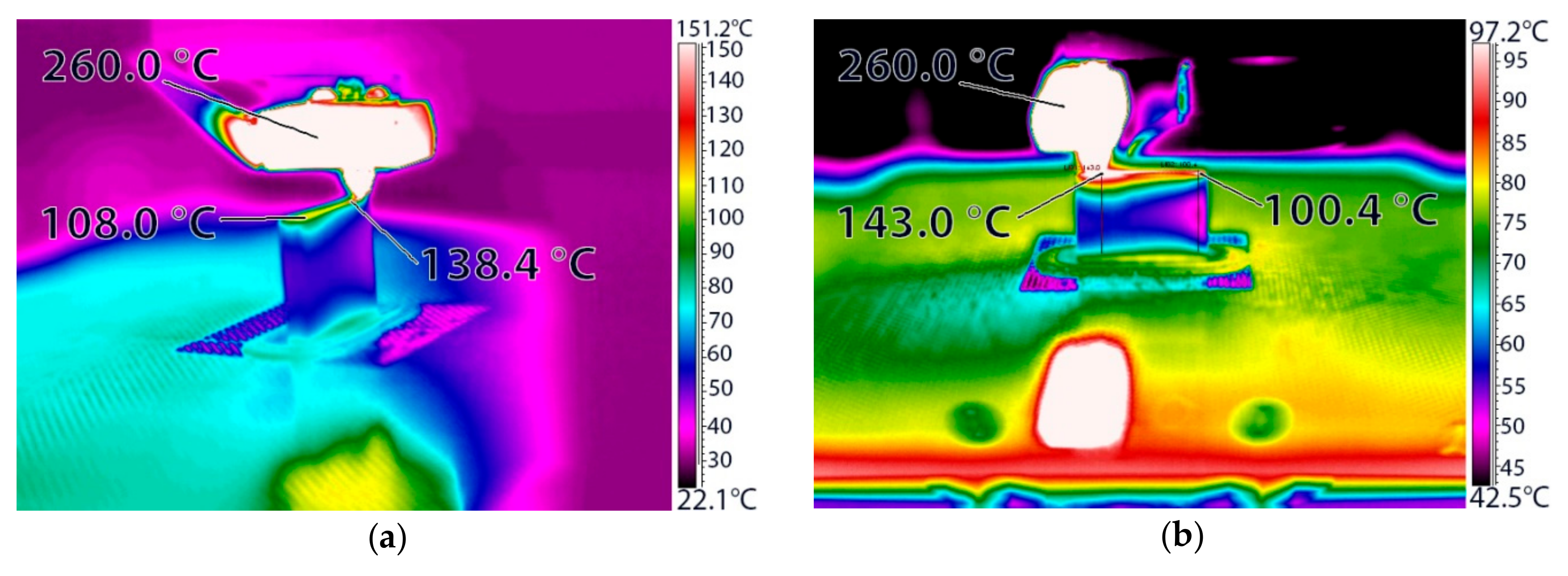
3.1. Maximum Extrusion Temperature
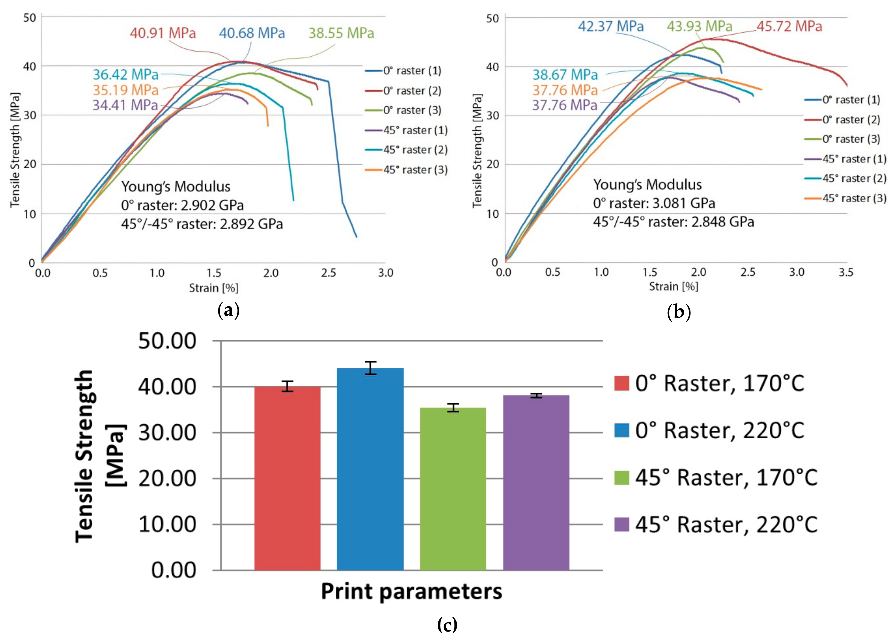
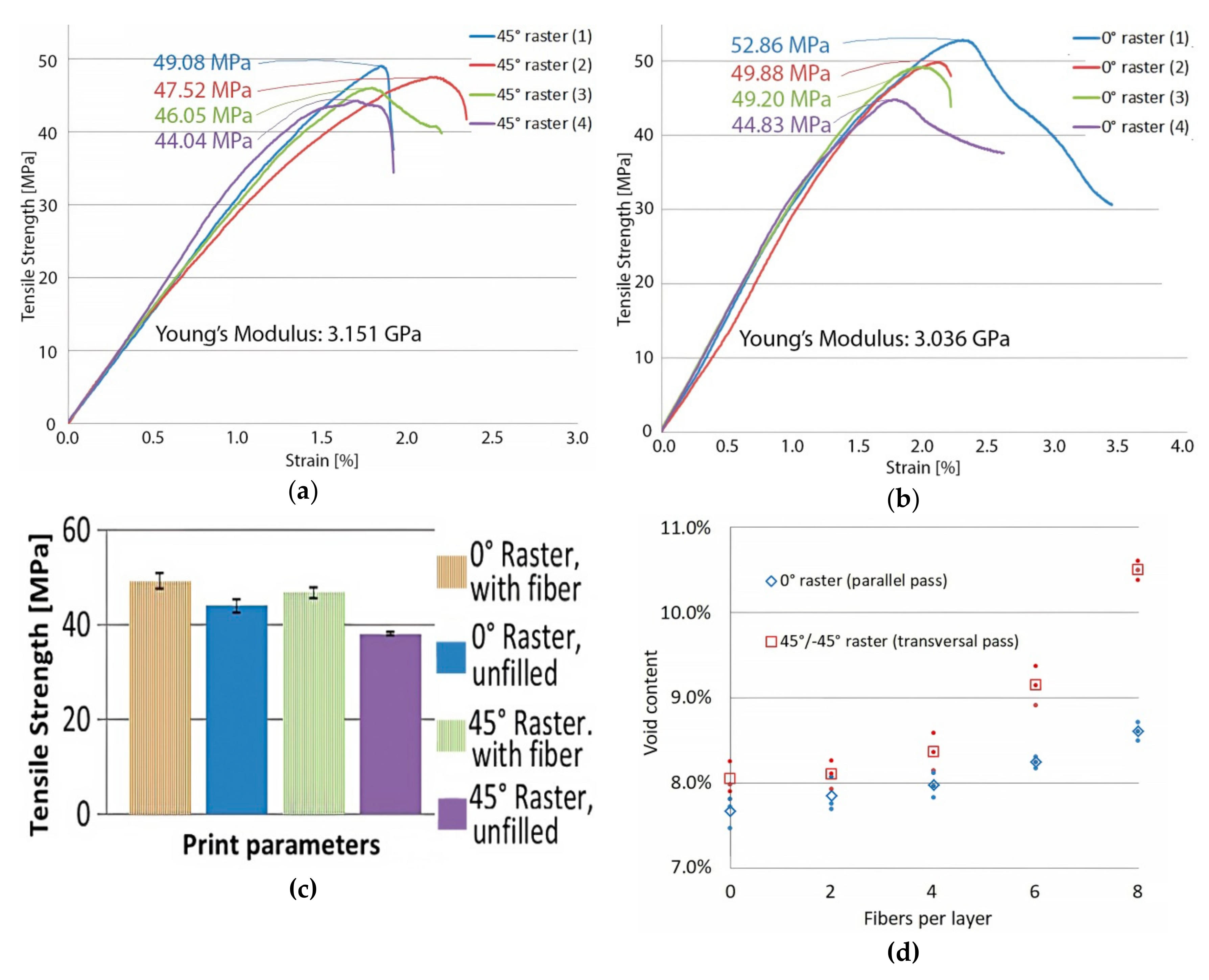
3.2. Unfilled PLA Specimens
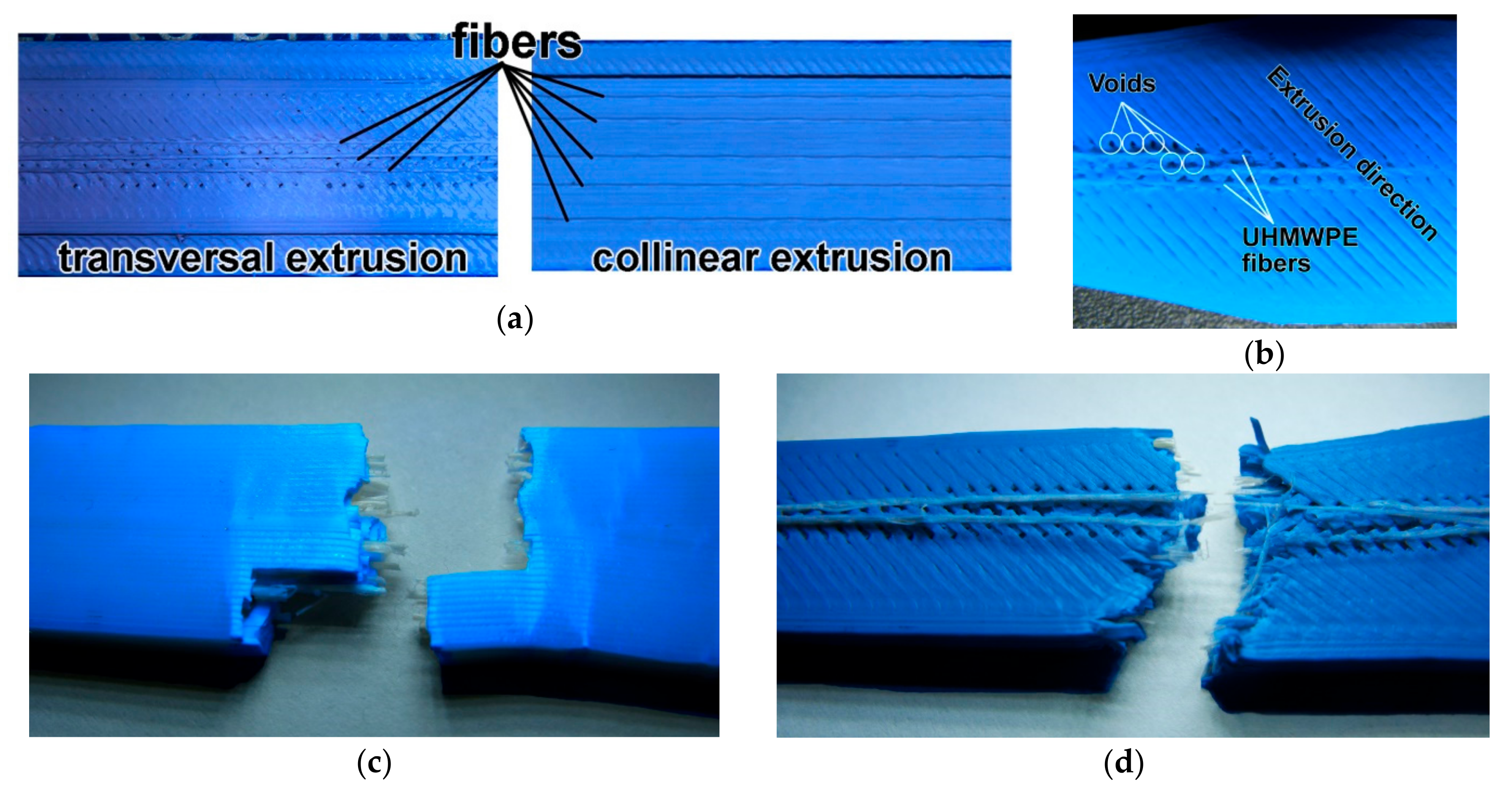
3.3. PLA Specimens Filled with Dyneema Fibers
4. Discussion
5. Conclusions
Author Contributions
Funding
Conflicts of Interest
References
- Wang, J.; Xie, H.; Weng, Z.; Senthil, T.; Wu, L. A novel approach to improve mechanical properties of parts fabricated by fused deposition modeling. Mater. Des. 2016, 105, 152–159. [Google Scholar] [CrossRef]
- Kaynak, C.; Varsavas, S.D. Performance comparison of the 3D-printed and injection-molded PLA and its elastomer blend and fiber composites. J. Thermoplast. Compos. Mater. 2018, 32, 501–520. [Google Scholar] [CrossRef]
- Dawoud, M.; Taha, I.; Ebeid, S.J. Mechanical behaviour of ABS: An experimental study using FDM and injection moulding techniques. J. Manuf. Process. 2016, 21, 39–45. [Google Scholar] [CrossRef]
- Balderrama-Armendariz, C.O.; Macdonald, E.; Espalin, D.; Cortes-Saenz, D.; Wicker, R.; Maldonado-Macías, A. Torsion analysis of the anisotropic behavior of FDM technology. Int. J. Adv. Manuf. Technol. 2018, 96, 307–317. [Google Scholar] [CrossRef]
- Belter, J.T.; Dollar, A.M. Strengthening of 3D Printed Fused Deposition Manufactured Parts Using the Fill Compositing Technique. PLoS ONE 2015, 10, e0122915. [Google Scholar] [CrossRef] [PubMed]
- Tekinalp, H.L.; Kunc, V.; Velez-Garcia, G.; Duty, C.E.; Love, L.; Naskara, A.K.; Blueb, C.A.; Ozcan, S. Highly Oriented Carbon Fiber in Polymer Composite Structures via Additive Manufacturing. Compos. Sci. Technol. 2014, 105, 144–150. [Google Scholar] [CrossRef]
- Stein, H.L. Ultrahigh molecular weight polyethylenes (uhmwpe). Eng. Mater. Handb. 1998, 2, 167–171. [Google Scholar]
- Xu, M.-M.; Huang, G.-Y.; Feng, S.-S.; McShane, G.J.; Stronge, W.J. Static and Dynamic Properties of Semi-Crystalline Polyethylene. Polymers 2016, 8, 77. [Google Scholar] [CrossRef]
- Wu, Y.-J.; Seferis, J.C.; Lorentz, V.; Wu, Y. Evaluations of an aramid fiber in nonwoven processes for honeycomb applications. J. Appl. Polym. Sci. 2002, 86, 1149–1156. [Google Scholar] [CrossRef]
- Brown, J.R.; Ennis, B.C. Thermal Analysis of Nomex® and Kevlar® Fibers. Text. Res. J. 1977, 47, 62–66. [Google Scholar] [CrossRef]
- Sanborn, B.; DiLeonardi, A.M.; Weerasooriya, T. Tensile Properties of Dyneema SK76 Single Fibers at Multiple Loading Rates Using a Direct Gripping Method. J. Dyn. Behav. Mater. 2015, 1, 4–14. [Google Scholar] [CrossRef]
- Werff, H.; Vlasblom, M.; Balzano, L.; Engels, T.; Heisserer, U.; Oosterlinck, F.; Coussens, B. New Developments of the Dyneema® Ultra High Molecular Weight Polyethylene Fiber. In Proceedings of the International Symposium on Fiber Science and Technology 2014 (ISF 2014), Tokyo, Japan, 28 September–1 October 2014. [Google Scholar]
- Tappa, K.; Jammalamadaka, U. Novel Biomaterials Used in Medical 3D Printing Techniques. J. Funct. Biomater. 2018, 9, 17. [Google Scholar] [CrossRef] [PubMed]
- Södergård, A.; Stolt, M. Properties of lactic acid based polymers and their correlation with composition. Prog. Polym. Sci. 2002, 27, 1123–1163. [Google Scholar] [CrossRef]
- Grossman, R.F.; Nwabunma, D. Poly(Lactic Acid): Synthesis, Structures, Properties, Processing, and Applications, 1st ed.; John Wiley & Sons: Hoboken, NJ, USA, 2011. [Google Scholar]
- Ramot, Y.; Zada, M.H.; Domb, A.J.; Nyska, A. Biocompatibility and safety of PLA and its copolymers. Adv. Drug Deliv. Rev. 2016, 107, 153–162. [Google Scholar] [CrossRef] [PubMed]
- Antoniac, I.; Popescu, D.; Zapciu, A.; Antoniac, A.; Miculescu, F.; Moldovan, H. Magnesium Filled Polylactic Acid (PLA) Material for Filament Based 3D Printing. Materials 2019, 12, 719. [Google Scholar] [CrossRef]
- Domínguez-Robles, J.; Martin, N.K.; Fong, M.L.; Stewart, S.A.; Irwin, N.J.; Rial-Hermida, M.I.; Donnelly, R.F.; Larrañeta, E. Antioxidant PLA Composites Containing Lignin for 3D Printing Applications: A Potential Material for Healthcare Applications. Pharmaceutics 2019, 11, 165. [Google Scholar] [CrossRef]
- Popescu, D.; Zapciu, A.; Tarba, C.; Laptoiu, D. Fast production of customized three-dimensional-printed hand splints. Rapid Prototyp. J. 2019. [Google Scholar] [CrossRef]
- Yang, Y.; Boom, R.; Irion, B.; Van Heerden, D.-J.; Kuiper, P.; De Wit, H. Recycling of composite materials. Chem. Eng. Process. 2012, 51, 53–68. [Google Scholar] [CrossRef]
- Le Duigou, A.; Barbé, A.; Guillou, E.; Castro, M. 3D printing of continuous flax fibre reinforced biocomposites for structural applications. Mater. Des. 2019, 180, 107884. [Google Scholar] [CrossRef]
- Depuydt, D.; Balthazar, M.; Hendrickx, K.; Six, W.; Ferraris, E.; Desplentere, F.; Ivens, J.; Van Vuure, A.W. Production and characterization of bamboo and flax fiber reinforced polylactic acid filaments for fused deposition modeling (FDM). Polym. Compos. 2019, 40, 1951–1963. [Google Scholar] [CrossRef]
- Ochi, S. Mechanical properties of kenaf fibers and kenaf/PLA composites. Mech. Mater. 2008, 40, 446–452. [Google Scholar] [CrossRef]
- Mazzanti, V.; Mollica, F. Rheological behavior of wood flour filled poly-(lactic acid): Temperature and concentration dependence. Polym. Compos. 2019, 40, E169–E176. [Google Scholar] [CrossRef]
- Bouafif, H.; Koubaa, A.; Perre, P.; Cloutier, A.; Riedl, B. Wood particle/high-density polyethylene composites: Thermal sensitivity and nucleating ability of wood particles. J. Appl. Polym. Sci. 2009, 113, 593–600. [Google Scholar] [CrossRef]
- Caraccio, A.; Hintze, P. Trash-to-Gas: Converting Space Trash into Useful Products. In Proceedings of the AIAA 43rd International Conference on Environmental Systems, Vail, CO, USA, 14–18 July 2013. [Google Scholar]
- Silverstein, M.; Breuer, O. Wettability and flotation of etched ultra high molecular weight polyethylene fibres. Polymers 1993, 34, 3421–3427. [Google Scholar] [CrossRef]
- Silverstein, M.; Breuer, O. Relationship between surface properties and adhesion for etched ultra-high-molecular-weight polyethylene fibers. Compos. Sci. Technol. 1993, 48, 151–157. [Google Scholar] [CrossRef]
- Rezaei, M.; Ebrahimi, N.G.; Shirzad, A. Study on Mechanical Properties of UHMWPE/PET Composite Using Robust Design. Iran. Polim. J. 2005, 15, 3–12. [Google Scholar]
- Valerga, A.P.; Batista, M.; Salguero, J.; Girot, F. Influence of PLA Filament Conditions on Characteristics of FDM Parts. Materials 2018, 11, 1322. [Google Scholar] [CrossRef]
- Farah, S.; Anderson, D.G.; Langer, R. Physical and mechanical properties of PLA, and their functions in widespread applications—A comprehensive review. Adv. Drug Deliv. Rev. 2016, 107, 367–392. [Google Scholar] [CrossRef]
- Popescu, D.; Zapciu, A.; Amza, C.; Baciu, F.; Marinescu, R. FDM process parameters influence over the mechanical properties of polymer specimens: A review. Polym. Test. 2018, 69, 157–166. [Google Scholar] [CrossRef]
- ASTM D638—14 Standard Test Method for Tensile Properties of Plastics. Available online: https://www.astm.org/Standards/D638 (accessed on 14 September 2019).
- Amza, C.G.; Zapciu, A.; Eyþórsdóttir, A.; Björnsdóttir, A.; Borg, J. Mechanical properties of 3D printed composites with ABS/ASA substrate and glass fiber inserts. MATEC Web Conf. 2019, 290, 04002. [Google Scholar] [CrossRef]
- ASTM D2734—16 Standard Test Methods for Void Content of Reinforced Plastics. Available online: https://www.astm.org/Standards/D2734 (accessed on 28 October 2019).
- ASTM D792—13 Standard Test Methods for Density and Specific Gravity (Relative Density) of Plastics by Displacement. Available online: https://www.astm.org/Standards/D792 (accessed on 28 October 2019).
- Li, B.; Zhao, M.; Wan, X. The influence of void distribution on transverse mechanical properties of unidirectional composites. In Proceedings of the International Conference on Mechanical and Aerospace Engineering (ICMAE), Prague, Czech Republic, 22–25 July 2017. [Google Scholar]
- Blok, L.; Longana, M.; Yu, H.; Woods, B. An investigation into 3D printing of fibre reinforced thermoplastic composites. Addit. Manuf. 2018, 22, 176–186. [Google Scholar] [CrossRef]
- Hasenjaeger, B. Programming and Simulating Automated Fiber Placement (AFP) CNC Machines. SAMPE J. 2013, 49, 7–13. [Google Scholar]
- Raspall, F.; Velu, R.; Vaheed, N.M. Fabrication of complex 3D composites by fusing automated fiber placement (AFP) and additive manufacturing (AM) technologies. Adv. Manuf. Polym. Compos. Sci. 2019, 5, 6–16. [Google Scholar] [CrossRef]
- Mark, G.T.; Benhaim, D.; Parangi, A.; Sklaroff, B. Methods for Fiber Reinforced Additive Manufacturing. U.S. Patent 9,694,544, 4 July 2017. [Google Scholar]
- Mark, G.T.; Gozdz, A.S. Three Dimensional Printer for Fiber Reinforced Composite Filament Fabrication. U.S. Patent 9,956,725, 1 May 2018. [Google Scholar]
- Anindyajati, A.; Boughton, P.; Ruys, A.J. Fabrication and Microstructure Evaluation of Fibrous Composite for Acetabular Labrum Implant. Mater. Sci. Forum 2017, 900, 17–22. [Google Scholar] [CrossRef]
- Anindyajati, A.; Boughton, P.; Ruys, A.J. Mechanical and Cytocompatibility Evaluation of UHMWPE/PCL/Bioglass® Fibrous Composite for Acetabular Labrum Implant. Materials 2019, 12, 916. [Google Scholar] [CrossRef]
- Urquijo, J.; Guerrica-Echevarría, G.; Eguiazábal, J.I. Melt processed PLA/PCL blends: Effect of processing method on phase structure, morphology, and mechanical properties. J. Appl. Polym. Sci. 2015, 132, 42641. [Google Scholar] [CrossRef]
- Matta, A.; Rao, R.U.; Suman, K.; Rambabu, V. Preparation and Characterization of Biodegradable PLA/PCL Polymeric Blends. Procedia Mater. Sci. 2014, 6, 1266–1270. [Google Scholar] [CrossRef]
- Guerra, A.J.; Cano, P.; Rabionet, M.; Puig, T.; Ciurana, J. 3D-Printed PCL/PLA Composite Stents: Towards a New Solution to Cardiovascular Problems. Materials 2018, 11, 1679. [Google Scholar] [CrossRef]


| Parameter | Value |
|---|---|
| Raster angle | 0° or 45°/−45° |
| Specimen cross-section | 3.2 mm × 13 mm |
| Contour width | 1.2 mm |
| Infill | 100% |
| Fiber Diameter (mm) | Layer Height (mm) | Extrusion Path | Maximum Extrusion Temperature (°C) |
|---|---|---|---|
| 0.08 | 0.10/0.20 | Collinear/Transversal 45° | N/A 1 |
| 0.10 | 0.10 | Collinear | N/A |
| 0.10 | 0.10 | Transversal 45° | 170 |
| 0.10 | 0.20 | Collinear/Transversal 45° | N/A |
| 0.16 | 0.20 | Collinear | 174 |
| 0.16 | 0.20 | Transversal 45° | 186 |
| Specimen | Tg (°C) | Tcc (°C) | Tm (°C) | ΔHc (J/g) | ΔHm (J/g) | Xc (%) |
|---|---|---|---|---|---|---|
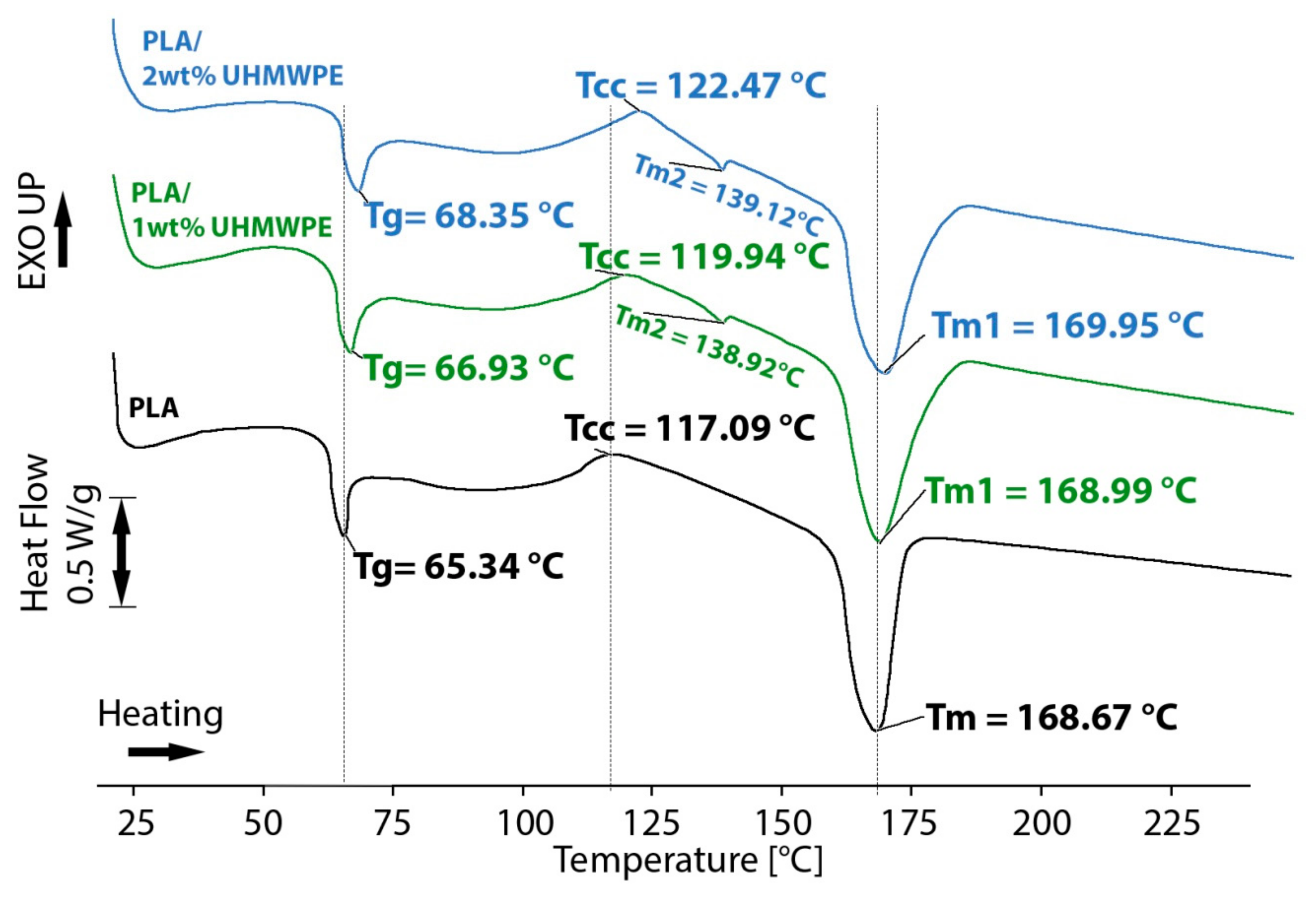
| 100 PLA | 65.34 ± 0.32 | 117.09 ± 0.27 | 168.67 ± 0.44 | 14.33 ± 0.10 | 34.08 ± 0.12 | 36.64 |
| 99/1 (w/w) PLA/UHMWPE | 66.89 ± 0.29 | 119.94 ± 0.22 | 168.99 ± 23 (PLA) 138.92 ± 0.14 (UHMWPE) | 11.69 ± 0.21 | 40.01 ± 0.34 | 43.02 |
| 98/2 (w/w) PLA/UHMWPE | 68.35 ± 0.50 | 122.47 ± 0.43 | 169.95 ± 40 (PLA) 139.12 ± 0.36 (UHMWPE) | 11.96 ± 0.19 | 37.62 ± 0.50 | 40.45 |
© 2019 by the authors. Licensee MDPI, Basel, Switzerland. This article is an open access article distributed under the terms and conditions of the Creative Commons Attribution (CC BY) license (http://creativecommons.org/licenses/by/4.0/).
Share and Cite
Amza, C.G.; Zapciu, A.; Eyþórsdóttir, A.; Björnsdóttir, A.; Borg, J. Embedding Ultra-High-Molecular-Weight Polyethylene Fibers in 3D-Printed Polylactic Acid (PLA) Parts. Polymers 2019, 11, 1825. https://doi.org/10.3390/polym11111825
Amza CG, Zapciu A, Eyþórsdóttir A, Björnsdóttir A, Borg J. Embedding Ultra-High-Molecular-Weight Polyethylene Fibers in 3D-Printed Polylactic Acid (PLA) Parts. Polymers. 2019; 11(11):1825. https://doi.org/10.3390/polym11111825
Chicago/Turabian StyleAmza, Cătălin Gheorghe, Aurelian Zapciu, Arnheiður Eyþórsdóttir, Auðbjörg Björnsdóttir, and Jonathan Borg. 2019. "Embedding Ultra-High-Molecular-Weight Polyethylene Fibers in 3D-Printed Polylactic Acid (PLA) Parts" Polymers 11, no. 11: 1825. https://doi.org/10.3390/polym11111825
APA StyleAmza, C. G., Zapciu, A., Eyþórsdóttir, A., Björnsdóttir, A., & Borg, J. (2019). Embedding Ultra-High-Molecular-Weight Polyethylene Fibers in 3D-Printed Polylactic Acid (PLA) Parts. Polymers, 11(11), 1825. https://doi.org/10.3390/polym11111825