Transport Asymmetry of Novel Bi-Layer Hybrid Perfluorinated Membranes on the Base of MF-4SC Modified by Halloysite Nanotubes with Platinum

 ,
,  ,
, 
Abstract
:
1. Introduction
2. Experiment
2.1. Materials and Instruments
2.2. Сlay Nanotubes Modification
2.3. Hybrid Membrane Synthesis
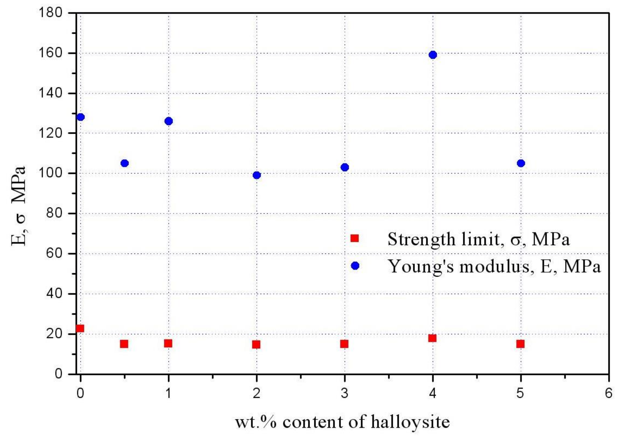
2.4. Mechanical Testing
3. Membrane Characterization
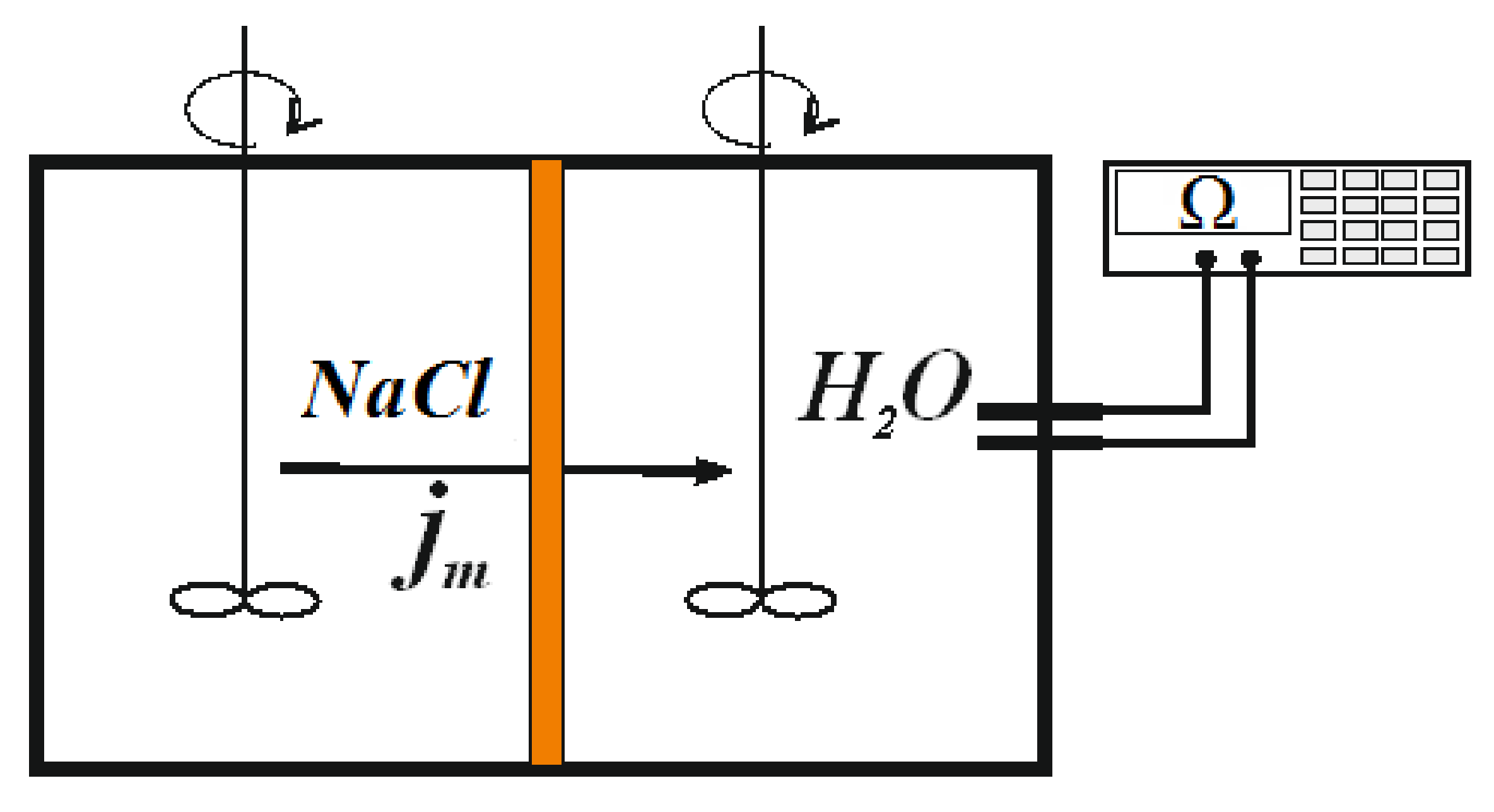
3.1. Diffusion Permeability Measurements
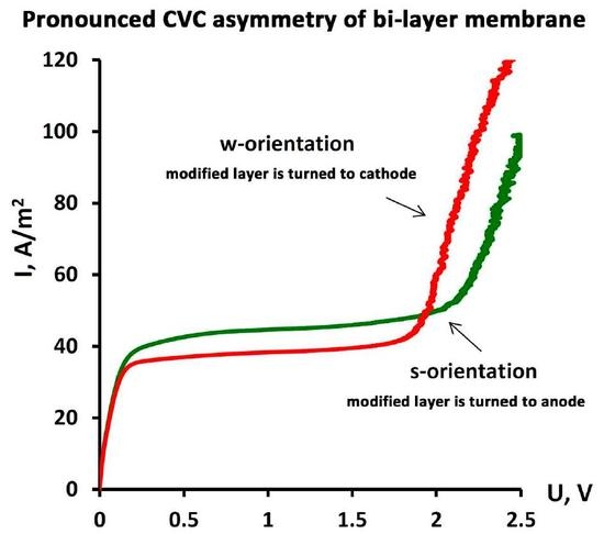
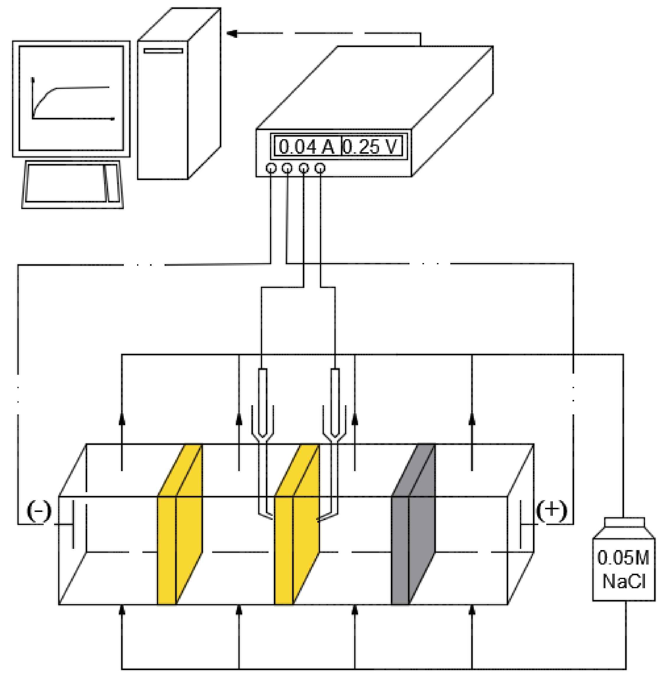
3.2. Current–Voltage Curves Measurement
4. Theory
4.1. Extraction of Physicochemical Parameters for Membrane Layers
4.2. Calculation of Limiting Currents for Different Membrane Orientations
5. Results and Discussion
6. Conclusions
Acknowledgments
Author Contributions
Conflicts of Interest
Notation List
| Latin | |
| C0, C0+, C0– | electrolyte and ion concentrations |
| D | diffusion coefficient of the electrolyte molecule in dilute solution |
| diffusion coefficients of the electrolyte molecule inside i-layer | |
| F | Faraday constant |
| hi | thickness of i-layer |
| h = h1 + h2 | thickness of the membrane |
| H = h2/h1 | ratio of membrane layer thicknesses |
| I, i | dimension and dimensionless current density |
| and | dimension and dimensionless values of the limiting current densities |
| jm | transmembrane flux density of electrolyte |
| P | coefficient of the integral diffusion permeability |
| R | universal gas constant |
| T | absolute temperature |
| U, u | dimension and dimensionless voltage |
| Greek | |
| δ | thickness of diffusion layers adjacent to both membrane surfaces |
| Δ = δ/(h1 + h2) | dimensionless thickness of diffusion layers |
| ΔU | voltage difference |
| ΔI | current density difference |
| equilibrium distribution coefficients of the electrolyte molecule and individual ions inside membrane i-layer | |
| dimensionless physicochemical parameters | |
| dimension and dimensionless i-layer exchange capacity | |
| effective dimensionless i-layer exchange capacity | |
| dimensionless normalized sum of ions concentration on the right side of the interface between two membrane layers | |
| Superscripts | |
| s, w | related to a membrane oriented by modified layer to solution and water, respectively |
| Subscripts | |
| i | related to membrane layer number i |
| m | related to a membrane |
| s, w | related to a membrane oriented by modified (1-st) layer to solution (anode) and water (cathode), respectively |
| lim | related to the limiting current regime |
| ohm | related to the ohmic part of CVC |
| overlim | related to the overlimiting current regime |
References
- Kreuer, K.D. Ion conducting membranes for fuel cells and other electrochemical devices. Chem. Mater. 2013, 26, 361–380. [Google Scholar] [CrossRef]
- Pourcelly, G.; Nikonenko, V.V.; Pismenskaya, N.D.; Yaroslavtsev, A.B. Ionic interactions in natural and synthetic macromolecules. In Applications of Charged Membranes in Separation, Fuel Cells, and Emerging Processes; John Wiley & Sons, Inc.: Hoboken, NJ, USA, 2012; pp. 761–816. ISBN 9780470529270. [Google Scholar]
- Kononenko, N.; Nikonenko, V.; Grande, D.; Larchet, C.; Dammak, L.; Fomenko, M.; Volfkovich, Y. Porous structure of ion exchange membranes investigated by various techniques. Adv. Colloids Interface Sci. 2017, 246, 196–216. [Google Scholar] [CrossRef] [PubMed]
- Izquierdo-Gil, M.A.; Barragan, V.M.; Villaluenga, J.P.G.; Godino, M.P. Water uptake and salt transport through Nafion cation-exchange membranes with different thicknesses. Chem. Eng. Sci. 2012, 72, 1–9. [Google Scholar] [CrossRef]
- Wang, J.H.; Zhang, X.G.; Zhang, B.; Zhao, Y.F.; Zhai, R.; Liu, J.D.; Chen, R.F. Rapid adsorption of Cr (VI) on modified halloysite nanotubes. Desalination 2010, 259, 22–28. [Google Scholar] [CrossRef]
- Lvov, Y.; Wang, W.; Zhang, L.; Fakhrullin, R. Halloysite Clay Nanotubes for Loading and Sustained Release of Functional Compounds. Adv. Mater. 2016, 28, 1227–1250. [Google Scholar] [CrossRef] [PubMed]
- Lvov, Y.; Abdullayev, E. Functional polymer–clay nanotube composites with sustained release of chemical agents. Prog. Polym. Sci. 2013, 38, 1690–1719. [Google Scholar] [CrossRef]
- Rawtani, D.; Agrawal, Y.K. Multifarious applications of halloysite nanotubes: A review. Rev. Adv. Mater. Sci. 2012, 30, 282–295. [Google Scholar]
- Abdullayev, E.; Sakakibara, K.; Okamoto, K.; Wei, W.; Ariga, K.; Lvov, Y. Natural Tubule Clay Template Synthesis of Silver Nanorods for Antibacterial Composite Coating. ACS Appl. Mater. Interfaces 2011, 3, 4040–4046. [Google Scholar] [CrossRef] [PubMed]
- Zhang, Y.; He, X.; Ouyang, J.; Yang, H. Palladium nanoparticles deposited on silanized halloysite nanotubes: Synthesis, characterization and enhanced catalytic property. Sci. Rep. 2013, 3, 2948. [Google Scholar] [CrossRef] [PubMed]
- Wang, R.; Jiang, G.; Ding, Y.; Wang, Y.; Sun, X.; Wang, X.; Chen, W. Photocatalytic activity of heterostructures based on TiO2 and halloysite nanotubes. ACS Appl. Mater. Interfaces 2011, 3, 4154–4158. [Google Scholar] [CrossRef] [PubMed]
- Du, M.; Guo, B.; Jia, D. Newly emerging applications of halloysite nanotubes: A review. Polym. Int. 2010, 59, 574–582. [Google Scholar] [CrossRef]
- Liu, M.; Jia, Z.; Jia, D.; Zhou, C. Recent advance in research on halloysite nanotubes-polymer nanocomposite. Prog. Polym. Sci. 2014, 39, 1498–1525. [Google Scholar] [CrossRef]
- Filippov, A.; Afonin, D.; Kononenko, N.; Lvov, Y.; Vinokurov, V. New approach to characterization of hybrid nanocomposites. Colloids Surf. A Physicochem. Eng. Asp. 2017, 521, 251–259. [Google Scholar] [CrossRef]
- Filippov, A.N.; Kononenko, N.A.; Afonin, D.S.; Vinokurov, V.A. Synthesis and prediction of transport properties of hybrid bilayer ion-exchange membranes. Surf. Innov. 2017, 5, 130–137. [Google Scholar] [CrossRef]
- Filippov, A.N.; Starov, V.M.; Kononenko, N.A.; Berezina, N.P. Asymmetry of diffusion permeability of bi-layer membranes. Adv. Colloid Interface Sci. 2008, 139, 29–44. [Google Scholar] [CrossRef] [PubMed]
- Filippov, A.N. Asymmetry of current-voltage characteristics: Bilayer model of a modified ion-exchange membrane. Colloids J. 2016, 78, 397–406. [Google Scholar] [CrossRef]
- Filippov, A.; Khanukaeva, D.; Afonin, D.; Skorikova, G.; Ivanov, E.; Vinokurov, V.; Lvov, Y. Transport Properties of Novel Hybrid Cation-Exchange Membranes on the Base of MF-4SC and Halloysite Nanotubes. J. Mater. Sci. Chem. Eng. 2015, 3, 58–65. [Google Scholar] [CrossRef]
- Filippov, A. Synthesis and Prediction of Transport Properties of Hybrid Ion-Exchange Membranes for Using in Fuel Cells and Sensors. In Proceedings of the 13th National Congress on Theoretical and Applied Mechanics, Sofia, Bulgaria, 6–10 September 2017; pp. 1–3. [Google Scholar]
- Berezina, N.P.; Kononenko, N.A.; Dyomina, O.A.; Gnusin, N.P. Characterization of Ion-Exchange Membrane Materials: Properties vs Structure. Adv. Colloids Interface Sci. 2008, 139, 3–28. [Google Scholar] [CrossRef] [PubMed]
- Kolechko, M.V.; Filippov, A.N.; Shkirskaya, S.A.; Timofeev, S.V.; Berezina, N.P. Synthesis and Diffusion Permeability of MF-4SK/Polyaniline Composite Membranes with Controlled Thickness of the Modified Layer. Colloids J. 2013, 75, 289–296. [Google Scholar] [CrossRef]
- Filippov, A.N.; Safronova, E.Y.; Yaroslavtsev, A.B. Theoretical and experimental investigation of diffusion permeability of hybrid MF-4SC membranes with silica nanoparticles. J. Membr. Sci. 2014, 471, 110–117. [Google Scholar] [CrossRef]
- Rubinstein, I.; Zaltzman, B. Equilibrium Electroconvective Instability. Phys. Rev. Lett. 2015, 114, 114502. [Google Scholar] [CrossRef] [PubMed]
- Rubinstein, I. Electroconvection at an Electrically Inhomogeneous Permselective Interface. Phys. Fluids A 1991, 3, 2301–2309. [Google Scholar] [CrossRef]


| Bi-Layer Membrane | Thickness, h, μm | Thin Layer (1) | Thick Layer (2) |
|---|---|---|---|
| No. 1 | 221 | MF-4SC modified with 4 wt % of halloysite nanotubes encapsulated by 2 wt % platinum nanoparticles | Pristine MF-4SC membrane |
| No. 2 | 181 | MF-4SC modified with 4 wt % of halloysite nanotubes | Pristine MF-4SC membrane |
| No. 3 | 166 | MF-4SC modified with 4 wt % of halloysite nanotubes encapsulated by 2 wt % platinum nanoparticles | MF-4SC membrane modified with 4 wt % of halloysite nanotubes |
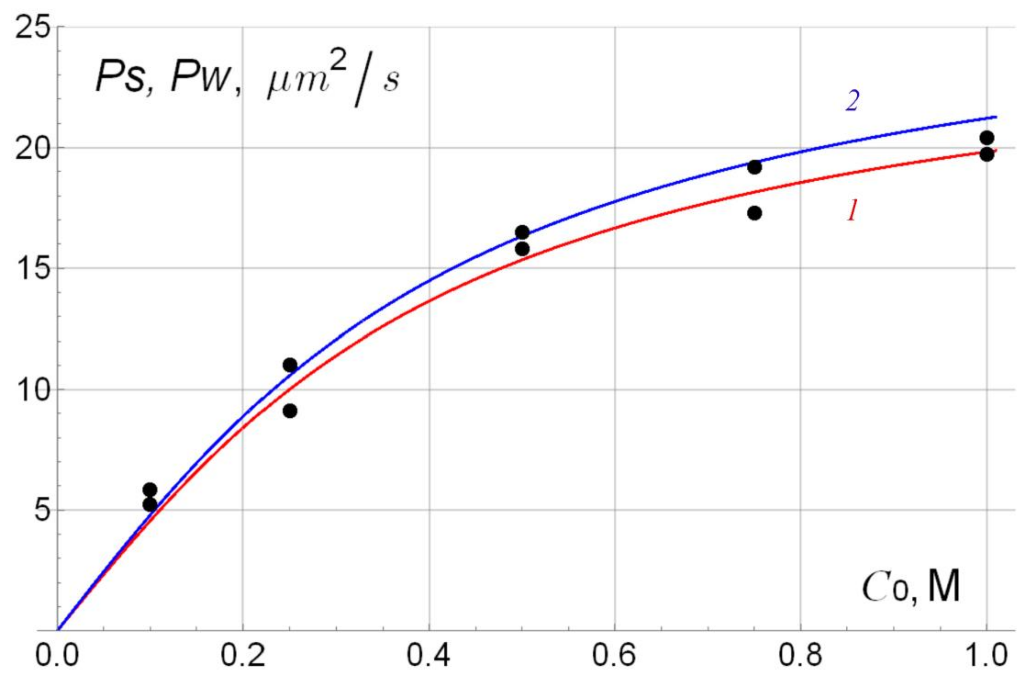
| С0 M | Ps/Pw, μm2/s, P/P + H + Pt Bi-Layer Membrane No. 1 | Ps/Pw, μm2/s, P/P + H Bi-Layer Membrane No. 2 | Ps/Pw, μm2/s, P + H/P + H + Pt Bi-Layer Membrane No. 3 |
|---|---|---|---|
| 0.1 | 5.92/6.30 | 5.84/5.23 | 4.38/5.13 |
| 0.25 | 9.73/10.9 | 9.12/11.0 | 8.69/8.40 |
| 0.5 | 15.5/14.4 | 15.8/16.5 | 13.8/13.5 |
| 0.75 | 17.8/19.7 | 17.3/19.2 | 14.7/15.5 |
| 1.0 | 20.8/21.9 | 20.4/19.7 | 16.9/17.7 |
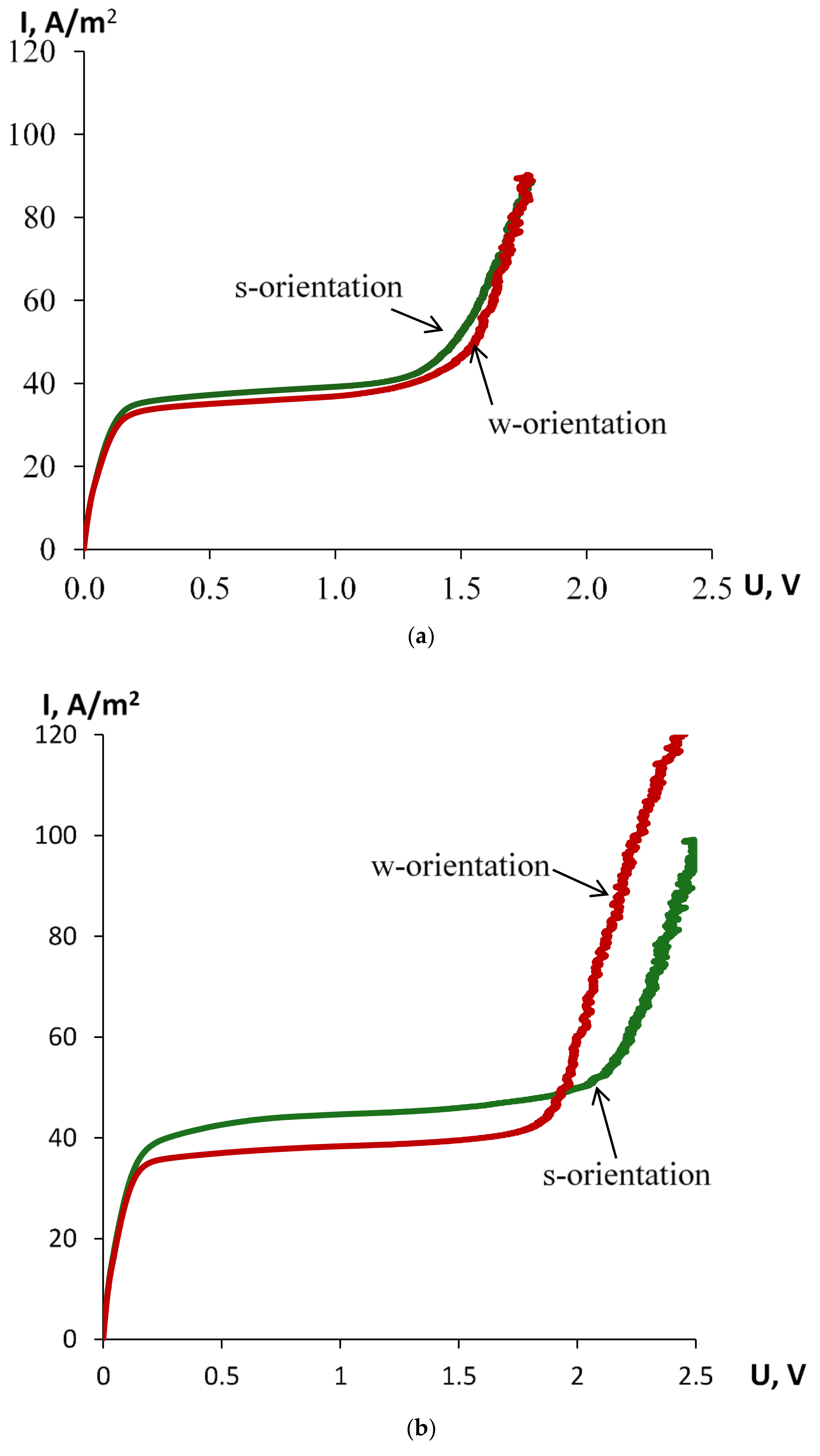
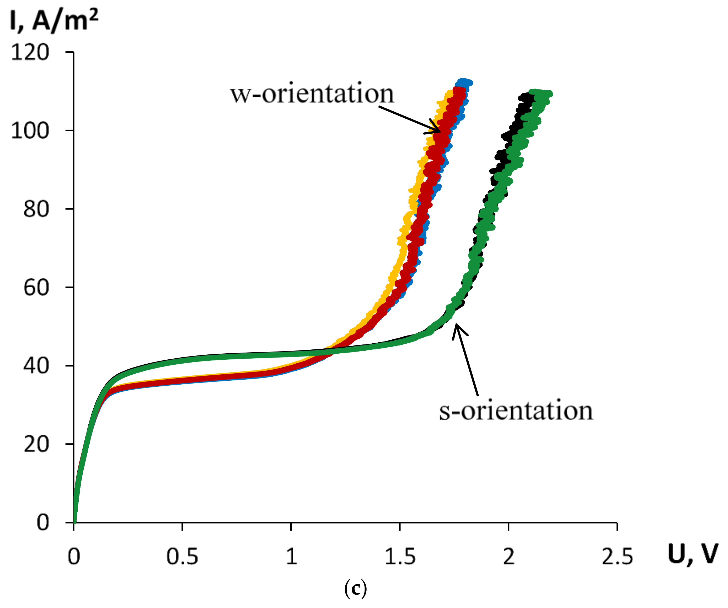
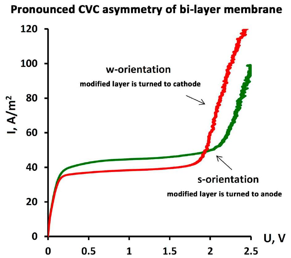
| Orientation towards Anode by | Ilim, A/m2 | ΔU, V | Slope of the Ohmic Part (ΔI/ΔU)ohm | Slope of the Limiting Part (ΔI/ΔU)lim | Slope of the Overlimiting Part (ΔI/ΔU)overlim |
|---|---|---|---|---|---|
| Membrane No. 1 | |||||
| thinner layer 1 | 35.79 ± 0.49 | 1.34 ± 0.01 | 347.0 ± 0.1 | 4.51 ± 0.01 | 158.7 ± 16.8 |
| thicker layer 2 | 33.57±1.32 | 1.42 ± 0.01 | 383.0 ± 0.2 | 3.94 ± 0.12 | 194.5 ± 5.2 |
| Membrane No. 2 | |||||
| thinner layer 1 | 42.02 ± 0.22 | 2.02 ± 0.01 | 337.6 ± 0.1 | 2.70 ± 0.01 | 135.2 ± 4.3 |
| thicker layer 2 | 35.99 ± 0.02 | 1.75 ± 0.01 | 314.6 ± 0.1 | 2.52 ± 0.00 | 153.2 ± 10.2 |
| Membrane No. 3 | |||||
| thinner layer 1 | 40.40 ± 0.16 | 1.57 ± 0.03 | 317.7 ± 0.1 | 3.14 ± 0.00 | 148.2 ± 21.5 |
| thicker layer 2 | 34.38 ± 0.54 | 1.27 ± 0.03 | 318.7 ± 0.1 | 4.85 ± 0.00 | 180.7 ± 0.1 |
| Bi-Layer Membrane | ρ1γm1, M | ρ2γm2, M | Dm1/γm1, μm2/s | Dm2/γm2, μm2/s |
|---|---|---|---|---|
| No. 1 (P/P + H + Pt), h = 221 μm | 0.545 | 0.569 | 10.54 | 44.94 |
| No. 2 (P/P + H), h = 181 μm | 0.555 | 0.569 | 10.43 | 44.94 |
| No. 3 (P + H/P + H + Pt), h = 166 μm | 0.480 | 0.527 | 8.42 | 35.88 |
| Bi-Layer Membrane | ρ1, mole/L | ρ2, mole/L | Dm1, μm2/s | Dm2, μm2/s | γm1 | γm2 |
|---|---|---|---|---|---|---|
| No. 1 (P/P + H + Pt), h = 221 μm | 1.22 | 1.08 | 4.71 | 23.68 | 0.447 | 0.527 |
| No. 2 (P/P + H), h = 181 μm | 1.15 | 1.08 | 5.04 | 23.68 | 0.483 | 0.527 |
| No. 3 (P + H/P + H + Pt), h = 166 μm | 1.22 | 1.15 | 3.31 | 16.44 | 0.393 | 0.458 |
| Bi-Layer Membrane | h, μm | δs/δideal, μm | δw/δideal, μm | ||
|---|---|---|---|---|---|
| s-Orientation | w-Orientation | ||||
| No. 1 (P/P + H + Pt), | 221 | 464/365 = 1.27 | 1.011 ± 0.014 | 594/388 = 1.53 | 0.948 ± 0.037 |
| No. 2 (P/P + H), | 181 | 394/310 = 1.27 | 0.972 ± 0.005 | 558/361 = 1.55 | 0.833 ± 0.001 |
| No. 3 (P + H/P + H + Pt), | 166 | 415/323 = 1.28 | 0.857 ± 0.003 | 586/380 = 1.54 | 0.729 ± 0.012 |
© 2018 by the authors. Licensee MDPI, Basel, Switzerland. This article is an open access article distributed under the terms and conditions of the Creative Commons Attribution (CC BY) license (http://creativecommons.org/licenses/by/4.0/).
Share and Cite
Filippov, A.; Petrova, D.; Falina, I.; Kononenko, N.; Ivanov, E.; Lvov, Y.; Vinokurov, V. Transport Asymmetry of Novel Bi-Layer Hybrid Perfluorinated Membranes on the Base of MF-4SC Modified by Halloysite Nanotubes with Platinum. Polymers 2018, 10, 366. https://doi.org/10.3390/polym10040366
Filippov A, Petrova D, Falina I, Kononenko N, Ivanov E, Lvov Y, Vinokurov V. Transport Asymmetry of Novel Bi-Layer Hybrid Perfluorinated Membranes on the Base of MF-4SC Modified by Halloysite Nanotubes with Platinum. Polymers. 2018; 10(4):366. https://doi.org/10.3390/polym10040366
Chicago/Turabian StyleFilippov, Anatoly, Daria Petrova, Irina Falina, Natalia Kononenko, Evgenii Ivanov, Yuri Lvov, and Vladimir Vinokurov. 2018. "Transport Asymmetry of Novel Bi-Layer Hybrid Perfluorinated Membranes on the Base of MF-4SC Modified by Halloysite Nanotubes with Platinum" Polymers 10, no. 4: 366. https://doi.org/10.3390/polym10040366
APA StyleFilippov, A., Petrova, D., Falina, I., Kononenko, N., Ivanov, E., Lvov, Y., & Vinokurov, V. (2018). Transport Asymmetry of Novel Bi-Layer Hybrid Perfluorinated Membranes on the Base of MF-4SC Modified by Halloysite Nanotubes with Platinum. Polymers, 10(4), 366. https://doi.org/10.3390/polym10040366