Article

Sensing Characteristics of Side-Polished Fiber Based on the Alterations in Helical Structure of Thermo-Sensitive Cholesteric Liquid Crystals

1
Guangdong Vocational College of Post and Telecom, Guangzhou 510630, China
2
School of Network and Continuing Education, Beijing University of Posts and Telecommunications, Beijing 510630, China
3
China Tower Corporation Limited Guangdong Branch, Guangzhou 510000, China
*
Author to whom correspondence should be addressed.
Crystals 2019, 9(9), 465; https://doi.org/10.3390/cryst9090465
Submission received: 19 July 2019 / Revised: 30 August 2019 / Accepted: 1 September 2019 / Published: 5 September 2019
(This article belongs to the Special Issue Advances in Cholesteric Liquid Crystals)

Abstract

:
Cholesteric liquid crystals (CLCs) are sensitive to environmental temperature changes, and have been employed as a specific intermediary for biosensors. Considering the temperature-dependent structural changes of CLCs, this study aimed to determine the sensing properties of side-polished fibers (SPFs) after coating with CLCs. The experimental results demonstrated that, with regard to the transmitted spectrum, the loss peak of CLC-coated SPFs exhibited a positive linear relationship with temperature changes over a range of 20 to 50 °C. The linear correlation coefficient achieved 97.8% when the temperature increased by 10 °C, and the loss peak drifted by 12.72 nm. The reflectance spectrum of CLCs coated on the polished surface were obtained using optical fiber sensors. The feasibility of measuring the helical structure of CLCs was further verified using SPF transmission spectroscopy. The findings indicated that the transmitted spectrum of SPFs could be adopted to characterize the helical structure of CLCs, which lays a solid foundation for further study on SPF-based biosensors.

1. Introduction

Cholesteric liquid crystals (CLCs) with orientational order are capable of undergoing liquid to solid phase transition. They exhibit both liquid fluidity and crystal anisotropy, which lie primarily in optical anisotropy, such as birefringence. In addition to optical anisotropy, CLCs display a selective reflection of light due to their periodic helical structure. The selective reflection properties of CLCs have been shown to be associated with their helical pattern. The intrinsic pitch of the thermos-sensitive CLC selected in this study was the same as the wavelength of visible light. When the spiral axis of CLC is perpendicular to the substrate surface, the Bragg reflection of visible light can appear. The helical structure of CLCs is not only related to its material properties but is also a sensitive function of temperature, electromagnetic field, acoustic field, radiation field, and even biochemical sensing. Therefore, CLCs have been widely applied in sensor fields, especially biosensors [1,2,3,4,5,6,7]. The liquid crystalline state has become ubiquitously recognized in organisms, in which the helical structure of amphiphilic lipids from the plasma membrane is a natural composition containing a lyotropic liquid crystal structure. Collagen and organismal DNA may synthesize CLCs with a helical or double helical structure through self-assembly [8]. However, the most commonly employed methods for characterizing CLCs in biosensors are polarized light microscopy [8], differential scanning calorimetry, X-ray diffraction, atomic force microscopy, Fourier-transform infrared spectroscopy, circular dichroism spectroscopy, nuclear magnetic resonance, and small-angle neutron scattering [8]. By examining the transmittance and texture alterations of liquid crystal molecules under a polarizing microscope, the phase transition of CLCs can be analyzed, as well as the morphological variables, such as changes in texture and orientation. However, in view of practical applications, it is rather difficult to accurately and comprehensively characterize the liquid crystal state, regardless of the unavailability of miniaturized analytical equipment. Thus, inevitably, the quantification of the measurement data must be done focally by using micro-point probes, rather than real-time monitoring of changes in CLCs [9,10,11].
Optical fiber sensors, especially those with evanescent wave absorption, have already been applied in the field of biomedical sensing research [12,13,14]. Side-polished fiber (SPF) is a specific optical fiber made by removing part of the cladding from standard optical fibers through optical microfabrication technology [15,16,17]. A variety of new optical devices and sensors have been fabricated by coating with liquid crystals on their polished surfaces. Several studies have [18,19] proposed that azobenzene polymer can be introduced to the nematic liquid crystal and coated on the polished surface of SPF, through which an optically controllable SPF attenuator is made based on the liquid crystals. However, Yu et al. [20,21] coated the mixed liquid crystals onto the side-polished surface of SPF and managed to fabricate an optically powered fiber optic sensor. Tang et al. [22] successfully fabricated optical fiber-based volatile organic compound gas sensors by coating CLCs onto the polished surface of SPFs. In addition to the advantages of small volume, low cost, anti-electromagnetic interference, and being easily accessible and reusable, SPFs are sensitive to external environmental factors. This is probably because the optical field in the core leaks out through the polished surface in the form of an evanescent wave, which makes it possible to interact with the external environmental factors. Therefore, SPF is not only sensitive to the external environmental changes but also has adjustable length and depth. SPFs often exhibit longer operating distances or larger surfaces, and thus they tend to have relatively higher sensitivity. According to the findings of previous experiments, we hypothesize that the orientational changes in nematic liquid crystals can be characterized by SPF-transmitted optical power [23].
In this study, the sensing properties of SPFs based on the helical structure changes of thermos-sensitive CLCs were investigated within the visible light range. The reflection spectra of thermos-sensitive CLCs coated upon the polished surface were measured using an optical fiber reflection probe, while the transmitted spectra of SPFs were used to characterize the temperature-induced structural changes of CLCs. The findings provide the feasibility of measuring the helical structure changes of CLCs by SPF via transmission spectroscopy, as well as laying a foundation for future research on CLC-coated SPF biosensor.

2. Materials and Methods

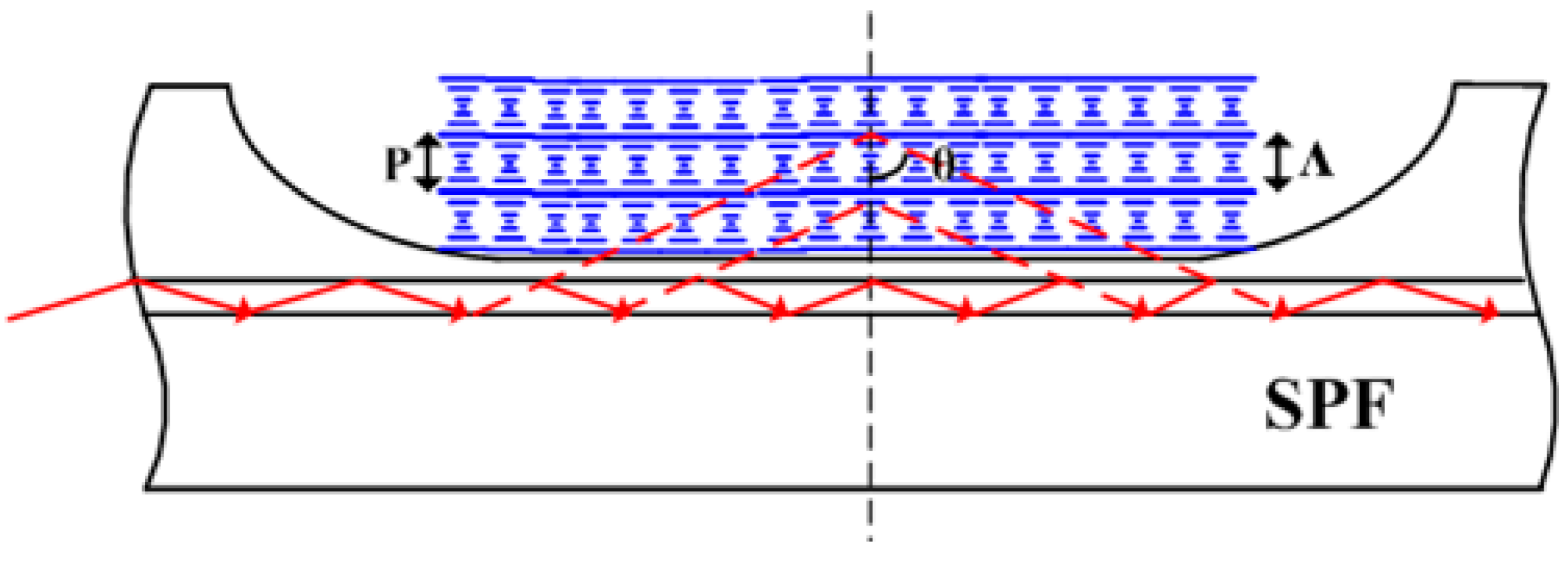
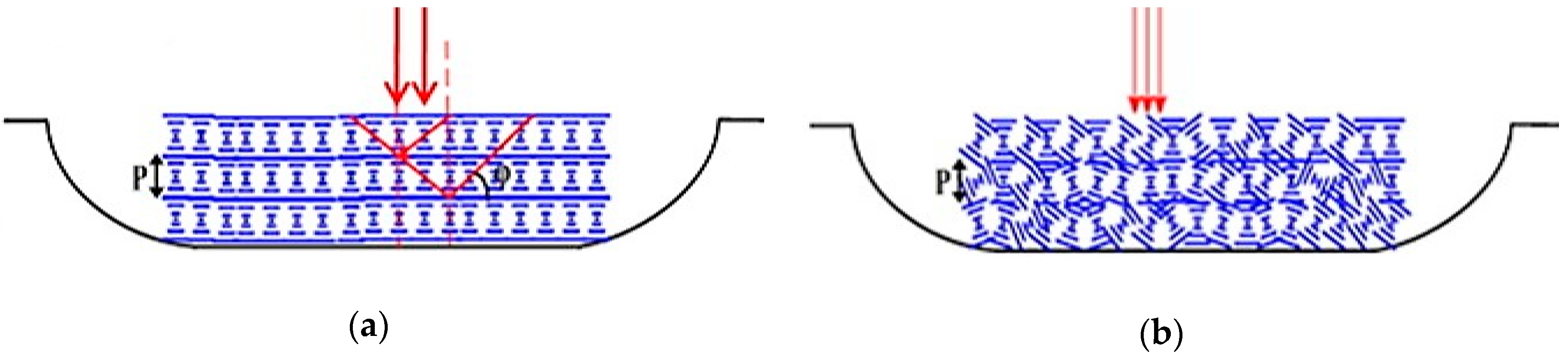
2.1. Experimental Design

CLCs has been recognized as chiral nematic liquid crystals. Chirality refers to the ability to selectively reflect a certain portion of circular polarization. The CLC molecules exhibit a uniform alignment of their direction in a single layer and accumulated layer by layer. The directional vectors of each layer are slightly deviated from those of the adjacent layer, thereby forming a helical structure. The helical axis of CLC is perpendicular to n ¯ , which corresponds to the optical axis. Under a 360° rotation along the helical direction, its long axis returns to the initial orientation. The pitch (periodic interval between layers) of CLC is an important parameter for determining its helical structure. CLCs demonstrate the characteristics of reflecting visible light with one pitch, which is strongly dependent on temperature changes and external environmental factors.
Hence, the experimental design of this study was focused on CLCs (5 μL) coated on the polished surface of SPFs. The intrinsic pitch of cholesterol ester liquid crystal selected in this study was equivalent to the wavelength of visible light. The helical structure of cholesterol ester liquid crystals may change in response to increasing temperatures, and disappear upon reaching isotropy [24,25,26]. Considering the temperature-sensitive structural changes of CLCs, the sensing response characteristics of SPFs were evaluated. Through optical fiber sensing, the ambient temperature-induced alterations in the reflective spectrum of CLCs were determined, and the relationship between its reflective spectrum and the helical structure was examined. Moreover, the characteristics of the transmission spectrum of SPFs in response to the ambient temperature-induced structural changes of CLCs were examined. Additionally, the transmission spectrum of SPFs was used to verify the feasibility of measuring the structural changes of CLCs.

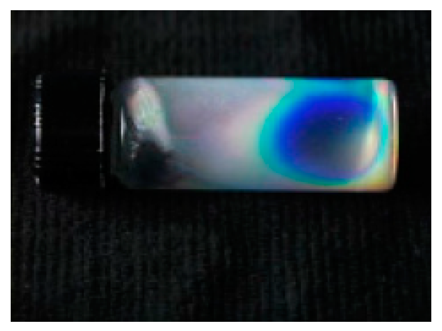
2.2. Preparation of CLCs

CLCs are sensitive to the changes in environmental temperature and are often displayed as bright colors. In addition, they are relatively similar to proteins with respect to the spatial uniformity of their helical structures. The temperature sensitivity range of liquid crystals can be adjusted by mixing different types of formulations. This experimental design was based on the studies of Brown et al. [24] and Elser et al. [25]. Specifically, cholesteryl oleyl carbonate (15, 115-7; Sigma-Aldrich), cholesteryl pelargonate (C7, 880-1; Sigma-Aldrich), and cholesteryl benzoate (C7, 580-2; Sigma-Aldrich) were used to prepare the temperature-sensitive cholesterol ester liquid crystals. The preparation procedure was as follows. First, 0.38, 0.52, and 0.10 g of cholesterol carbonate, cholesterol nonyl ester, and cholesterol benzoate, were, respectively, mixed in a glass bottle. Next, the tube bottle was heated by a hot air cylinder until all the powdered solid samples were melted into a transparent liquid. Subsequently, the melted liquid sample was placed in an ultrasonic cleaner, and uniformly homogenized at 40 °C for 10 minutes. After ultrasound homogenization, the sample was transferred onto a tube mixer and oscillated for 10 minutes, to completely mix it again. Thereafter, the sample was statically cooled at room temperature, and the visualized color was recorded (Figure 1).

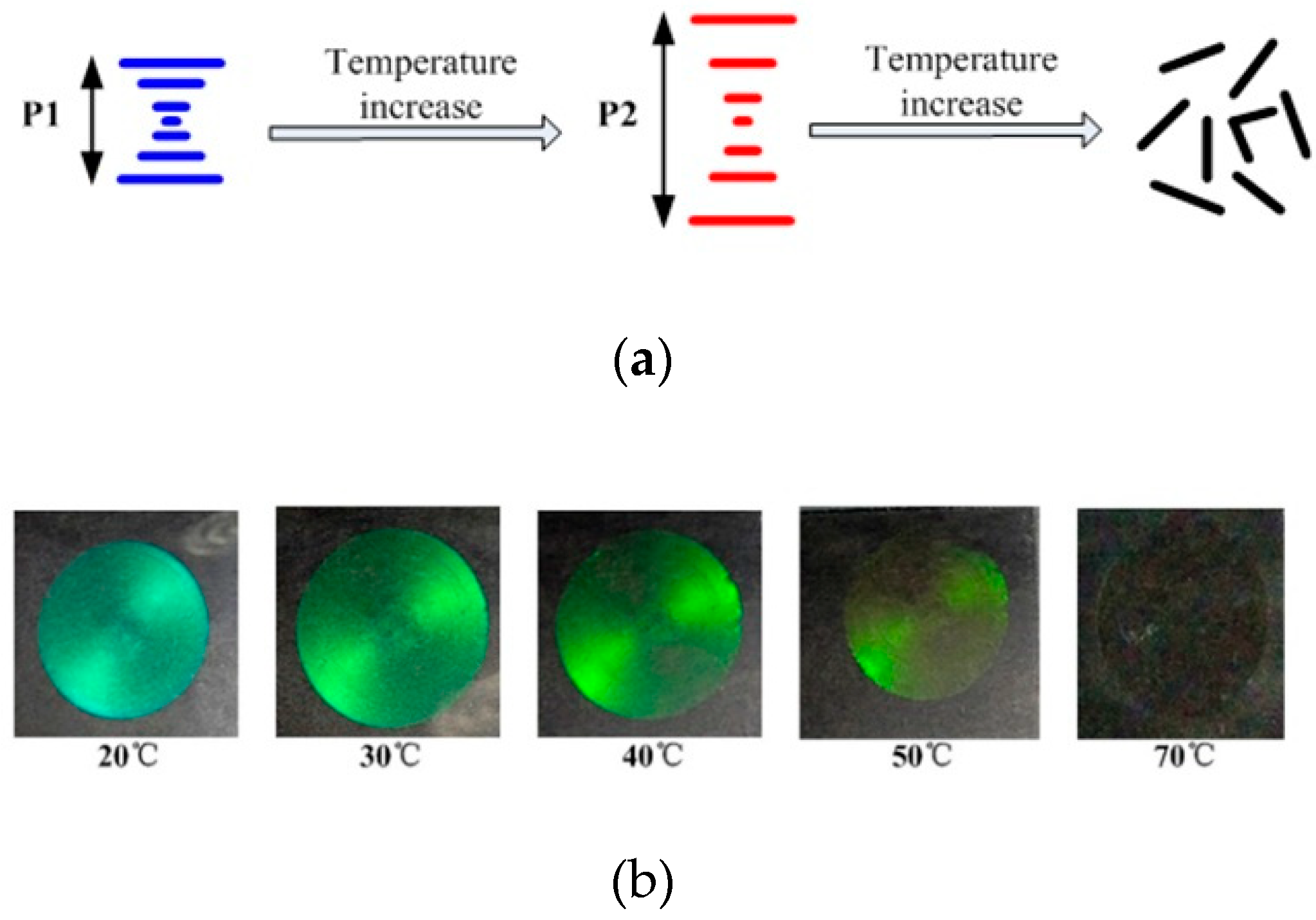
2.3. Thermosensitivity of CLCs

The homochiral helical structure of CLCs allows the Bragg reflection of visible light when the helical axis of the liquid crystals is perpendicular to the substrate (Figure 2). Typically, CLCs can exert the strongest selective reflection on the wavelengths of the incident light only if the light is incident along the spiral axis of liquid crystals. The formula for reflection wavelength (λo) is shown as follows:
λ 0 = n ¯ p
where, n ¯ is the equivalent refractive index of the CLC. Thus, the selective reflection properties of CLCs are related to their helical structures.
The helical structures of CLCs can be altered in response to high temperature [25]. According to Formula (1), the reflection wavelength λ0 could drift, while the colors of reflected light varied with the increasing temperatures (Figure 3b). The liquid crystalline form of cholesteryl ester was blue–green in color at room temperature (~20 °C), but turned green–yellow, after being heated to 50 °C. The liquid crystal of cholesteryl ester transited from the anisotropic phase to the isotropic phase. Specifically, its spiral structure disappeared after being heated to 70 °C, and it achieved isotropy and displayed as a transparent liquid. The helical structure of CLCs can be confirmed by the wavelength-selective reflection from CLCs. The wavelength-selective reflection arises from the Bragg reflection with the periodic helical structure in CLCs. According to the Bragg reflection, when the incident light illuminates the CLC film vertically, the light at the wavelength λ0 will be reflected while the light at other wavelength transmits [18]. Therefore, the helical structure of CLCs may react to environmental temperature changes and appears to be quite sensitive.

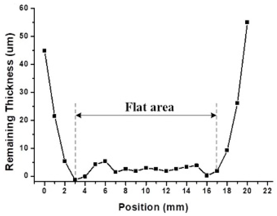
2.4. Preparation of SPFs

In the present study, the wheel side-polishing technique was employed for the preparation of single-mode optical fibers (SMF-28e single-mode ordinary communication optical fibers, Corning Company) [16]. The SPFs used in this experiment were prepared by polishing twice. The transmission power of SPFs was 2.2 dBm before polishing, and −2.3 dBm after polishing. The residual thickness of the SPF was obtained by measuring the side surface of the SPF using a microscope at 10× magnification. During microscopic measurements, the mechanistic platform of the microscope was moved along the axis of SPFs in steps of 1.0 mm, and a series of images were taken at different positions of SPFs. As shown in Figure 4a,c are transitional zones at both ends of the SPF, while (b) is a flat zone in the middle. The length of the polished surface and average residual thickness of the SPF were found to be ~20 mm and ~2 μm, respectively (Figure 5).

2.5. Reflection Spectrum Measurement of CLCs

The CLC layer coated on the surface of SPFs was regarded as the Bragg reflection structure with liquid crystal pitch as its period. The maximum reflection wavelength was calculated according to the following formula:
λ 0 = 2 n C L C Λ = 2 n C L C p ,
where nCLC is the effective refractive index of the cladding of CLC under Bragg reflection waveguide structure, Λ is the time period of Bragg waveguide, and p is the pitch of CLC. Given that CLCs are temperature sensitive, its helical structures could be altered in response to increasing temperatures. Therefore, raising the temperature might shift the maximum reflection wavelength satisfying the Bragg reflection.

2.6. Transmission Spectrum Measurement of SPFs

The SPF used in our study was made from a single mode fiber using the wheel-polishing method. In a step-index fiber with a circular cross-section, the refractive index of a fiber’s core, nco, is greater than that of its cladding, ncl, and the fiber mode effective index, neff, lies between nco and ncl. In the case of the SPF having a D-shaped cross-section, the cladding between the core and the polished surface can be made to be sufficiently thin to allow the evanescent field to extend into the external medium above the polished surface of the SPF. If the polished surface of the SPF is coated with a material with refractive index, nCLC, the mode effective index of the SPF/external material medium structure will depend on the cladding thickness and the value of the nCLC. According to the theoretical analysis on optical propagation characteristics of SPF shown in reference [15] and [16], when nCLC < neff, there is total internal reflection and the loss of light propagating in SPF is the minimum. When nCLCneff, the fiber mode becomes leaky, and power can be radiated out of the core of the fiber. On this occasion, the loss of light propagating in the SPF is the maximum due to the guided mode changing to radiation mode. When nCLC > neff, there is semi-reflection and part of light leaks. The loss of light propagating in an SPF can, therefore, be very dependent on the value of the nCLC.
The transmitted light on the SPF was incident to the Bragg reflection from the CLC at an angle of θ. Because the evanescent field leaked from the SPF core, the light wave from the CLC was reflected back to the side-polished optical fiber for the purpose of light propagation (Figure 6). Therefore, the CLC coated on the polished surface of SPFs might constitute liquid–crystal waveguides cladding with a Bragg reflection structure, and its reflective wavelength was calculated as follows:
m λ 0 = 2 n C L C   p c o s θ m = 0 , 1 , 2 , 3 ...
Considering that CLCs are temperature sensitive, their spiral structure may change in response to increasing temperatures. It was speculated that the spiral axis of CLCs was perpendicular to the polished surface of SPFs, and therefore, the liquid crystal molecules were intrinsically twisted along the polished surface to form periodic helical structures (Figure 6). In addition, the reflected light waves satisfying the Bragg reflection waveguide were propagated from CLCs to SPFs, and thus the transmitted spectrum of CLC-coated SPFs drifted with the increase in temperature. Furthermore, the reflective spectra of CLCs and the transmitted spectra of SPFs were measured simultaneously, and the results were compared.

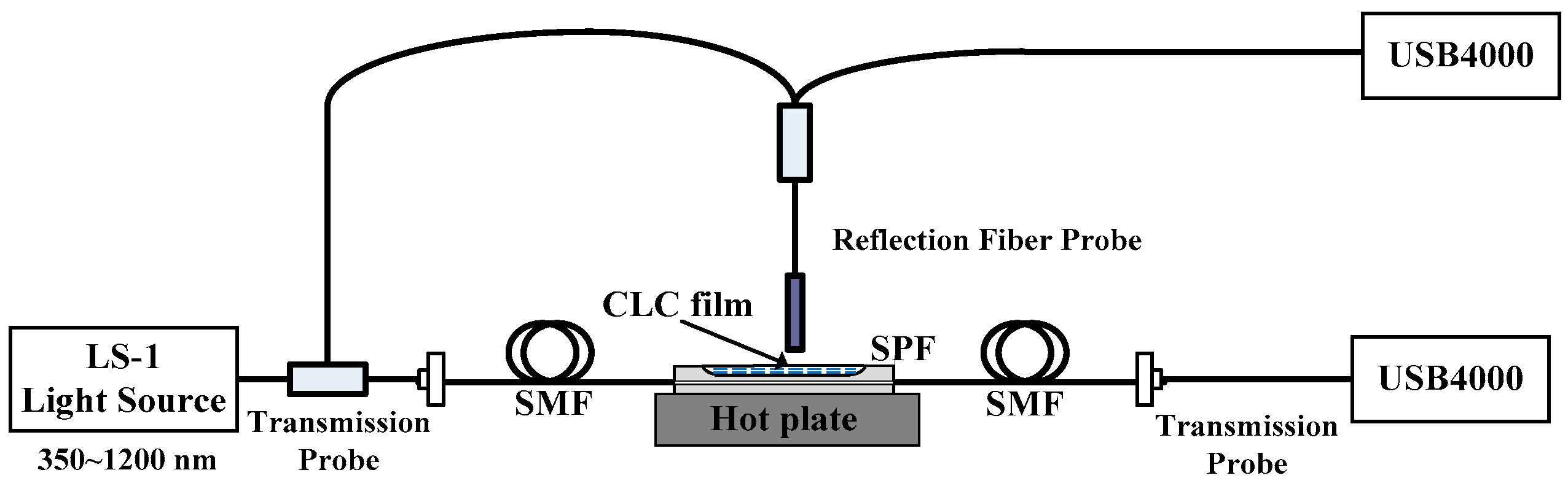
2.7. Experimental Device

The schematic diagram of the experimental device for sensing the characteristics of SPFs based on the structural changes of CLCs is illustrated in Figure 7. LS-1 provides detection light covering the visible band. The transmitted spectra of SPFs coated with CLCs on its polished surface, and the reflection spectra of liquid crystals were measured by using the transmission probe of USB4000 Spectrometer (Ocean Optics) and the optical fiber reflection probe perpendicular to CLCs. A hot plate was used to control the temperature around the polished surface of SPFs, by heating from room temperature 20 to 70 °C. Before heating, the liquid crystal was transformed into a transparent liquid, while the heat disc was adjusted to the targeted temperature. Such a process is exploited here to avoid the inhomogeneity caused by daubing and is capable of making CLCs reorient and self-assemble in order on the polished surfaces of SPFs, and thus form a more stable and homogeneous helical microstructure in the CLCs layer.

3. Results and Discussion

CLCs have a selective reflection of light, resulting from the fact that they are composed of a periodic helical structure. In this study, temperature-sensitive CLCs were uniformly coated on the polished surface of SPFs, and the sensing characteristics of SPFs were evaluated based on the structural change of CLCs.

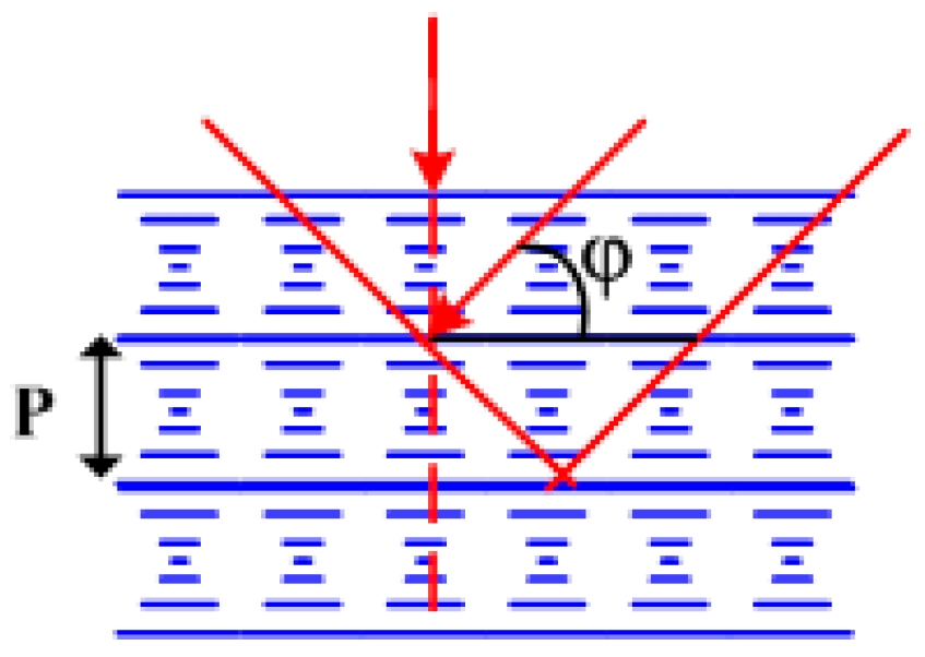
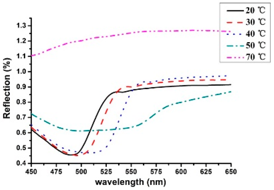
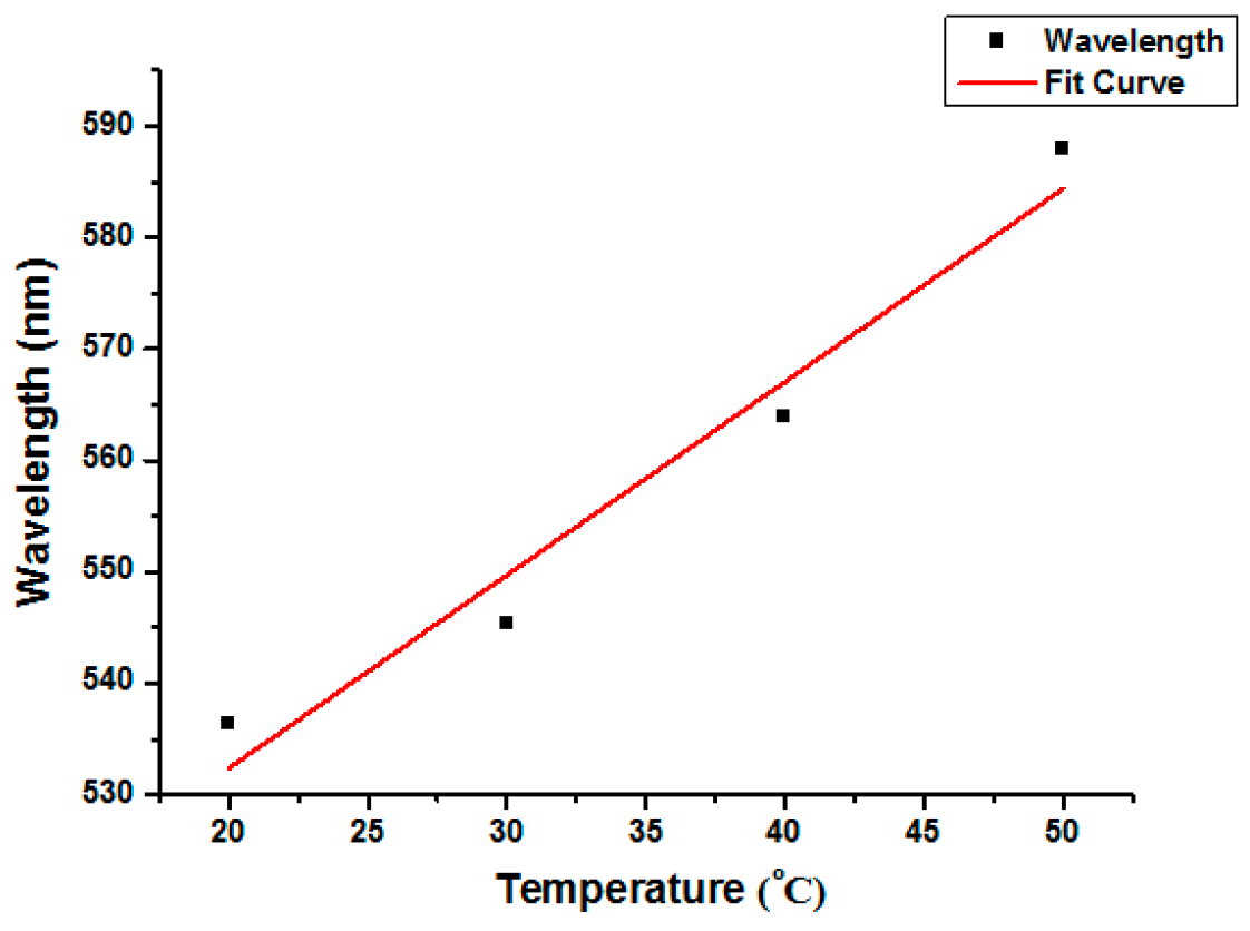
3.1. Reflection Spectra of CLCs in Response to Environmental Temperature Changes

The optical fiber reflector probe was placed vertically above the CLCs, and the light reflection was incident vertically on the coated CLC surface. When the ambient temperature around the polished surface of SPFs was increased from 20 to 50 °C at intervals of 10 °C, the maximum reflection wavelength of the CLC reflectance spectrum was shifted from 536 to 587 nm. When the temperature was raised to 70 °C, the reflection peak of CLCs disappeared (Figure 8). Formula (2) showed that the optical selective reflection properties of CLCs are related to their helical structures. The helical structures of CLCs altered with the temperature rising from 20 to 50 °C. The reflection wavelength measured by optical fiber reflector was red-shifted by approximately 50 nm. CLCs reached isotropy at the phase transition temperature of approximately 70 °C, and their periodic helical structure did not exist anymore. Within the temperature range of 20 to 50 °C, the maximum reflection wavelength of CLCs was linearly correlated with the drift of ambient temperature. The linear equation of λp = 1.7341T + 497.69 was obtained, and the linear correlation coefficient achieved 94.5% (Figure 9). These results indicated that the reflectance spectra of CLCs exhibit a good linear relationship with temperature. Notably, the maximum reflection wavelength of CLC reflectance spectra shifted 17.34 nm for every 10 °C rise in temperature. Therefore, the optical selective reflection properties of CLCs strongly support that its helical structure has a temperature-sensitive function.
For the typical case where the helix axis is perpendicular to the interface, it can be seen from Formula (2) that the measured reflection spectrum of the CLC surface may display a significant reflection peak (Figure 10a). However, in this experiment, the spiral axis of CLCs around the polished surface is not uniformly perpendicular to the interface due to the coating of CLCs on the SPF polished surface (Figure 10b). As a result, the Bragg’s reflection peaks of the CLC surface were wide, and only the corresponding wavelength at the edge of the reflection peaks was affected by temperature alterations.

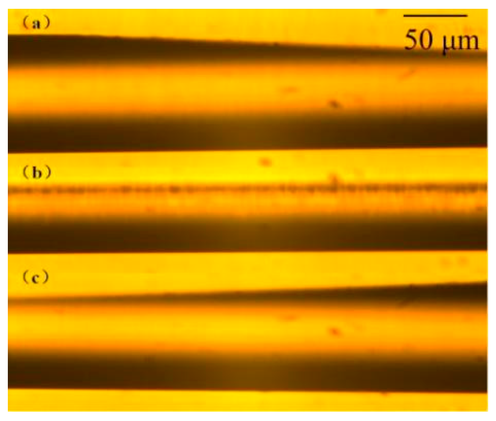
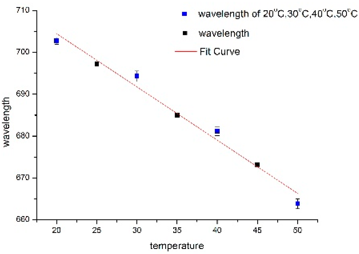
3.2. Transmission Spectra of SPFs in Response to the Structural Changes of CLCs

The transmission spectra of CLC-coated SPFs are presented in Figure 11 as a function of temperature. The transmission light in the SPFs was incident into the Bragg reflection waveguide structure composed of CLC, and the light waves satisfying the Bragg reflection could be reflected back from CLCs to SPFs to maintain propagation. To compare the transmission spectra of CLC-coated SPFs and those of CLCs alone, the loss peak (valley) of SPF transmission spectra was assessed in the present study. When the temperature was increased from 20 to 70 °C, the transmission spectra of CLC-coated SPFs blue-shifted from 702.77 to 597.8 nm, suggesting that the helical structure of CLCs changed and the long-wave band of visible light was transmitted back to SPFs in response to higher temperatures. These results were consistent with the red-shifted spectral data of CLCs (Figure 8). This indicates that the transmission spectra of SPFs can characterize the structural changes of CLCs. When the temperature reached 70 °C, the helical structure of CLCs disappeared, indicating the phase transition from liquid crystal to isotropy. The measured transmission spectrum of SPFs was different between each temperature, at which the half-width of loss transmission peak was the largest. Therefore, the transmitted spectra of SPFs can characterize the changes in the helical structure of CLCs modulated by ambient temperature.
Where the helix axis is perpendicular to the interface (Figure 10a), the transmission spectra of CLC-coated SPFs may display a significant loss peak. However, in this experiment, without the alignment of CLC, the spiral axis of CLCs around the polished surface was not uniformly perpendicular to the interface due to the coating of CLCs on SPF polished surface (Figure 10b). As a result, the Bragg’s reflection peaks of CLC surface were wide, and only the corresponding wavelength at the edge of the reflection peaks was affected by temperature alterations. Thus, the cause of many small peaks near the main peak shown as Figure 11 should be the spiral axis of CLCs adjacent to the polished surface, which was not uniformly perpendicular to the interface.
The CLCs coated on the polished surface of SPFs have a periodic helical structure within the temperature range of 20 to 50 °C. The transmitted spectrum loss peak of SPFs is based on the fact that changes in the helical structure of CLCs are a temperature-sensitive function. The linear equation λp = 1.272T + 729.891 was fitted and its linear correlation reached 97.8% (Figure 12). The results indicate that the transmitted spectrum loss peak of CLC-coated SPFs exhibits a good linear relationship with temperature. The blue-shifted transmission loss peak of SPFs was 12.72 nm for every 10 °C rise in temperature. Therefore, within the temperature range of 20 to 50 °C, SPFs, based on the spiral structure changes of CLC, can sense the alterations in environmental temperature, with relatively higher sensitivity and better linear relationship.

4. Conclusions

In conclusions, the sensing properties of CLC-coated SPFs in response to the ambient temperature-modulated structural change of CLCs were assessed in the present study. The loss peak of the transmitted spectrum pertaining to CLC-coated SPFs demonstrated a good linear relationship with temperature (ranging from 20 to 50 °C). The linear correlation coefficient achieved 97.8% when the temperature increases by 10 °C, and the loss peak drifted by 12.72 nm. At 70 °C, the half-maximum width of the loss transmission peak of CLCs reached the maximum value due to the transition from the liquid crystal phase to the isotropic phase. The maximum reflection wavelength of CLCs red-shifted 17.34 nm for every 10 °C rise in temperature, and the linear correlation coefficient achieved 94.5% at the temperature range of 20 to 50 °C. When the temperature rose to 70 °C, the reflection peak of CLCs disappeared. The optical selective reflection characteristics of CLCs well-demonstrate that its helical structure is a temperature-sensitive function, as evaluated by the transmitted spectrum analysis of SPFs. The feasibility of measuring the helical structure of CLCs by SPF transmission spectra was further verified by the reflectance spectrum of CLCs assessed by a fiber-optic reflection probe. Collectively, the transmission spectra of SPFs could be used to characterize the structural changes of CLCs, thereby laying a foundation for further investigations on CLC-coated SPF biosensors.

Author Contributions

Conceptualization, Y.H.; methodology, Y.H.; formal analysis, Y.H.; investigation, Y.H.; resources, W.G.; data curation, Y.J.; writing—original draft preparation, Y.H.; writing—review and editing, Y.H.; project administration, Y.H.

Funding

This research was funded by Fundamental Research Funds for Science and Technology Program of Guangzhou, China, grant number 201707010496; Fundamental Research Funds for Youth Innovation Personnel Training Project of Guangdong, China, grant number 2017GkQNCX042.

Acknowledgments

The authors would like to express their gratitude to EditSprings (https://www.editsprings.com/) for the expert linguistic services provided. And the authors would like to express their gratitude to Zhe Chen, Jinan University for the technical support.

Conflicts of Interest

The authors declare no conflict of interest. The funders had no role in the design of the study; in the collection, analyses, or interpretation of data; in the writing of the manuscript, or in the decision to publish the results.

References

  1. Woliński, T.R.; Bock, W.J. Cholesteric liquid crystal sensing of high hydrostatic pressure utilizing optical fibers. Mol. Cryst. Liq. Cryst. 1991, 199, 7–17. [Google Scholar] [CrossRef]
  2. Shibaev, P.V.; Schlesier, C. Distant mechanical sensors based on cholesteric liquid crystals. Appl. Phys. Lett. 2012, 101, 193503. [Google Scholar] [CrossRef]
  3. Moreira, M.F.; Carvalho, I.C.S.; Cao, W.; Bailey, C.; Taheri, B.; Palffy-Muhoray, P. Cholesteric liquid-crystal laser as an optic fiber-based temperature sensor. Appl. Phys. Lett. 2004, 85, 2691–2693. [Google Scholar] [CrossRef] [Green Version]
  4. Mitov, M. Cholesteric Liquid Crystals with a Broad Light Reflection Band. Adv. Mater. 2012, 24, 6260–6276. [Google Scholar] [CrossRef]
  5. Hennig, G.; Brittenham, G.M.; Sroka, R.; Kniebühler, G.; Vogeser, M.; Stepp, H. Bandwidth-variable tunable optical filter unit for illμmination and spectral imaging systems using thin-film optical band-pass filters. Rev. Sci. Instrum. 2013, 84, 043113. [Google Scholar] [CrossRef]
  6. Hikmet, R.A.M.; Kemperman, H. Electrically switchable mirrors and optical components made from liquid-crystal gels. Nature 1998, 392, 476–479. [Google Scholar] [CrossRef]
  7. Woltman, S.J.; Jay, G.D.; Crawford, G.P. Liquid-crystal materials find a new order in biomedical applications. Nat. Mater. 2007, 6, 929–938. [Google Scholar] [CrossRef]
  8. Hsiao, Y.C.; Sung, Y.C.; Lee, M.J.; Lee, W. Highly sensitive color-indicating and quantitative biosensor based on cholesteric liquid crystal. Biomed. Opt. Express 2015, 6, 5033–5038. [Google Scholar] [CrossRef] [Green Version]
  9. Popov, N.; Honaker, L.W.; Popova, M.; Usol’tseva, N.; Mann, E.K.; Jákli, A.; Popov, P. Thermotropic Liquid Crystal-Assisted Chemical and Biological Sensors. Materials 2017, 11, 20. [Google Scholar] [CrossRef]
  10. Brake, J.M.; Mezera, A.D.; Abbott, N.L. Active control of the anchoring of 4’-pentyl-4-cyanobiphenyl (5CB) at an aqueous-liquid crystal interface by using a redox-active ferrocenyl surfactant. Langmuir 2003, 19, 8629–8637. [Google Scholar] [CrossRef]
  11. McCamley, M.K.; Ravnik, M.; Artenstein, A.W.; Opal, S.M.; Žumer, S.; Crawford, G.P. Detection of alignment changes at the open surface of a confined nematic liquid crystal sensor. J. Appl. Phys. 2009, 105, 123504. [Google Scholar] [CrossRef]
  12. Huang, H.; Zhai, J.; Ren, B. Fiber-Optic Evanescent Wave Biosensor and Its Application. ACTA Opi. Sin. 2003, 23, 451–454. [Google Scholar]
  13. Deng, L.; Feng, Y.; Wei, L. The Research of Fiber Optic Evanescent Wave Biosensor. ACTA Photonica Sin. 2005, 34, 1688–1692. [Google Scholar]
  14. Lin, H.Y.; Tsai, W.H.; Tsao, Y.C.; Sheu, B.C. Side-polished multimode fiber biosensor based on surface plasmon resonance with halogen light. Appl. Opt. 2007, 46, 800–806. [Google Scholar] [CrossRef]
  15. Chen, Z.; Li, F.; Zhong, J. Side polished fiber and application. In Proceedings of the 12th Fiber Communication and 13th Integrated Optics Conference, Jinan University, Guangzhou, China, 2005; pp. 407–412. [Google Scholar]
  16. Chen, Z.; Cui, F.; Zeng, Y. Theoretical analysis on optical propagation characteristics of side-polished fibers. Acta Photonica Sin. 2008, 37, 918–923. [Google Scholar]
  17. Chen, Z.; Qin, J.; Pan, H.; Zhang, J.; Xiao, Y.; Yu, J. All-fiber integrated optical power monitor-controller. Chin. J. Lasers 2010, 37, 1047–1052. [Google Scholar] [CrossRef]
  18. Hsiao, V.K.S.; Li, Z.; Chen, Z.; Peng, P.C.; Tang, J. Optically controllable side-polished fiber attenuator with photoresponsive liquid crystal overlay. Opt. Express 2009, 17, 19988–19995. [Google Scholar] [CrossRef]
  19. Fu, W.H.; Hsiao, V.K.S.; Tang, J.Y.; Wu, M.H.; Chen, Z. All fiber-optic sensing of light using side-polished fiber overlaid with photoresponsive liquid crystals. Sens. Actuators B Chem. 2011, 156, 423–427. [Google Scholar] [CrossRef]
  20. Yu, J.; Li, X.; Du, Y.; Zhang, J.; Chen, Z. Study of photorefractive properties of liquid crystal hybrid thin film by side polished fiber sensor. In Proceedings of the Third Asia Pacific Optical Sensors Conference, Sydney, Australia, 31 January–3 February 2012; p. 835122. [Google Scholar]
  21. Yu, J.; Li, H.; Hsiao, V.K.; Liu, W.; Tang, J.; Zhai, Y.; Du, Y.; Zhang, J.; Xiao, Y.; Chen, Z. A fiber-optic violet sensor by using the surface grating formed by a photosensitive hybrid liquid crystal film on side-polished fiber. Meas. Sci. Technol. 2013, 24, 094019. [Google Scholar] [CrossRef]
  22. Tang, J.; Fang, J.; Liang, Y.; Zhang, B.; Luo, Y.; Liu, X.; Li, Z.; Cai, X.; Xian, J.; Lin, H.; et al. All-fiber-optic VOC gas sensor based on side-polished fiber wavelength selectively coupled with cholesteric liquid crystal film. Sens. Actuators B Chem. 2018, 273, 1816–1826. [Google Scholar] [CrossRef]
  23. Han, Y.; Chen, Z.; Cao, D.; Yu, J.; Li, H.; He, X.; Zhang, J.; Luo, Y.; Lu, H.; Tang, J.; et al. Side-polished fiber as a sensor for the determination of nematic liquid crystal orientation. Sens. Actuators B Chem. 2014, 196, 663–669. [Google Scholar] [CrossRef]
  24. Stewart, G.T. Liquid Crystals in Biological Systems. Mol. Cryst. Liq. Cryst. 1966, 1, 563–580. [Google Scholar] [CrossRef]
  25. Elser, W.; Ennulat, R.D. Selective Reflection of Cholesteric Liquid Crystals. Adv. Liq. Cryst. 1976, 2, 73–172. [Google Scholar]
  26. Zhou, Y.; Huang, Y.; Ge, Z.; Chen, L.-P.; Hong, Q.; Wu, T.X.; Wu, S.-T. Enhanced photonic band edge laser emission in a cholesteric liquid crystal resonator. Phys. Rev. E 2006, 74, 061705. [Google Scholar] [CrossRef] [Green Version]
Figure 1. The preparation of cholesteric liquid crystals (CLCs).
Crystals 09 00465 g001
Figure 2. CLCs exhibit the strongest selective reflection of incident light wavelength, especially when the incident light is projecting along its spiral axis.
Crystals 09 00465 g002
Figure 3. The effect of temperature on the helical structure of CLCs. (a) The schematic diagram for the structural changes of CLCs during increasing temperatures. (b) The experimental color photographs of the reflected light of CLCs observed by the naked eye from 20 to 70 °C.
Crystals 09 00465 g003
Figure 4. Side view of side-polished fibers (SPFs). (a) and (c) are the transition areas, while (b) is the flat zone of the SPF.
Crystals 09 00465 g004
Figure 5. The length of the polished surface and residual cladding thickness of SPFs.
Crystals 09 00465 g005
Figure 6. Structure of CLC-coated SPFs and schematic illustration of its temperature sensing.
Crystals 09 00465 g006
Figure 7. Schematic diagram of the experimental device for evaluating the sensing characteristics of CLC-coated SPFs.
Crystals 09 00465 g007
Figure 8. Temperature dependence of CLC reflectance spectra measured by an optical fiber sensor.
Crystals 09 00465 g008
Figure 9. Linear fitting curves for the maximum reflection wavelength of CLCs over a temperature drift.
Crystals 09 00465 g009
Figure 10. Schematic diagram for the helical arrangement of CLCs coated on the SPF polished surface. (a) The helix axis of CLCs coated on the SPF is perpendicular to the polished surface ideally. (b) The helix axis of CLCs coated on the SPF is not uniformly perpendicular to the interface in the experiment.
Crystals 09 00465 g010
Figure 11. Temperature dependence of loss peaks pertaining to the transmission spectra of CLC-coated SPFs.
Crystals 09 00465 g011
Figure 12. Linear fitting curves for loss peaks pertaining to the transmission spectra of CLC-coated SPFs over a temperature drift.
Crystals 09 00465 g012

