Article

Mechanism Design with Singularity Avoidance of Crystal-Inspired Deployable Structures

Key Laboratory of Concrete and Prestressed Concrete Structures of Ministry of Education, and National Prestress Engineering Research Center, Southeast University, Nanjing 211189, China
*
Author to whom correspondence should be addressed.
Crystals 2019, 9(8), 421; https://doi.org/10.3390/cryst9080421
Submission received: 11 July 2019 / Revised: 9 August 2019 / Accepted: 12 August 2019 / Published: 14 August 2019
(This article belongs to the Section Crystal Engineering)

Abstract

:
Although deployable structures have important applications in various fields, developing a new form of structural configuration faces some scientific challenges. Furthermore, kinematic singularity frequently exists in these structures, which has a negative impact on deployment performance and stiffness. To deal with these problems, this paper obtains inspiration from crystals on two-dimensional (2D) space, and aims at developing symmetric deployable structures assembled by identical link members and periodic units. Mobility and compatibility conditions of crystal-inspired deployable structures are given, and a detailed design for novel joints with bevels gears is proposed to avoid singularity of these symmetric structures. According to feasible solutions to the compatibility conditions, several types of deployable structures are developed and verified to be mobile with a single degree of freedom. The results show that the proposed joint with bevel gears has a satisfactory singularity avoidance capability, and the assembled structures exhibit a good deployment performance. Because a crystal-inspired deployable structure can be gradually deployed to cover a large area, it has a potential engineering application as a macroscopic or mesoscale structure.

1. Introduction

Deployable structures have certain modes of internal mechanism, and they are capable of transforming from compactly stowed states into deployed states [1,2,3]. Thus, they have been widely studied and obtained many engineering applications. For instance, deployable structures can be adopted for retractable roof structures [4], reconfigurable mechanisms and robotics [5], foldable solar and masts [6], and self-deployable stents [7]. It is important to develop innovative deployable structures, which faces a few scientific challenges. During mechanism design, the link member connected by revolute joints at its ends is always utilized as basic units for assembling a large scale deployable structure [8,9,10,11]. However, these mechanisms have lesser mobility and redundant constraints, which will result in a sudden change of structural configuration and kinematic singularity.
In fact, kinematic singularity frequently exists in deployable structures, especially when the adjacent links become coplanar. Admittedly, singularity has a critical effect on accuracy, deployment performance, and structural stiffness. To overcome these difficulties, some researchers have investigated singularity of deployable structures. Kumar and Pellegrino [12] introduced the singular value decomposition technique to study the motion path and singularity of two-dimensional (2D) pin-jointed mechanisms. Recent studies [13,14] have pointed out that a deployable structure has new mechanism modes at the singular points along the motion path, which potentially leads the structure transforms into a specific bifurcation path. Lee and Park [15] proposed a double parallel mechanism, which can reduce the interference between links and avoid singularity through constraining the motion. Bandyopadhyay and Ghosal [16] proposed a method for avoiding singularity by recreating a non-singular path near the singular point and maintaining external forces on certain joints. Wei et al. [17] and Ding et al. [2] proposed different types of polyhedral linkages, and proposed different types of deployable structures and further explored kinematic mobility and bifurcation behavior of these symmetric deployable structures. Recently, based on group representation theory, Chen et al. [18] utilized symmetry to investigate singularity of deployable structures, and extracted new mechanisms with lower-order symmetries. To identify the feasibility of the bifurcation paths, they improved the prediction–correction algorithm to follow the structures transforming into expected bifurcation paths. Nevertheless, limited literature discussed how to avoid the negative influence of the kinematic singularity. Importantly, deployable structures for engineering applications should be reasonably designed to exhibit regularity and symmetry. Their link members and joints should be easy to be fabricated and assembled.
On the other hand, crystals (such as snowflakes, diamonds, and table salt) are arranged in highly ordered microscopic structures in 2D or 3D space [19]. They have a long-range translational order, characterized by a periodic spacing of unit cells [20], and exhibit periodic symmetry. Thus, crystals can provide important inspiration for developing the connectivity patterns of the members of innovative deployable structures. Accordingly, the atoms or molecules of the crystal structures can represent connecting joints of deployable structures. Inspired from crystals on 2D space, this study aims at dealing with developing large-scale and symmetric deployable structures assembled by identical link members, and proposing an effective approach for avoiding kinematic bifurcation by replacing the revolute joints that introduce singularity with novel joints. Different from the conventional approach, which generally relies on redundant actuation, the novel joints with bevel gears are simple and the applications of crystal-inspired deployable structures are promising.

2. Materials and Methods

On the basis of the mobility rule proposed by Hunt [21] and extended by Guest and Fowler [22], the generalized mobility criterion of an over-constrained structure starting in T-dimensional space is
m = ( T + R ) ( n 1 ) ( T + R ) g + i = 1 g f i
where m is the relative mobility of the structure and m > 0 for a deployable structure, n is the number of members, g is the number of joints, and f i denotes the number of the relative freedom permitted by a joint i [ 1 , g ] . Notably, in Equation (1), T modes of rigid-body translation and R modes of rigid-body rotations have been excluded, because the structure is generally freestanding.
When a structure is symmetric [18,23], involved mobility analysis can be significantly simplified using group theory, and fruitful insights can be obtained from certain symmetry representations [3,24]. Importantly, a necessary condition for guaranteeing the mobility of a symmetric deployable structure is that the structure must retain internal mechanism mode with full symmetry. That is,
Γ m Γ ( 1 )
where Γ m denotes the symmetry representation of the relative mobility [18,24], Γ ( 1 ) indicates full symmetry in a symmetry group, and Γ ( 1 ) can be directly read from group theory tables [25].
Inspired by crystals on 2D space [20], deployable structures should be neatly designed to exhibit regularity and periodic symmetry, which are beneficial to the involved fabrication, assembly, and cost. Here, inspired by different types of Bravais lattices in two-dimensional space [20,25], crystal-inspired deployable structures assembled by the link members with identical lengths and less than three types of connecting joints are concerned. Thereafter, a general link member of the structure is connected to two specific joints, which are respectively designed for connecting n1 links and n2 links. For example, Figure 1 shows two illustrative unit cells of deployable structures assembled by different types of joints.
Based on the compatibility conditions of the members in the fully folded and deployed states, it satisfies
( n 2 2 ) π n 2 2 π n 1
where the right term in Equation (3) describes the angle between the adjacent members connected by the joints with n1 links, and the left term in Equation (3) denotes the inner angle of an n2-sided regular polygon. Then, Equation (3) can be rewritten as
0.5 n 1 n 2 n 1 + n 2
On the other hand, to maintain full symmetry and overcome the singularity of a deployable structure, all the n1 or n2 links connected to the same joint should be synchronously folded and deployed during transformations. In other words, the rotation angles of adjacent links are similar, and, thus, the compatibility equation for the joint can be established. For example, as far as the joint connected by n1 or n2 = 4 links is concerned, the corresponding geometric constraint equation is given by
J d = [ X 12 T X 0 T X 0 T 0 0 X 23 T 0 X 0 T X 0 T 0 X 34 T 0 0 X 0 T X 0 T X 41 T X 0 T 0 0 X 0 T ] [ d X 0 d X 1 d X 2 d X 3 d X 4 ] = 0
where X i and d X i are the nodal vector and displacement increment of the node i [ 0 , 4 ] , node 0 is the intersected joint, and nodes 1–4 are the connected joints. In Equation (5), the vector X 12 T = X 2 X 1 , and the other items can be explained in a similar way.

3. Results

Because of the symmetry requirements on each connecting joint and the integers n 1 2 and n 2 3 , limited feasible solutions to the compatibility conditions given by Equations (3) and (4) were obtained and shown in Figure 2. That is:
{ n 2 = 3 ,     n 1 = 6 ,   3 ,   2 n 2 = 4 ,     n 1 = 4 ,   2     n 2 = 6 ,     n 1 = 3
Figure 2 shows that limited feasible solutions exist for the compatibility conditions. Through these solutions, a few crystal-inspired deployable structures with different configurations and symmetry can be obtained. For instance, when n1 = n2 = 3 or n1 = n2 = 4, only one type of connecting joint is adopted for the structures. Otherwise, two different types of connecting joints are needed for assembling the desired deployable structure. Note that the case n1 = 6, n2 = 3 and the case n1 = 3, n2 = 6 reveal the same type of deployable structures.

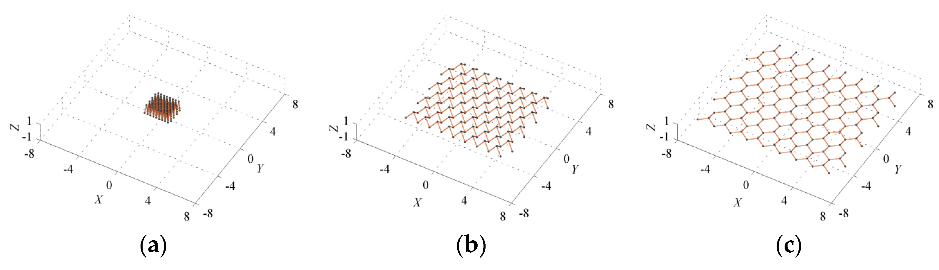
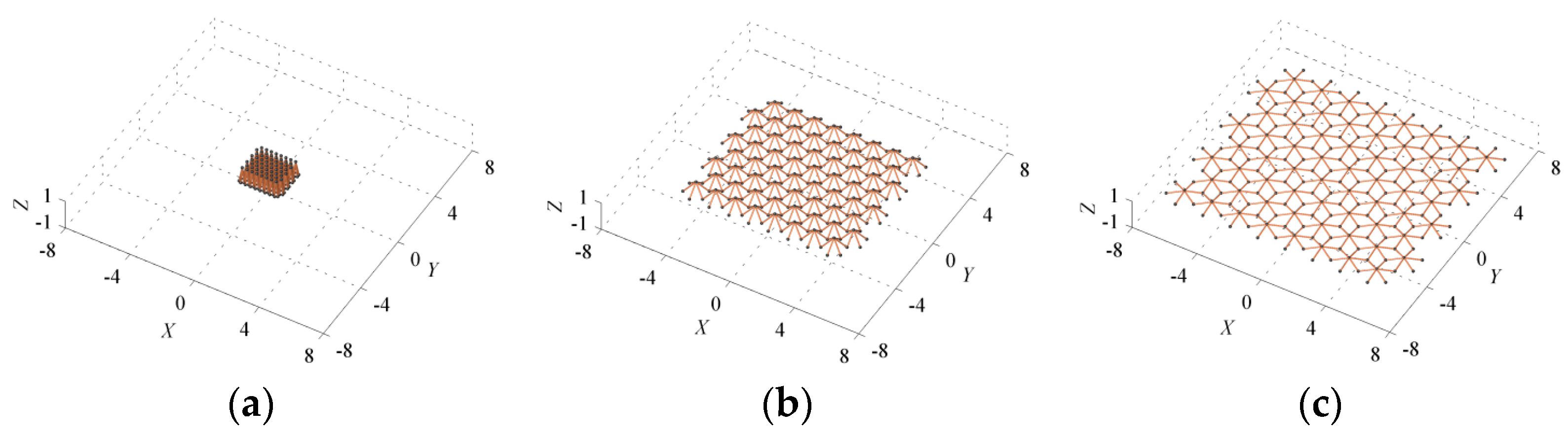
3.1. Feasible Deployable Structures with Different Types of Joints and Configurations

3.1.1. Case I: n1 = n2 = 4

To verify the feasibility of the obtained solutions, four links connected by a common joint is taken as a basic unit, whereas n1 = n2 = 4. Then, according to the periodic symmetry, a simple deployable structure with 2 × 2 basic units can be assembled by repeating and combining two basic units along both directions of a 2D space. This structure holds four-fold symmetry. Mobility analysis shows that this structure is deployable with one degree of freedom (m = 1). Typical configurations during deployment of the structure are shown in Figure 3. It verifies that the structure keeps its original symmetry during transformations.

3.1.2. Case II: n1 =2 and n2 = 4

Note that a joint will be connected to only two links when n1 = 2. Then, this type of joint is equivalent to the traditional revolute joint for deployable structures, where both of the two connected links rotate in the same plane.
For the case with n1 = 2 and n2 = 4, the basic unit consists of four straight links, an intersecting joint for connecting four links, and four joints for connecting two adjacent links. For example, Figure 4 shows a crystal-inspired deployable structure assembled by 6 × 6 basic units. It keeps four-fold symmetry, and shows smooth transformations along the motion path. With the mobility m = 1, this structure exhibits a satisfactory folding ratio. This can be observed from Figure 4 that the structure is compactly folded and then deployed into a much larger-scale structure.

3.1.3. Case III: n1 = n2 = 3

Another basic unit is formed by connecting three links to a common joint, on the condition that n1 = n2 = 3. This type of structures shows three-fold symmetry, where each joint is connected to three links. For example, a symmetric deployable structure is shown in Figure 5, which is assembled by 8 × 8 basic units. This structure exhibits strong regularity, and can be smoothly deployed from a compacted state. Kinematic analysis indicates that such a type of deployable structures has a single mode of finite mechanism (m = 1), and thus it is a feasible deployable structure.

3.1.4. Case IV: n1 = 3 and n2 = 6

For the fourth case with n1 = 3 and n2 = 6, the structural configuration is complex and composed of many more link members. The corresponding basic unit is formed by six links, which are intersected at the same joint, where the other end of each link is connected to two different links. For instance, Figure 6 shows typical configurations of a deployable structure with n1 = 3 and n2 = 6, which is also assembled by 8 × 8 basic units.
As expected, this structure exhibits three-fold symmetry and strong regularity. Notably, Figure 6 shows that this symmetric deployable structure can be smoothly transformed from the folded state to the fully deployed state, and the motion process is reversible. and can be smoothly deployed from a compacted state. During transformation, the joints attached on the two ends of a link member rotate on two different planes, where the rotation axes are parallel to each other. Moreover, because of the many more connected links, this type of structure shows much stronger stiffness than the structures presented above.

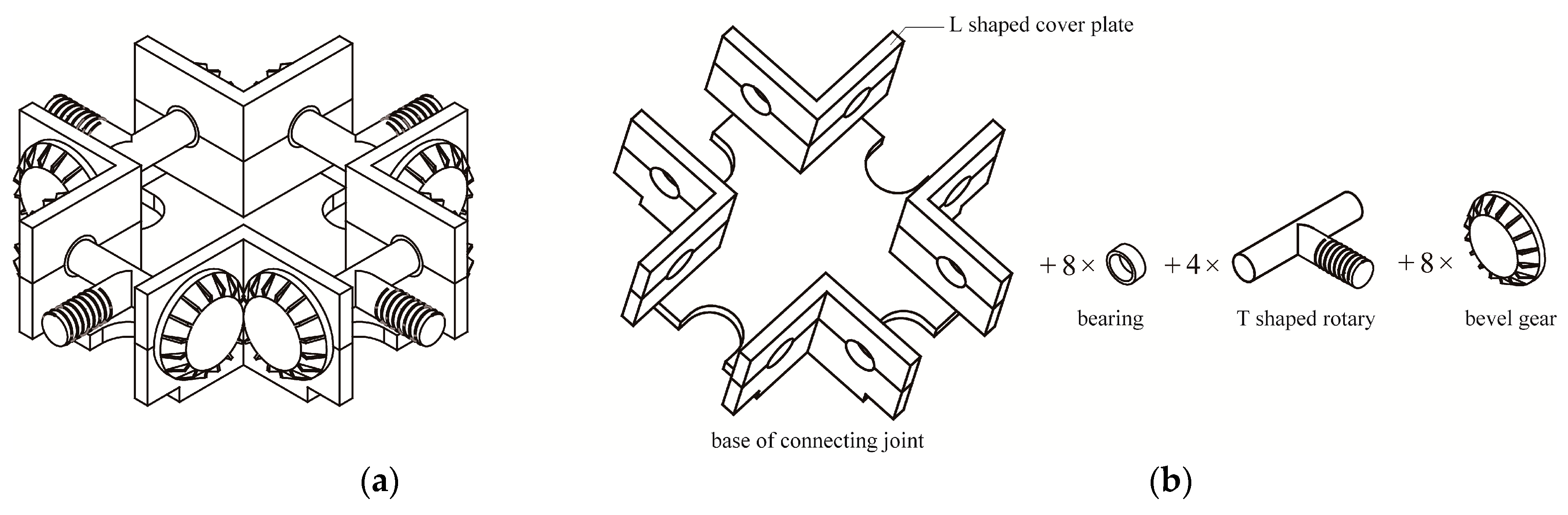
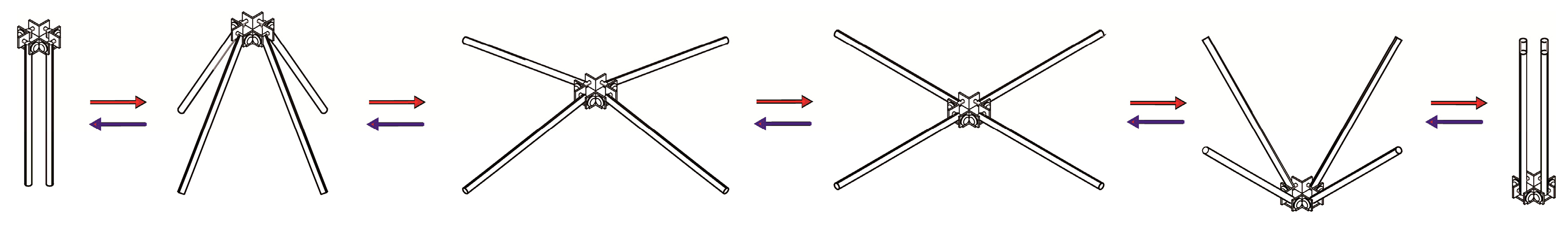
3.2. Avoiding Singularity by Novel Joints with Bevel Gears

It is important to note that these crystal-inspired deployable structures can be singular when the links intersected at the same joint become coplanar [2,18,26]. Thereafter, the compatibility matrix and the Jacobian matrix shown in Equation (5) become singular, and some additional mechanism modes are induced. Consequently, it is difficult to maintain synchronous motion of adjacent link members. Then, involved bifurcation paths lead these structures to get into singular configurations, which is known as the singularity of a deployable structure [18,27].
To avoid singularity of these deployable structures, a novel type of connecting joints with bevel gears is designed. Figure 7a illustrates an example of the joint with four pairs of bevel gears, which can ensure four connected links maintain synchronous motion. For clarity, Figure 6b describes the assembly of the joint.
As shown in Figure 7, this type of novel joint is generally assembled by the main base of the joint, n1 couples of L-shaped cover plates, n1 T-shaped rotary, and n1 pairs of bevel gears. The integer n 1 2 denotes the number of links connected to the joint. The n1 couples of L-shaped cover plates keep n-fold symmetry. Each T-shaped rotary is located between the two couples of L-shaped cover plates. In addition, each pair of the bevel gears meshes tightly, where the dihedral angle between the top surfaces of the gears is θ = 2 π / n 1 . In Figure 7, n 1 = 4 and θ = 0.5 π . Notably, to allow the connected links to be compactly folded, a total of n1 U-shaped notches are symmetrically set on the base of the connecting joint.
To verify the feasibility of the design of these novel joints, a specific joint connected by four links is assembled and evaluated, as shown in Figure 8. It turns out that the members maintain synchronous motion due to the intersecting joint with bevel gears, and the whole system keeps four-fold symmetry. The connected members are able to smoothly transform from one folded state to the other folded state. The whole process is reversible and repeatable, without singularity induced. These deployable structures are robust, and can obtain potential applications for retractable roof structures, medical devices, solar panels, and masts [1,28]. In addition, they can guide the construction and destruction process for engineering structures (e.g., cable domes and frame structures) [29,30].

4. Discussion

This study presents an innovative design of a variety of periodic deployable structures, inspired by the geometry of typical Bravais lattices in 2D space. It should be explained that there are many kinds of crystals (e.g., the known cubic ice and hexagonal ice crystals) [20,25], which include regular or nonregular geometry in 2D/3D space. On the condition that the complexity of joints or the regularity is weakened, certain types of joints and members with different lengths can be included in the unit cells of a deployable structure. Thereafter, many more crystal-inspired deployable structures can be proposed. However, a key point is that most of the joints should be under constraint and connected to a limited number of links [5,24] to guarantee the mobility of the proposed structures.
On the other hand, Section 3.2 briefly illustrates the concept design of novel joints with a number of pairs of bevel gears. Importantly, each joint is not limited to being connected by four or six links, as this can be adjusted for different joints. For example, by modifying the base of the joint (see Figure 9), the angle between the bevel gears, and the other assembly, the joint can be designed to respectively connect three and five link members. Through comprehensive comparisons among the above-mentioned configurations, the structure with n1 = 3 and n2 = 6 has a better structural stiffness and redundancy. However, the difficulty of fabricating its joints and folding its links slightly increases. From practicality and feasibility points of view, the structure with n1 = n2 = 4 is favorable, as it exhibits satisfactory folding performance and rigidity.
In comparison with conventional joints for deployable structures, the presented joints have certain advantages. Because of the bevel gears, the connected link members can maintain synchronous rotations along the rotation axes. Then, potential singularity induced by the coplanarity of the links can be prevented. In addition, the U-shaped notches are helpful for improving the folding ratio of the structures. However, when the motion process calls for high precision, the accuracy of the bevel gear should be deliberately improved for the synchronous motion.

5. Conclusions

This study demonstrated the design of novel revolute joints with bevel gears to realize singularity avoidance and better deployment performance for crystal-inspired deployable structures. We showed that a number of innovative deployable structures can be developed by considering regular and symmetry, and adopting the geometry of typical 2D crystals. Singularity occurs frequently along the motion process of a deployable structure, which leads to bifurcated configurations. To avoid singularity, some connecting joints with bevel gears were presented. The obtained results verified that the proposed joint design has a satisfactory singularity avoidance capability and deployment performance. These crystal-inspired deployable structures can potentially play a positive role in design and engineering applications for deployable structures.

Author Contributions

Conceptualization, Y.C. and J.F.; Methodology and Analysis, Y.C. and J.Y.; Writing—Review and Editing, Y.C. and J.Y.; Supervision, Y.C. and J.F. All the authors participated in detailed discussion, drafting the paper, and producing the final version.

Funding

This research was funded by the National Natural Science Foundation of China (Grant No. 51508089 and No. 51850410513), and the Fundamental Research Funds for the Central Universities.

Acknowledgments

The first author would like to acknowledge financial support from the Alexander von Humboldt Foundation for his visiting research at Max-Planck-Institut für Eisenforschung GmbH, Germany. The authors are grateful to the anonymous reviewers for their suggestions.

Conflicts of Interest

The authors declare no conflict of interest.

References

  1. Pellegrino, S. Deployable Structures; Springer: Berlin/Heidelberg, Germany, 2014. [Google Scholar]
  2. Ding, X.; Yang, Y.; Dai, J.S. Design and kinematic analysis of a novel prism deployable mechanism. Mech. Mach. Theory 2013, 63, 35–49. [Google Scholar] [CrossRef]
  3. Chen, Y.; Sareh, P.; Yan, J.; Fallah, A.S.; Feng, J. An integrated geometric-graph-theoretic approach to representing origami structures and their corresponding truss frameworks. J. Mech. Design-Trans. ASME 2019, 141, 091402. [Google Scholar] [CrossRef]
  4. Kovacs, F.; Tarnai, T.; Fowler, P.W.; Guest, S.D. A class of expandable polyhedral structures. Int. J. Solids Struct. 2004, 41, 1119–1137. [Google Scholar] [CrossRef]
  5. Dai, J.S.; Zoppi, M.; Kong, X. Advances in Reconfigurable Mechanisms and Robots I; Springer: Berlin/Heidelberg, Germany, 2012. [Google Scholar]
  6. Nagaraj, B.P.; Pandiyan, R.; Ghosal, A. Kinematics of pantograph masts. Mech. Mach. Theory 2009, 44, 822–834. [Google Scholar] [CrossRef] [Green Version]
  7. Kuribayashi, K.; Tsuchiya, K.; You, Z.; Tomus, D.; Umemoto, M.; Ito, T.; Sasaki, M. Self-deployable origami stent grafts as a biomedical application of Ni-rich TiNi shape memory alloy foil. Mat. Sci. Eng. A.-Struct. 2006, 419, 131–137. [Google Scholar] [CrossRef]
  8. Beatini, V.; Royer-Carfagni, G. Cable-stiffened foldable elastica for movable structures. Eng. Struct. 2013, 56, 126–136. [Google Scholar] [CrossRef] [Green Version]
  9. Zhao, J.; Wang, J.; Chu, F.; Feng, Z.; Dai, J.S. Structure synthesis and statics analysis of a foldable stair. Mech. Mach. Theory 2011, 46, 998–1015. [Google Scholar] [CrossRef]
  10. Patel, J.; Ananthasuresh, G.K. A kinematic theory for radially foldable planar linkages. Int. J. Solids Struct. 2007, 44, 6279–6298. [Google Scholar] [CrossRef] [Green Version]
  11. Kaveh, A.; Shojaee, S. Optimal design of scissor-link foldable structures using genetic algorithm. In Proceedings of the Fourth International Conference on Engineering Computational Technology, Lisbon, Portugal, 7–9 September 2004. [Google Scholar]
  12. Kumar, P.; Pellegrino, S. Computation of kinematic paths and bifurcation points. Int. J. Solids Struct. 2000, 37, 7003–7027. [Google Scholar] [CrossRef]
  13. Gan, W.W.; Pellegrino, S. Numerical approach to the kinematic analysis of deployable structures forming a closed loop. P. I. Mech. Eng. C-J. Mec. 2006, 220, 1045–1056. [Google Scholar] [CrossRef]
  14. Chen, Y.; Fan, L.; Feng, J. Kinematic of symmetric deployable scissor-hinge structures with integral mechanism mode. Comput. Struct. 2017, 191, 140–152. [Google Scholar] [CrossRef]
  15. Lee, M.K.; Park, K.W. Workspace and singularity analysis of a double parallel manipulator. IEEE/ASME Trans. Mech. 2000, 5, 367–375. [Google Scholar]
  16. Bandyopadhyay, S.; Ghosal, A. Analysis of configuration space singularities of closed-loop mechanisms and parallel manipulators. Mech. Mach. Theory 2004, 39, 519–544. [Google Scholar] [CrossRef]
  17. Wei, G.W.; Chen, Y.; Dai, J.S. Synthesis, mobility and multifurcation of deployable polyhedral mechanisms with radially reciprocating motion. J. Mech. Design-Trans. ASME 2014, 136, 091003. [Google Scholar] [CrossRef]
  18. Chen, Y.; Feng, J.; Sun, Q. Lower-order symmetric mechanism modes and bifurcation behavior of deployable bar structures with cyclic symmetry. Int. J. Solids Struct. 2018, 139–140, 1–14. [Google Scholar] [CrossRef]
  19. Sheldrick, G.M. Crystal structure refinement with SHELXL. Acta Crystallogr. Sect. C Struct. Chem. 2015, 71, 3–8. [Google Scholar]
  20. Levine, D.; Steinhardt, P.J. Quasicrystals: A new class of ordered structures. Phys. Rev. Lett. 1984, 53, 2477. [Google Scholar] [CrossRef]
  21. Hunt, K.H. Kinematic Geometry of Mechanisms; Cambridge University Press: Oxford, UK, 1990. [Google Scholar]
  22. Guest, S.D.; Fowler, P.W. A symmetry-extended mobility rule. Mech. Mach. Theory 2005, 40, 1002–1014. [Google Scholar] [CrossRef]
  23. Chen, Y.; Sareh, P.; Feng, J.; Sun, Q. A computational method for automated detection of engineering structures with cyclic symmetries. Comput. Struct. 2017, 191, 153–164. [Google Scholar] [CrossRef]
  24. Chen, Y.; Feng, J.; Liu, Y. A group-theoretic approach to the mobility and kinematic of symmetric over-constrained structures. Mech. Mach. Theory 2016, 105, 91–107. [Google Scholar] [CrossRef]
  25. Bishop, D.M. Group Theory and Chemistry; Clarendon Press: Oxford, UK, 1973. [Google Scholar]
  26. Chen, Y.; Feng, J.; Ren, Z. Numerical approach for detecting bifurcation points of the compatibility paths of symmetric deployable structures. Mech. Res. Commun. 2016, 71, 7–15. [Google Scholar] [CrossRef]
  27. Zhang, T.; Huang, H.; Guo, H.; Li, B. Singularity avoidance for a deployable mechanism using elastic joints. J. Mech. Design 2019, 141, 094501. [Google Scholar] [CrossRef]
  28. Chen, Y.; Feng, J. Mobility of symmetric deployable structures subjected to external loads. Mech. Mach. Theory 2015, 93, 98–111. [Google Scholar] [CrossRef]
  29. Naser, M.Z.; Kodur, V.K.R. Cognitive infrastructure—A modern concept for resilient performance under extreme events. Automat. Constr. 2018, 90, 253–264. [Google Scholar] [CrossRef]
  30. Chen, Y.; Feng, J. Generalized eigenvalue analysis of symmetric prestressed structures using group theory. J. Compt. Civil Eng. ASCE 2012, 26, 488–497. [Google Scholar] [CrossRef]
Figure 1. Unit cells of deployable structures assembled by different types of joints, which are designed to respectively connect to n1 and n2 links: (a) n1 = 2, and n2 = 4; (b) n1 = n2 = 4.
Crystals 09 00421 g001
Figure 2. Feasible solutions to the compatibility conditions of the members given by Equations (3) and (4): (a) Three-dimensional (3D) view; (b) typical solutions marked by the dots.
Crystals 09 00421 g002
Figure 3. Motion of a deployable structure assembled by 2 × 2 basic units, with n1 = n2 = 4: (a) Folded configuration; (b) partially deployed configuration; (c) deployed configuration.
Crystals 09 00421 g003
Figure 4. Motion of a deployable structure assembled by 6 × 6 basic units, with n1 = 2 and n2 = 4: (a) Folded configuration; (b) partially deployed configuration; (c) deployed configuration.
Crystals 09 00421 g004
Figure 5. Motion of a deployable structure assembled by 8 × 8 basic units, with n1 = n2 = 3: (a) Folded configuration; (b) partially deployed configuration; (c) deployed configuration.
Crystals 09 00421 g005
Figure 6. Motion of a deployable structure assembled by 8 × 8 basic units, with n1 = 3 and n2 = 6: (a) Folded configuration; (b) partially deployed configuration; (c) deployed configuration.
Crystals 09 00421 g006
Figure 7. Design of a joint with four pairs of bevel gears and connected to n1 = 4 link members: (a) Sketch of the joint model; (b) basic components, including base, cover plate, bearing, rotary, and bevel gears.
Crystals 09 00421 g007
Figure 8. Synchronous and symmetric motion of n1 = 4 links connected the novel joint with bevel gears.
Crystals 09 00421 g008
Figure 9. Plan view and 3D view of the base of novel joints with bevel gears: (a) Connected to three link members; (b) connected to five link members.
Crystals 09 00421 g009

