Fast Ferroelectric Liquid Crystal Based Optical Switch: Simulation and Experiments


Abstract
1. Introduction
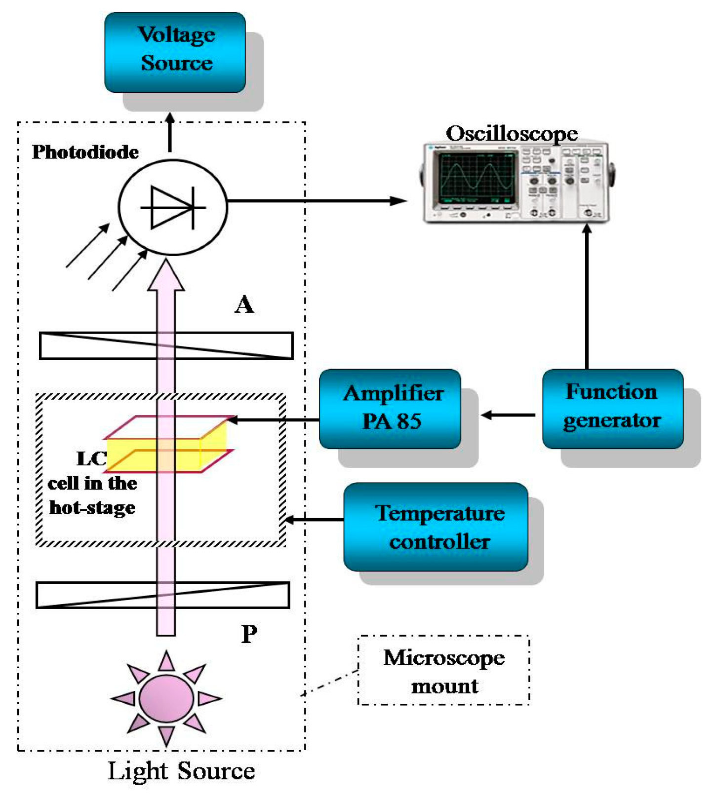
2. Experiments
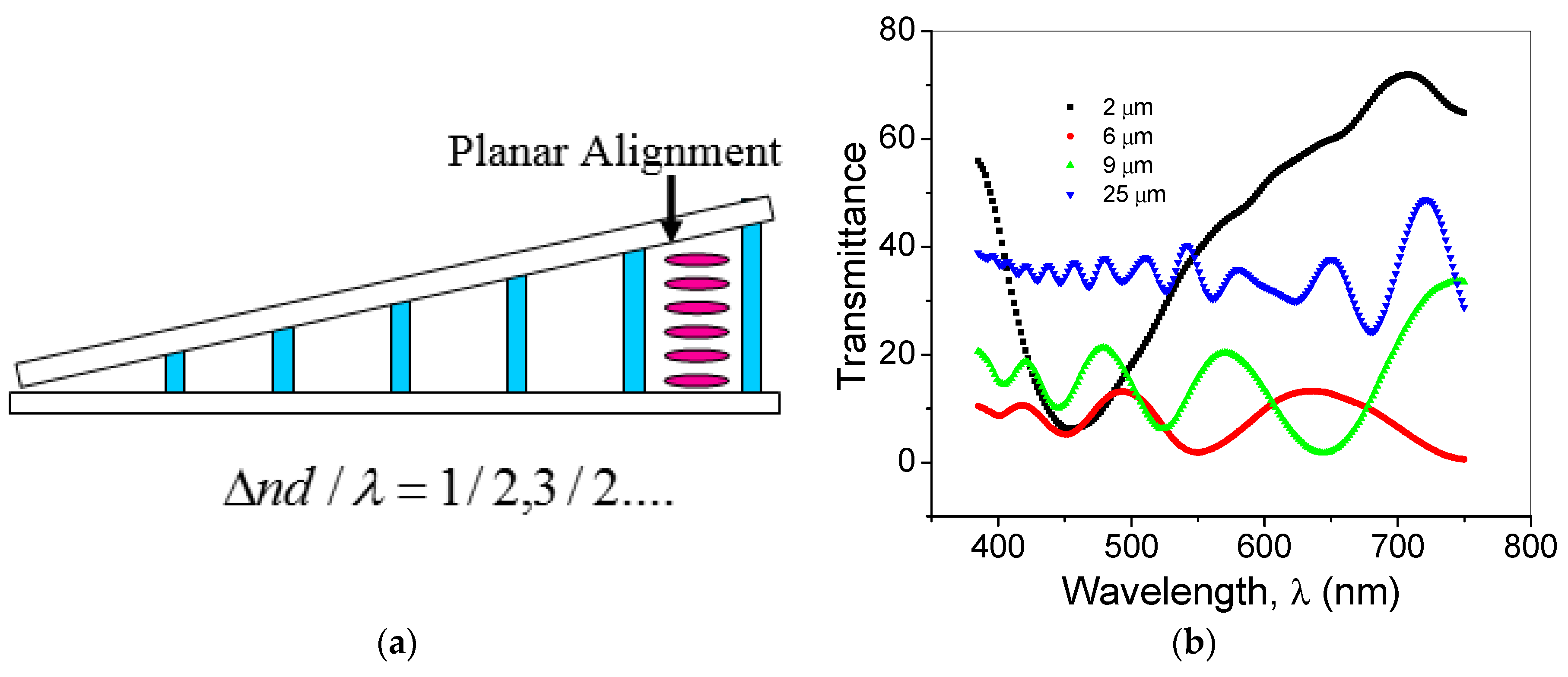
Cell Thickness Optimization
3. Optical Switching in FLC Modulator
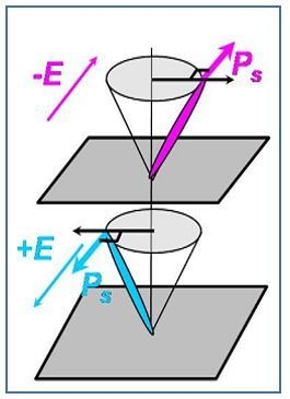
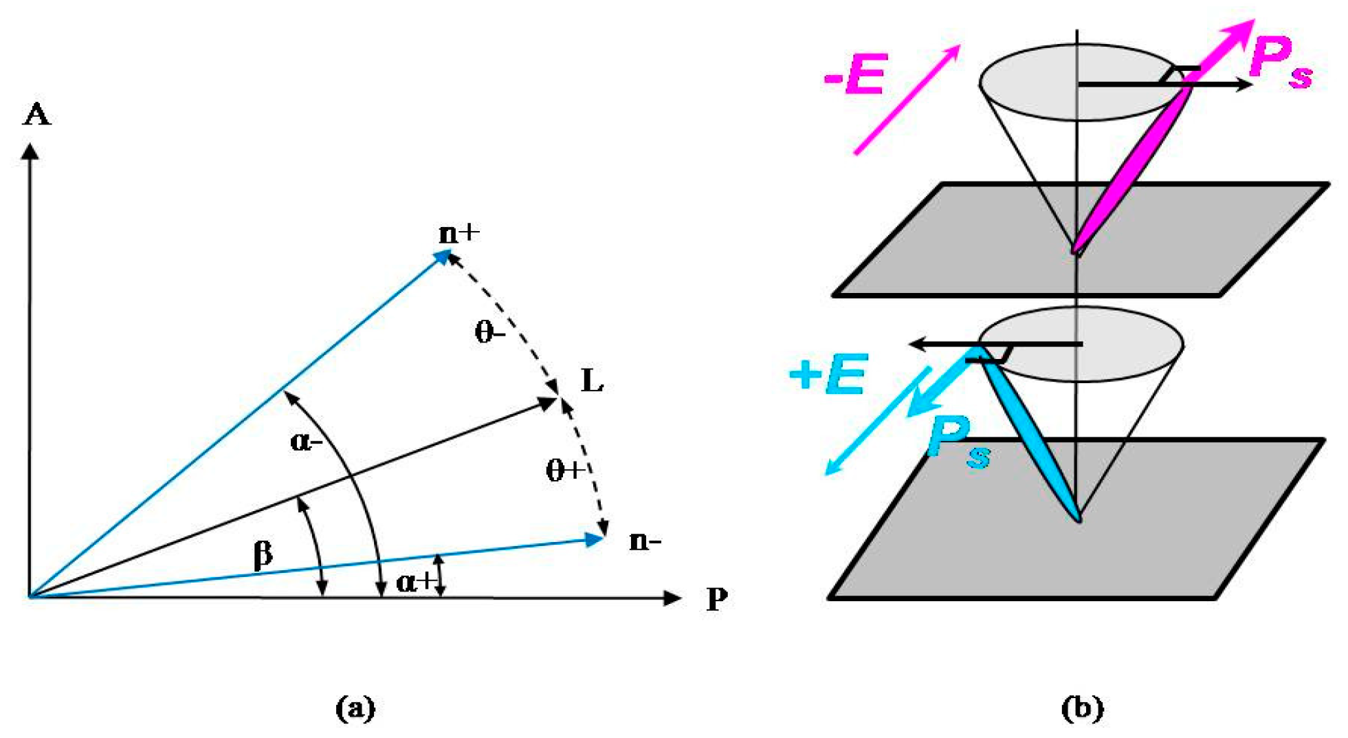
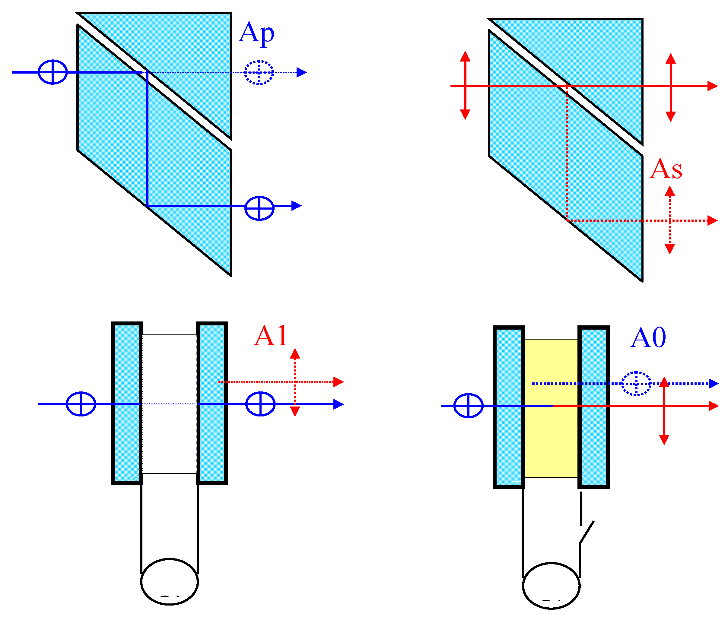
3.1. Principle of Operation
Binary Switch
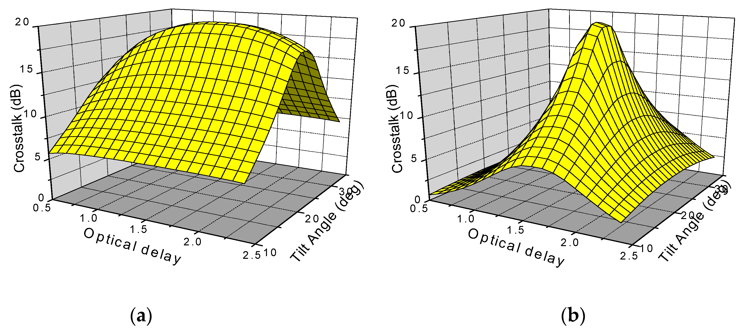
3.2. Simulation of Switch Performance Parameters
4. Results and Discussions
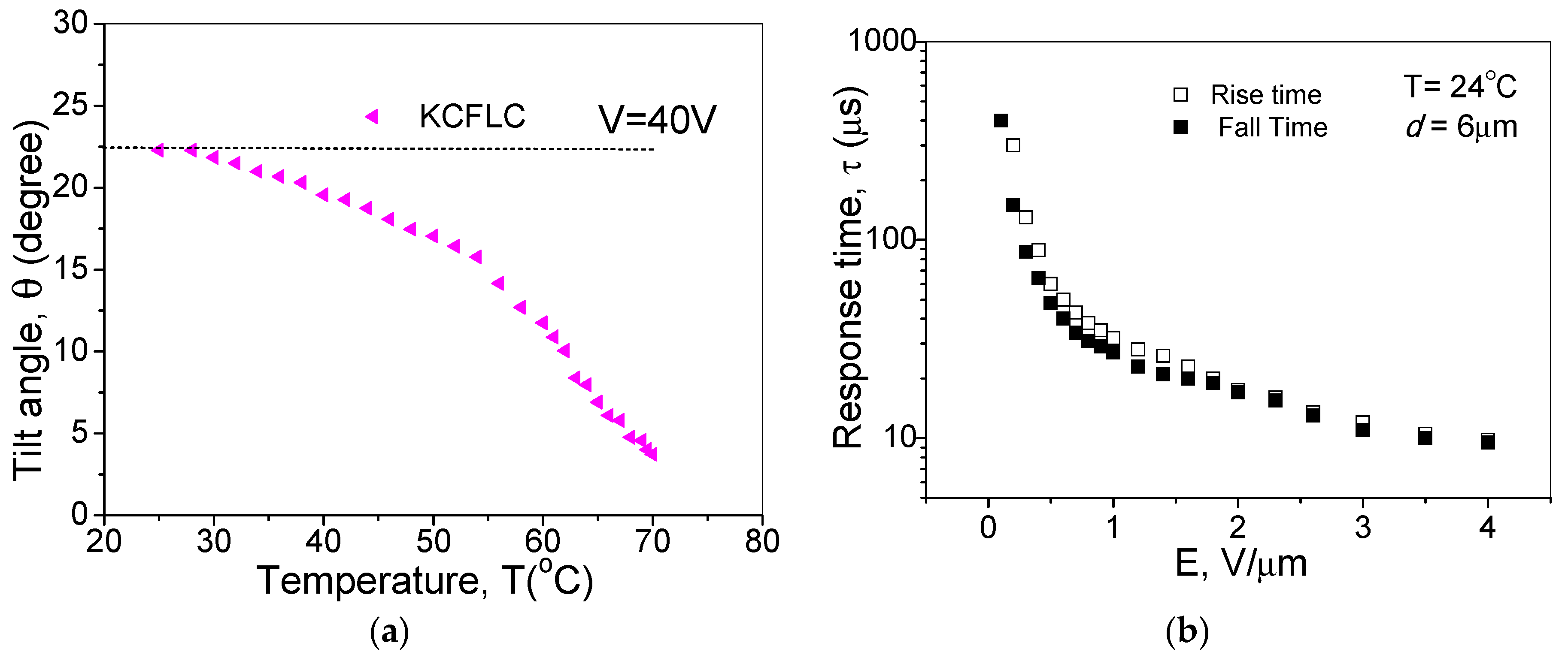
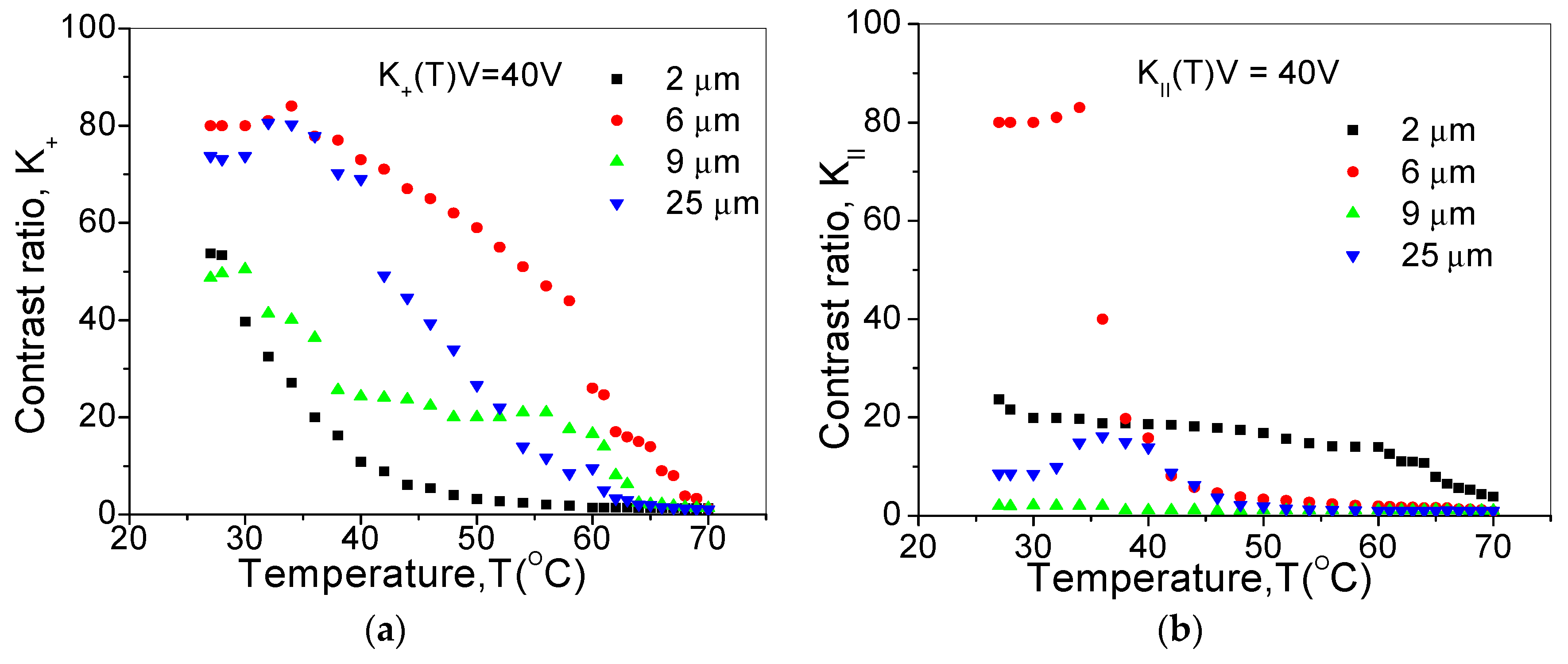
Electro-Optic Measurements
5. Conclusions
Author Contributions
Funding
Conflicts of Interest
References
- Fujiwara, M.; Goodman, M.; O’Mahony, M.; Tonguz, O.; Willner, A. Guest Editorial Multiwavelength Optical Technology and Networks. J. Light. Technol. 1996, 14, 932. [Google Scholar] [CrossRef]
- Cruz, R.L.; Hill, G.R.; Kellner, A.L.; Ramaswamy, R.; Sasaki, G.H.; Yamabayashi, Y. Guest Editorial Optical Networks. IEEE J. Select. Areas Commun. 1996, 14, 761. [Google Scholar] [CrossRef]
- Ollier, E. Optical MEMS devices based on moving waveguides. IEEE J. Sel. Top. Quantum Electron. 2002, 8, 155. [Google Scholar] [CrossRef]
- Wang, X.; Howley, B.; Chen, M.; Chen, R. 4×4 Nonblocking Polymeric Thermo-Optic Switch Matrix Using the Total Internal Reflection Effect. IEEE J. Sel. Top. Quantum Electron. 2006, 12, 997. [Google Scholar] [CrossRef]
- Ho, K.P.; Liaw, S.K. Demultiplexer Crosstalk Rejection Requirements for Hybrid WDM System with Analog and Digital Channels. IEEE Photon. Technol. Lett. 1998, 10, 737. [Google Scholar] [CrossRef]
- Wang, H.; Li, X.; Zhang, M.; Chen, K. Broadband 2×2 lithium niobate electro-optic switch based on a Mach–Zehnder interferometer with counter-tapered directional couplers. Appl. Opt. 2017, 56, 8164. [Google Scholar] [CrossRef]
- Stephens, M.F.C.; Asghari, M.; Penty, R.V.; White, I.H. Demonstration of ultrafast all-optical wavelength conversion utilizing birefringence in semiconductor optical amplifiers. IEEE Photon. Technol. Lett. 1997, 9, 449. [Google Scholar] [CrossRef]
- Banchi, L.; Presi, M.; D’Errico, A.; Contestabile, G.; Ciaramella, E. All-optical 10 and 40 Gbit/s RZ-to-NRZ format and wavelength conversion using semiconductor optical amplifiers. J. Lightwave Technol. 2010, 28, 32. [Google Scholar] [CrossRef]
- Nolting, H.P.; Gravert, M.; Bachmann, M.; Renaud, M. Crosstalk Reduced Digital Optical Switch with Single Electrode Designed for InP. Opt. Amplif. Appl. 1996, 6, 637. [Google Scholar]
- Shigeto, K.; Seiiti, S.; Yoshie, T.; Noriyoshi, Y. Ferroelectric liquid crystal driving method for optical switching devices in communication networks. Ferroelectrics 1993, 149, 159. [Google Scholar]
- Panarin, Y.; Sreenilayam, S. FLC based matrix optical switch. In Proceedings of the International Conference on Photonics in Switching, Pisa, Italy, 15–19 September 2009. [Google Scholar]
- Schadt, M.; Seiberle, H.; Schuster, A. Optical patterning of multi-domain liquid-crystal displays with wide viewing angles. Nature 1996, 381, 212. [Google Scholar] [CrossRef]
- Saito, I.; Ono, H.; Kawatsuki, N. Photorefractive Bragg diffraction in high- and low-molar-mass liquid crystal mixtures. Appl. Phys. Lett. 1998, 72, 1942. [Google Scholar]
- Sreenilayam, S.P.; Panarin, Y.P.; Vij, J.K.; Lehmann, A.; Poppe, M.; Tschierske, C. Development of ferroelectricity in the smectic phases of 4-cyanoresorcinol derived achiral bent-core liquid crystals with long terminal alkyl chains. Phys. Rev. Mater. 2017, 1, 035604. [Google Scholar] [CrossRef]
- Sreenilayam, S.P.; Panarin, Y.P.; Vij, J.K.; Panov, V.P.; Lehmann, A.; Poppe, M.; Prehm, M.; Tschierske, C. Spontaneous helix formation in non-chiral bent-core liquid crystals with fast linear electro-optic effect. Nat. Commun. 2016, 7, 11369. [Google Scholar] [CrossRef]
- Panarin, Y.P.; Sreenilayam, S.P.; Vij, J.K.; Lehmann, A.; Tschierske, C. A fast linear electro-optical effect in a non-chiral bent-core liquid crystal. J. Mater. Chem. C 2017, 5, 12585. [Google Scholar] [CrossRef]
- Vij, J.K.; Panarin, Y.P.; Sreenilayam, S.P.; Alaasar, M.; Tschierske, C. Investigation of the heliconical smectic SmCSPFhel phase in achiral bent-core mesogens derived from 4-cyanoresorcinol. Phys. Rev. Mater. 2019, 3, 045603. [Google Scholar] [CrossRef]
- Srivastava, A.; Hu, W.; Chigrinov, V.; Kiselev, A.; Lu, Y.Q. Fast switchable grating based on orthogonal photo alignments of ferroelectric liquid crystals. Appl. Phys. Lett. 2012, 101, 031112. [Google Scholar] [CrossRef]
- Chigrinov, V.; Manohar, R.; Srivastava, A.; Pozhidaev, E.P. Single walled carbon nano-tube, ferroelectric liquid crystal composites: Excellent diffractive tool. Appl. Phys. Lett. 2011, 99, 201106. [Google Scholar]
- Sreenilayam, S.P.; Agra-Kooijman, D.M.; Panov, V.P.; Swaminathan, V.; Vij, J.K.; Panarin, Y.P.; Kocot, A.; Panov, A.; Rodriguez-Lojo, D.; Stevenson, P.J. Phase behavior and characterization of heptamethyltrisiloxane-based de Vries smectic liquid crystal by electro-optics, x rays, and dielectric spectroscopy. Phys. Rev. E 2017, 95, 032701. [Google Scholar] [CrossRef]
- Larsen, T.T.; Bjarklev, A.; Sparre, D.H.; Broeng, J. Optical devices based on liquid crystal photonic bandgap fibres. Optics Express 2003, 11, 2589. [Google Scholar] [CrossRef]
- Soref, R.A.; McMahon, D.H. Calcite 2×2 optical bypass switch controlled by liquid-crystal cells. Opt. Lett. 1982, 7, 186. [Google Scholar] [CrossRef]
- Fuji, Y. Low-Crosstalk 1×2 Optical Switch Composed of Twisted Nematic Liquid Crystal Cells. IEEE. Photon. Lett. 1993, 5, 206. [Google Scholar] [CrossRef]
- Pozhidaev, E.P.; Chigrinov, V.G.; Du, T. Fast Switching Bistable Ferroelectric Liquid Crystal Switches as a New Optical Elements for Photonics Applications. In Proceedings of the 14th OptoElectronics and Communications Conference, Vienna, Austria, 13–17 July 2009. [Google Scholar] [CrossRef]
- Chigrinov, V.G. Liquid Crystal Applications in Photonics. In Proceedings of the Photonics West Conference, San Jose, CA, USA, 25–28 January 2009. [Google Scholar]
- Soref, R.A. Low-cross-talk 2×2 optical switch. Opt. Lett. 1981, 6, 275. [Google Scholar] [CrossRef]
- Shankar, N.; Morris, J.; Yakymyshyn, C.; Pollock, C. A 2×2 fiber optic switch using chiral liquid crystals. IEEE Photon. Technol. Lett. 1990, 2, 147. [Google Scholar] [CrossRef]
- Meyer, R.; Liebert, L.; Strzelecki, L.; Keller, P. Ferroelectric liquid crystals. J. Phys. Lett. 1975, 36, 69. [Google Scholar] [CrossRef]
- Riza, N.; Yuan, S. Low optical interchannel crosstalk, fast switching speed, polarisation independent 2×2 fibre optic switch using ferroelectric liquid crystals. Electron. Lett. 1998, 34, 1341. [Google Scholar] [CrossRef]
- Sreenilayam, S.P.; Panov, V.P.; Vij, J.K.; Shanker, G. The NTB phase in an achiral asymmetrical bent-core liquid crystal terminated with symmetric alkyl chains. Liq. Cryst. 2017, 44, 244. [Google Scholar] [CrossRef]
- Sreenilayam, S.P.; Panarin, Y.P.; Vij, J.K.; Torgova, S.I.; Lehmann, A.; Tschierske, C. Flexoelectric polarization studies in bent-core nematic liquid crystals. Phys. Rev. E 2015, 92, 022502. [Google Scholar] [CrossRef]
- Torgova, S.; Sreenilayam, S.P.; Panarin, Y.P.; Francescangeli, O.; Vita, F.; Vij, J.K.; Pozhidaev, E.; Minchenko, M.; Ferrero, C.; Strigazzi, A. Short bent-core molecules: X-ray, polarization, dielectricity, texture and electro-optics investigations. Phys. Chem. Chem. Phys. 2017, 19, 22946. [Google Scholar] [CrossRef]
- Sreenilayam, S.P.; Rodriguez-Lojo, D.; Panov, V.P.; Swaminathan, V.; Vij, J.K.; Panarin, Y.P.; Gorecka, E.; Panov, A.; Stevenson, P.J. Design and investigation of de Vries liquid crystals based on 5-phenyl-pyrimidine and( R, R )2,3-epoxyhexoxy backbone. Phys. Rev. E 2017, 96, 042701. [Google Scholar] [CrossRef]
- Swaminathan, V.; Panov, V.P.; Panarin, Y.P.; Sreenilayam, S.P.; Vij, J.K.; Panov, A.; Rodriguez-Lojo, D.; Stevenson, P.J.; Gorecka, E. The effect of chiral doping in achiral smectic liquid crystals on the de Vries characteristics: Smectic layer thickness, electro-optics and birefringence. Liq. Cryst. 2018, 45, 513. [Google Scholar] [CrossRef]
- Sreenilayam, S.P.; Panarin, Y.P.; Vij, J.K.; Lehmann, A.; Tschierske, C. Physical Properties of SmAb Phase in an Achiral Bent–Core Smectic Liquid Crystal. Ferroelectrics 2012, 431, 196. [Google Scholar] [CrossRef]
- Sreenilayam, S.P.; Rodriguez-Lojo, D.; Agra-Kooijman, D.M.; Vij, J.K.; Panov, V.P.; Panov, A.; Fisch, M.R.; Kumar, S.; Stevenson, P.J. de Vries liquid crystals based on a chiral 5-phenylpyrimidine benzoate core with a tri- and tetra-carbosilane backbone. Phys. Rev. Mater. 2018, 2, 025603. [Google Scholar] [CrossRef]
- Alex, V.; Dubtsov, A.; Panarin, Y.; Wilkinson, T. Optical Performance of Non-blocking 4×4 Optical Switch: Simulation and Experiment. Euro. Disp. 2007, S9-3, 161. [Google Scholar]
- Fracasso, B.; de Bougrenet de la Tocnaye, J.L.; Noirie, L.; Razzak, M.; Danniel, E. Performance Assessment of a Liquid Crystal Multichannel Photonic Spaceswitch. In Photonics in Switching (Technical Digest); Academic Press: Cambridge, MA, USA, 2001; p. 24. [Google Scholar]
- Yuliya, S.; Gerald, F.; Qian, W. Fast free-space photonic switch based on a ferroelectric liquid crystal. Proc. SPIE 2006, 6185, 618518. [Google Scholar]


| Cross-Talk Sources | Measured Cross-Talk in (dB) |
|---|---|
| Ap | 27 |
| As | 19 |
| A1(A+) | 21 |
| A0(A||) | 19 |
© 2019 by the authors. Licensee MDPI, Basel, Switzerland. This article is an open access article distributed under the terms and conditions of the Creative Commons Attribution (CC BY) license (http://creativecommons.org/licenses/by/4.0/).
Share and Cite
Sreenilayam, S.P.; Brabazon, D.; Panarin, Y.P. Fast Ferroelectric Liquid Crystal Based Optical Switch: Simulation and Experiments. Crystals 2019, 9, 388. https://doi.org/10.3390/cryst9080388
Sreenilayam SP, Brabazon D, Panarin YP. Fast Ferroelectric Liquid Crystal Based Optical Switch: Simulation and Experiments. Crystals. 2019; 9(8):388. https://doi.org/10.3390/cryst9080388
Chicago/Turabian StyleSreenilayam, Sithara P., Dermot Brabazon, and Yuri P. Panarin. 2019. "Fast Ferroelectric Liquid Crystal Based Optical Switch: Simulation and Experiments" Crystals 9, no. 8: 388. https://doi.org/10.3390/cryst9080388
APA StyleSreenilayam, S. P., Brabazon, D., & Panarin, Y. P. (2019). Fast Ferroelectric Liquid Crystal Based Optical Switch: Simulation and Experiments. Crystals, 9(8), 388. https://doi.org/10.3390/cryst9080388