Article

Photonic Topological States in a Two-Dimensional Gyrotropic Photonic Crystal

1
National Laboratory of Solid State Microstructures, College of Engineering and Applied Sciences & Department of Materials Science and Engineering, Nanjing University, Nanjing 210093, China
2
International Center for Materials Nanoarchitectonics (WPI-MANA), National Institute for Materials Science (NIMS), Tsukuba 305-0044, Japan
3
Collaborative Innovation Center of Advanced Microstructures, Nanjing University, Nanjing 210093, China
*
Authors to whom correspondence should be addressed.
Crystals 2019, 9(3), 137; https://doi.org/10.3390/cryst9030137
Submission received: 6 February 2019 / Revised: 1 March 2019 / Accepted: 2 March 2019 / Published: 7 March 2019
(This article belongs to the Special Issue Recent Advances in Novel Topological Materials)

Abstract

:
Time-reversal symmetry (TRS) of electrons is associated with an anti-unitary operator with T 2 = 1 , which induces Kramers degeneracy and plays an important role in realizing the quantum spin Hall effect (QSHE). By contrast, TRS of photons is described by T b 2 = 1 . We point out that due to this difference, TRS is not the necessary condition for the construction of the photonic analogue of the QSHE. Instead, by constructing an artificial pseudo TRS T p with T p 2 = 1 in a photonic system, one can realize the photonic Kramers degeneracy and a pair of topological protected edge states, a photonic analogue of the QSHE. Specifically, by retrieving the optical parameters of materials with the pseudo TRS, we propose a photonic topological insulator (PTI) utilizing a pair of double-degenerate transverse electric (TE) and transverse magnetic (TM) polarizations to mimic the spin up and down states of the electron. We demonstrate that the unidirectional polarization-dependent transportation of TE and TM edge states can be realized in this system based on computer simulations. For all possible symmetry types, we check the robustness of these topological states by using a complete set of impurities, including three Pauli matrices and one complex conjugate operator. The results show that the PTI is protected by the pseudo TRS T p . In general, an arbitrary pair of optical polarizations on the Bloch sphere can be utilized to construct photonic pseudospin states and the PTI. Our findings confirm the physical meaning of the pseudo TRS and may provide guidance for future PTI designs.

1. Introduction

In condensed matter physics, symmetry-related topological properties are global properties of the energy band which always indicate the emergence of novel phases and play an important role in various physical systems [1,2,3,4,5,6,7,8,9,10,11]. For example, in systems with broken time-reversal symmetry (TRS), a non-zero Chern number leads to the quantum Hall effect [1,2,3,4]. In systems with unbroken TRS, Z 2 invariant characterizes the quantum spin Hall effect (QSHE), i.e., the topological insulator (TI), which exhibits edge spin transportations protected by TRS [5,6,7,8,9,10,11]. Since both solid-states physics and artificial crystal structures obey the similar band theory, a number of creative works with topological properties have been proposed in the realm of bosonic systems, including photonic crystals [12,13,14,15,16,17,18,19,20,21,22,23,24,25]. The photonic integer quantum Hall effect has been realized using two-dimensional gyroelectric or gyromagnetic photonic crystals in the presence of an external magnetic field [12,13,14,15]. The photonic Floquet topological insulator has been successfully demonstrated by breaking z-axis spatial-inversion symmetry with helical waveguides as well [16,17,18]. Using periodical arrays of coupled resonator optical waveguides with unbroken TRS, photonic anomalous Floquet topological insulators can also be realized for two uncoupled clockwise and anti-clockwise circulating modes in the two-dimensional case [19,20]. However, demonstrating a photonic analogue of the QSHE, i.e., a photonic topological insulator (PTI), is not straightforward. The degrees of freedom of photons need to be increased to double degeneracy which will experience opposite gauge fields with pseudospin-orbit coupling. Therefore, doubly degenerated transverse electric (TE) + transverse magnetic (TM)/TE − TM photonic hybrid polarizations in bi-anisotropic materials or p + d/pd orbital-like TM modes near double Dirac cones due to the band folding mechanism are proposed to construct PTIs with TRS [18,21,22,23,24,25].
Recently, He et al. [26] has proposed a PTI based on two circular polarized modes under a broken TRS condition. They showed that the robustness of the polarization-dependent transportation in PTI is not protected by bosonic TRS T b ( T b 2 = 1 ) but by an artificial pseudo TRS T p = i σ y K ( σ y is the y-component Pauli matrix, K is the complex conjugate and T p 2 = 1 ) [26]. This indicates that the bosonic TRS T b is not the necessary condition in realizing a PTI. Following this principle to only consider T p , we can have more choices of photonic pseudo-spins and material types to design a desirable PTI. Taking a polarization-based PTI as an example, if the system is set to have both TRS and pseudo TRS, there only exists one definite solution that is TE + TM/TE − TM for PTIs, no matter how the degeneracy is created [18,21,22,27]. On the contrary, without considering bosonic TRS, there will be more choices on the Bloch sphere to construct a PTI.
In this work, based on the pseudo TRS T p , we propose an alternative PTI model utilizing TE and TM polarizations as a basis, which is another pair of polarization-based PTIs on the Bloch sphere. By substituting such a pair into the Hamiltonian of PTI and Maxwell equations, we retrieve suitable types of materials which possessing both gyroelectric and gyromagnetic properties. In this PTI, there are a pair of gapless boundary states represented by the TE and TM modes, respectively, which propagate in opposite directions along the boundary leading to zero net energy flow. Furthermore, we test the robustness of our PTI using a complete set of impurities according to the Pauli matrices and complex conjugate operator, proving the T p protected property. A method based on the tight-binding approximation is used to analyze the edge states, which confirms the numerical results. The topological index, namely the spin Chern number C T M / T E = ± 1 , is also calculated to verify the non-trivial topological property of the photonic crystal energy band.

2. Method

Numerical investigations in this work were conducted using a hybrid RF mode of commercial FEM software (COMSOL Multiphysics, COMSOL Inc., Stockholm, Sweden, Version 5.1). The parameters used in numerical investigations were based on an yttrium-iron-garnet crystal at 4.28 GHz.

3. Results

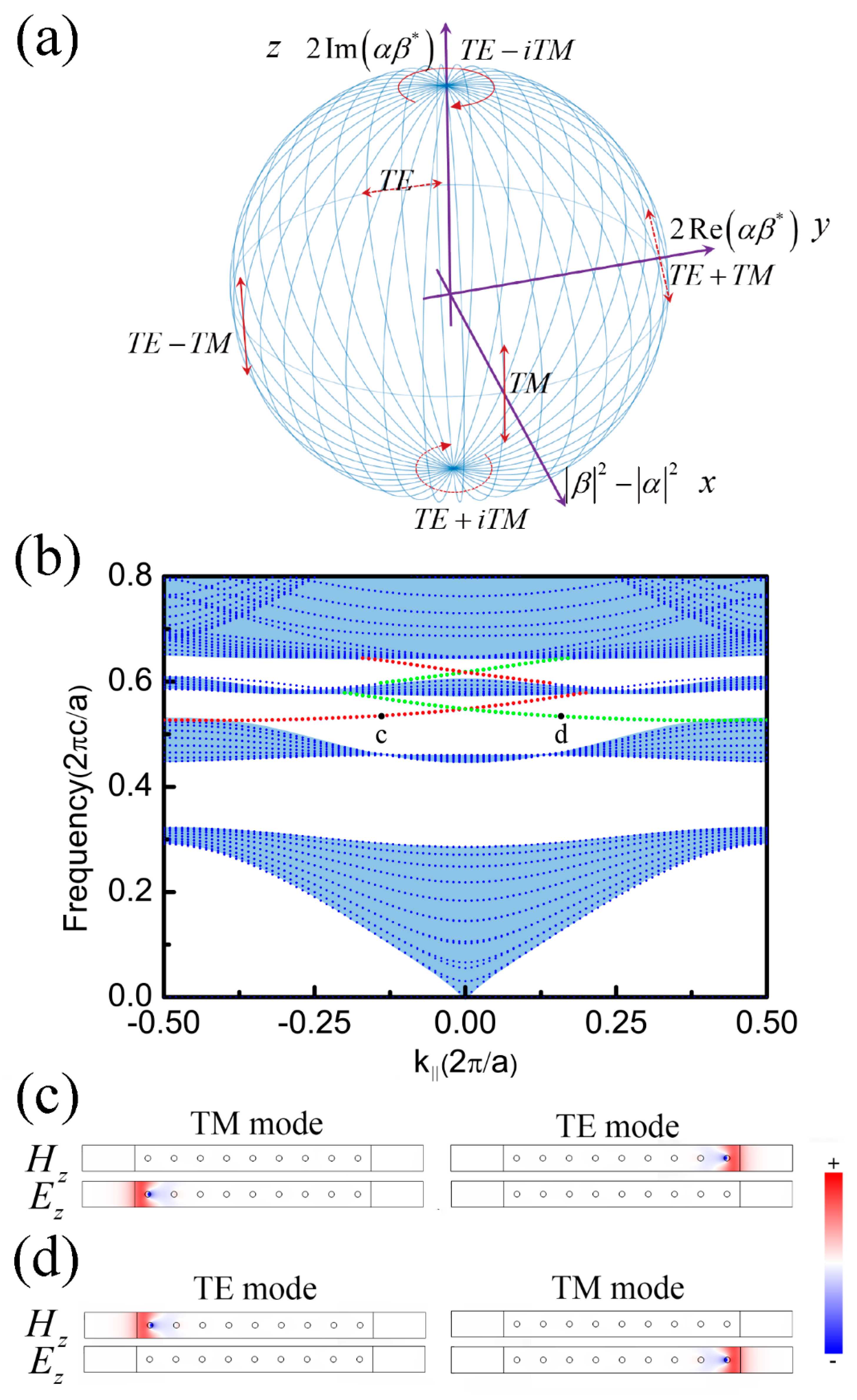
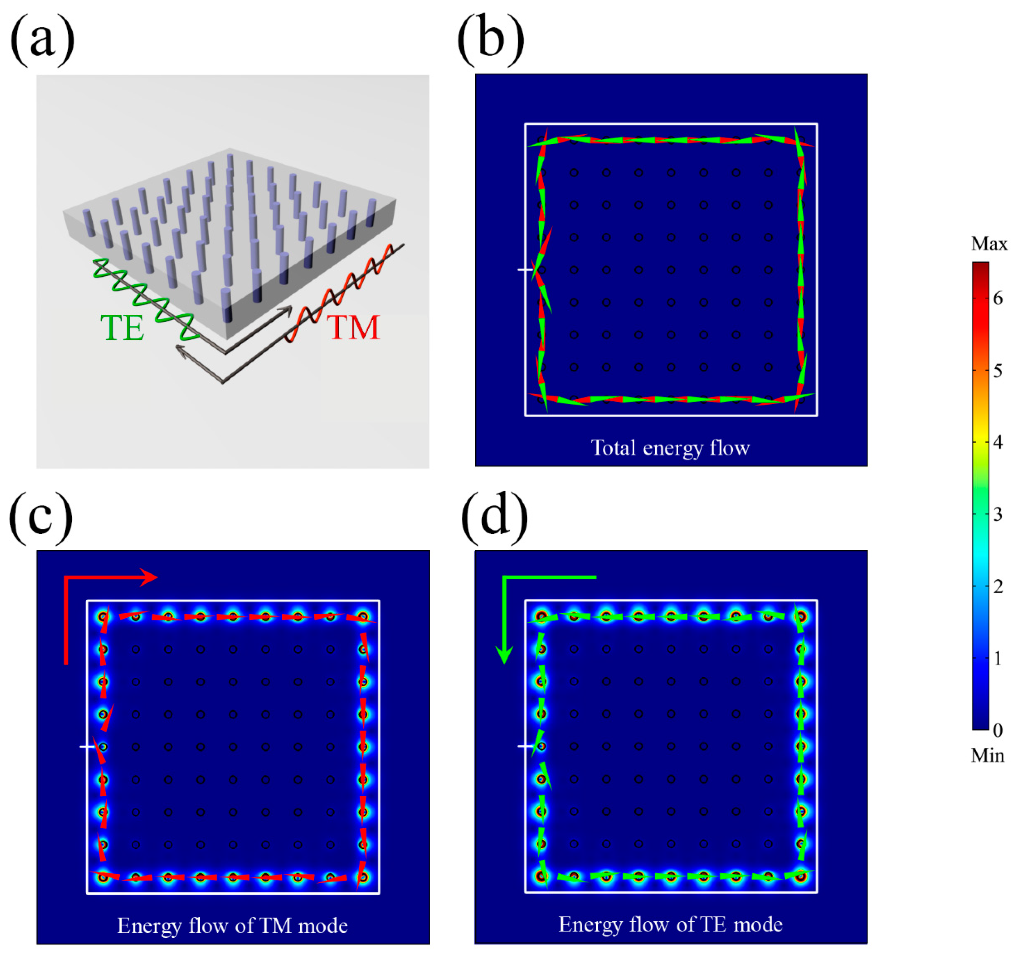
3.1. PTI Model and Gapless Edge States

Figure 1a shows the Bloch sphere description of the optic polarizations, where three bases are represented by a two-component vector ( α , β ) T , e.g., T E = ( 1 , 0 ) T ,   T M = ( 0 , 1 ) T . By setting | β | 2 | α | 2 , 2 Re ( α β ) , and 2 Im ( α β ) as the three orthogonal axes x, y, and z, the three paired bases on the x, y, and z directions are TE/TM, TE + TM/TE − TM, and TE + iTM/TE − iTM, respectively. One of these should be chosen to be the pseudospins for a PTI system. Then, the Hamiltonian of the system can be written as a 2 by 2 diagonal matrix when the pseudospin states are taken as the basis, which is a linear combination of I , i I , σ z , and i σ z . Because T p symmetry ( T p = i σ y K ) [26] is the necessary condition for constructing a polarization-based PTI, the Hamiltonian is further limited as a combination of I and i σ z with [ T p , I ] = 0 and [ T p , i σ z ] = 0 . If we also require the system to satisfy TRS ( T b symmetry), it is easy to find that only the two pole points of the Bloch sphere, TE + TM/TE − TM polarization, can be the candidate. The reason is that with basis TE + TM/TE − TM polarization, the TRS operator can be written as T b = σ x K , which satisfies [ T b , I ] = 0 and [ T b , i σ z ] = 0 . Thus, the PTI can be realized by using effective bi-anisotropic materials [18]. However, without the restriction of the TRS, TE + iTM/TE − iTM (left/right circularly) polarized waves can also be used to realize the PTI using Tellegen material [26,28]. As we can see, there still remains a basis of polarizations TE/TM on the Bloch sphere to construct the PTI. In this work, we choose TE/TM polarizations to replenish the integrity of the polarization-based PTI, which indicates that not only three pairs of poles but also any pair of polarizations on the Bloch sphere can be selected to construct the PTI.
As revealed above, the Hamiltonian should be a combination of I and i σ z , and hence we write down the Hamiltonian explicitly as
H ^ [ E z H z ] = [ 0 i 1 0 0 0 + i 1 ] [ E z H z ] = 0
with 0 = k 0 2 ε + x γ x + y γ y and 1 = x κ y y κ x , where k 0 , γ , κ , and ε are optical parameters which need to be retrieved in the following steps. It should be noticed that we have used E z and H z components to represent the TM and TE modes. In Equation (1), the real part 0 represents the transport of energy flow and the imaginary part 1 indicates the pseudospin coupling effect. It is obvious that [ H ^ , T p ] = 0 with T p = i σ y K , which means the system can be used to construct Kramers degeneracy and the PTI. Combing Equation (1) with the general constitutive relation of materials
[ D B ] = [ ε ξ ζ μ ] [ E H ]
we can obtain one possible kind of gyro-material: ε d = μ d , ε f = μ f , and ε = μ , where the relative permittivity and permeability tensors of the implemented gyrotropic material in our photonic crystal can be described as:
ε = [ ε d i ε f 0 i ε f ε d 0 0 0 ε ] , μ = [ μ d i μ f 0 i μ f μ d 0 0 0 μ ] , ξ = ζ = 0
Thus, we can derive γ = μ d / ( μ d 2 μ f 2 ) and κ = μ f / ( μ d 2 μ f 2 ) in Equation (1) in lossless condition [29].
Based on such a material model, we propose an yttrium-iron-garnet crystal-based photonic crystal which consists of periodic gyrotropic cylinders (in which radius r = 0.11 a and a is the lattice constant) under an external magnetic field at microwave frequencies. The corresponding parameters are μ d = 14 , μ f = 12.4 , and ε = 15 [30]. To satisfy the aforementioned requirement, the other parameters are assumed to be ε d = 14 , ε f = 12.4 , and μ = 15 .
Figure 1b shows the projected band structures of the proposed PTI, in which the blue dotted lines represent the degenerate bulk states (shadow region) while the green and red dotted lines between the second and the third energy bands represent the two edge states for the TE and TM modes. Figure 1c,d are the field distribution of point c and d marked in Figure 1b, respectively. The edge states are analyzed and confirmed in a three-layer sandwiched waveguide configuration. Its cladding/boundary layer has parameters ε = d i a g { 1 , 1 , 1 } and μ = d i a g { 1 , 1 , 1 } , which satisfies pseudo TRS and confines the light traveling along the waveguide-cladding interface [15,31,32]. At the frequency corresponding to point c, localized electric (magnetic) field distribution at the left (right) interface suggests that the left (right) interface only supports the TM (TE) mode. The dispersion curve’s slope is always positive in this case, indicating the light travels in a forward direction. On the other hand, the properties at point d are completely reversed. Therefore, only clockwise (anti-clockwise) scattering for the TM (TE) wave is allowed to travel along the boundary. The one-way propagating condition is the opposite for the edge states in the third gap. It is worth noting that other types of boundaries can also be used, such as a photonic crystal-air interface [32,33].
Figure 2a is a schematic of a “ring-shaped” PTI used to illustrate the polarization-dependent transportation of the gapless edge states. The cladding layer is just like it in the waveguide case with ε = d i a g { 1 , 1 , 1 } and μ = d i a g { 1 , 1 , 1 } . Excited by a circularly polarized source (white bar) H z exp ( i ω t ) + i E z exp ( i ω t ) at an operating frequency of 0.53442 ( 2 π c / a ) , the net energy flows for the two modes balance each other due to the identical magnitude but opposite directions as shown in Figure 2b. The TM (TE) mode has only clockwise (anti-clockwise) energy flow as illustrated in Figure 2c (Figure 2d), which is the photonic analogue of the QSHE.

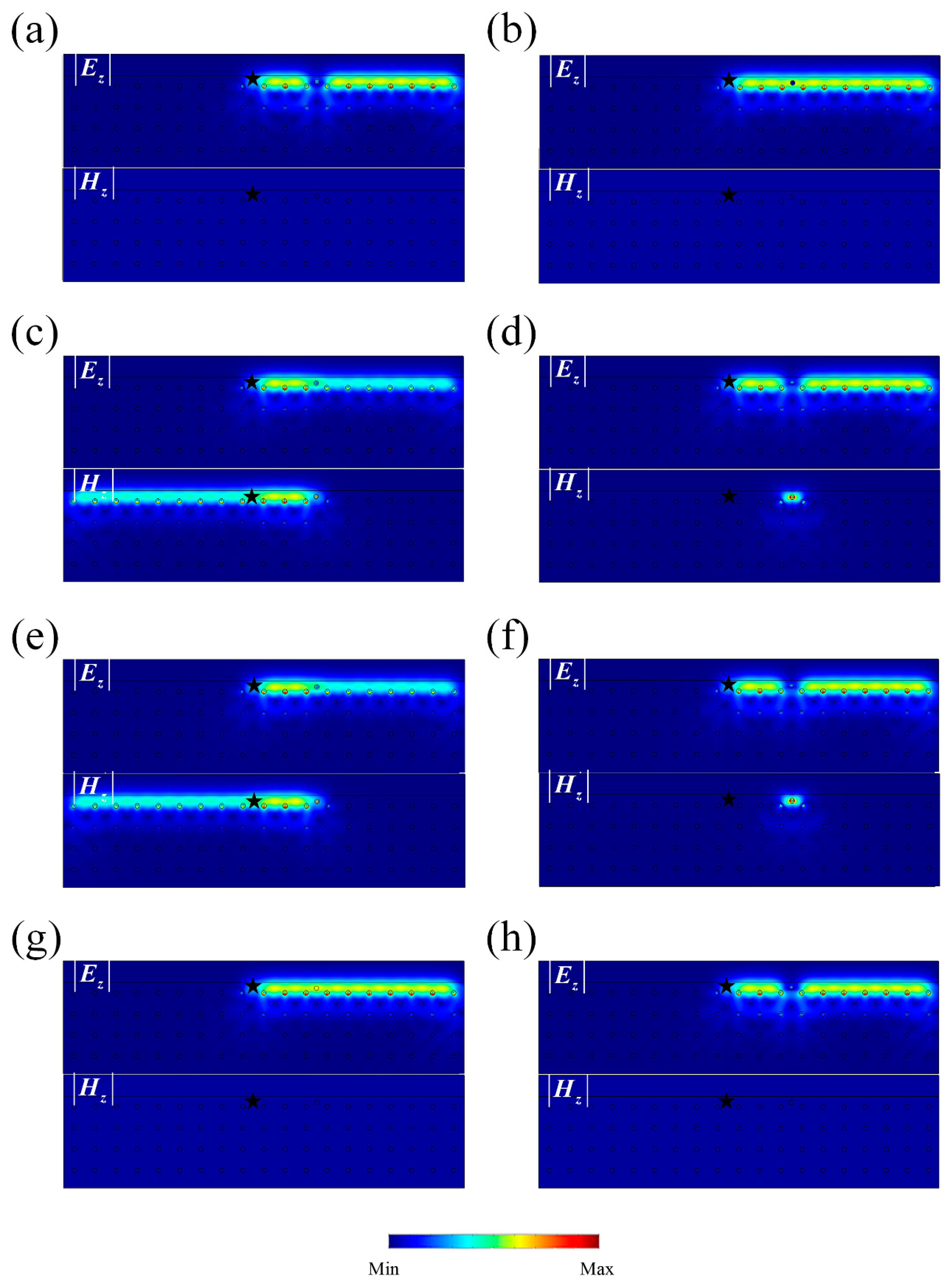
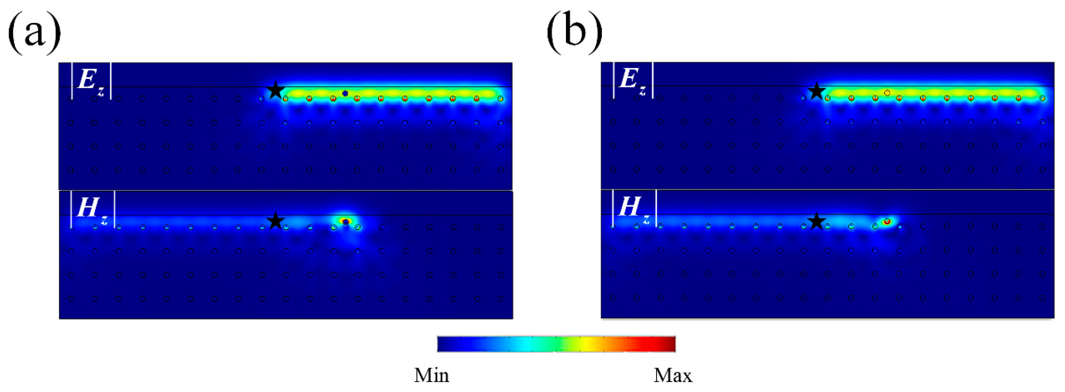
3.2. Pseudo TRS and Robustness of the One-Way Edge State

In this section, we test the robustness of our system. There are two basic types of symmetries in PTI systems, T b and T p , which are both composed of a Pauli matrix and complex conjugate operator, e.g., T p = i σ y K and T b = σ z K . Following this principle, we can also construct other two kinds of symmetry operators, T x = σ x K and T I = K , as shown in the first row of Table 1. To check the robustness of the system, a complete set of impurities are used and their character Hamiltonian H ^ s are shown in the first column of Table 1. The commutations between H ^ and T are listed in the table. Here, circle marks indicate that the commutation result is zero while cross marks indicate a non-zero result. The realization of the eight kinds of impurities are listed in the last column of Table 1. The lossless condition, ε = ε , μ = μ , and ξ = ζ , is assumed. Following Table 1, we study the robustness (the backscattering-immune property) of our PTI against the eight kinds of impurities as shown in Figure 3. An E z source is set at the interface indicated by a black star and the cylinder impurity ( r = 0.11 a ) is placed at the center of waveguide. If there is backscattering, the corresponding impurity is considered to break the robustness.
As shown in Figure 3a,d,f,h, E z wave propagates in one direction against impurities without any backscattering. Their corresponding character Hamiltonians all commute with the pseudo TRS T p = i σ y K , as shown in Table 1. This means that an impurity with T p will retain the robustness. In other words, the pseudo TRS is sufficient to ensure the robustness. It should be noticed that the impurity with H ^ = I represents the cavity, impedance-matching dielectric impurities and H ^ = i σ z represents the our-of-order arrangement of the lattice, which are all conventional impurities. A principle which should be clarified is that when we say the robustness is protected by a certain symmetry, we mean that the symmetry is not only sufficient but is also necessary for the robustness.
For the impurities without pseudo TRS, Figure 3c,e show strong backscattering properties, which match the commutation analysis of T p in Table 1 ( [ σ x , T p ] 0 and [ σ y , T p ] 0 ). Finally, there remain two special cases in Figure 3b,g. Although no backscattering can be found, the commutations between their character Hamiltonians and T p are non-zero. The reason is that impurities with H ^ i I = i I (Figure 3b) and H ^ z = σ z (Figure 3g) will not exchange TE and TM modes. Therefore, no H z backscattering can be observed.
To further prove our conclusion, we mixed impurities H ^ i I = i I and H ^ z = σ z with H ^ i x = i σ x . H ^ i x itself cannot break the robustness, as shown in Figure 3d, but will exchange TE and TM modes due to the non-diagonal terms. The corresponding constitutive parameters are chosen as
ε = μ = [ 0 14 i 0 14 i 0 0 0 0 14 ] , ξ = ζ = [ 0 12.4 i 0 12.4 i 0 0 0 0 0 ] ,
and
ε = d i a g { 14 , 14 , 1 } , μ = d i a g { 14 , 14 , 15 } , ξ = ζ = [ 0 12.4 i 0 12.4 i 0 0 0 0 0 ]
The backscattering results are shown in Figure 4a,b, which means H ^ i I = i I and H ^ z = σ z can induce backscattering. Finally, we obtain get the conclusion that the pseudo TRS T p is not only a sufficient condition but also a necessary condition for protecting the robust propagation of PTIs.
On the other hand, the bosonic TRS is not a necessary condition, and its operator T b has different mathematic forms under different bases. For instance, in our system TE/TM is the eigen state, leading to the result that T b = T z is the corresponding bosonic TRS operator ( E z E z ,   H z H z under time-reversal operation). The Hamiltonian of our proposed PTI (Equation (1)) does not commutate with T z but commutates with T p . Thus, there is no bosonic TRS but only a pseudo TRS in our system as well as a perviously reported left and right circular polarization-based PTI [26]. Otherwise, if we choose another eigen state such as TE + TM/TE − TM [18], the corresponding TRS operator changes to the form of T x . The Hamiltonian of such polarization-based PTIs both commutate with T x and T p . To clarify different kinds of T and judge which is the one responsible for the robustness, we should test all eight kinds of impurities.

3.3. Theoretical Model of Dirac Degeneracy via Tight Binding Approximation and Spin Chern Number

Here, we apply the tight binding approximation method to construct an analytical model via the low-energy effective Hamiltonian. For simplicity, TE and TM polarization can be treated independently. For the TE polarization, there are three types of eigen-modes, these being | s T E , | p x T E , and | p y T E , equivalent to an electric monopole and two electric dipole modes in an electronic system. We can define new p modes as the linear superposition of | p x T E and | p y T E : | p ± T E = ( | p x T E ± i | p y T E ) / 2 . By applying the perturbation theory and expanding the k-dependent Hamiltonian to the first order, we can obtain [26]
H T E = E 0 + m 0 τ z + v f ( k y τ x + k x τ y ) H 0
where τ x , τ y and τ z are Pauli matrices, E 0 is the energy origin point, m 0 is the mass term and v f represents the phase velocity near the Dirac point [26]. It is therefore evident that the Hamiltonian here is a Dirac equation.
The Hamiltonian of TM can be expressed in terms of the TE mode via symmetry operation on all eigen-modes. The Hamiltonian for the whole system can be expressed as
H = [ H 0 ( k ) 0 0 H 0 ( k ) ]
This is the same with as that in the BHZ (Bernevig-Hugues-Zhang) model of a two-dimensional electronic QSHE [6]. By solving the eigen equation Equation (5) [26], the dispersion of the edge states for our system can be determined as:
E = σ v f k y ,   σ = ± 1
The dispersion of the edge-states can thus be analytically obtained as shown in Figure 5, fitting well with the simulation data. In the calculation v f = 0.1153   m / s was chosen for the edge states.
We also numerically investigate the Berry curvature (BC) and spin Chern numbers [11] in our PTI system. Taking TM polarization for example, the BC can be calculated by Ref. [14]
B C ( k ) ( B C ( k ) ) z = ( k × A T M ( k ) ) z = ( k × ( E k | k | E k ) ) z ( k × ( d 2 r ε   E z ( k ) k E z ( k ) ) ) z
with the result shown in Figure 6a. The corresponding spin Chern number can be calculated by integration of the BC over the whole Brillouin zone C T M = ( 1 / 2 π ) B Z B C ( k ) d 2 k . The BC around the M points has positive values and contributes most to the summation, leading to C T M = 1 . On the contrary, the BC of TE polarization is negative near the M points as shown in Figure 6b, and the corresponding spin Chern number C T E = 1 . The final result C T M / T E = ± 1 further indicates the photonic QSHE appearing in our system [11]. It can be shown that the Z 2 invariant and spin Chern number yield equivalent descriptions [26,34].

4. Discussion

The QSHE in electronic systems is described by the Dirac equation, with T f 2 = 1 . According to the Kramers theorem, the single-particle eigen-mode of the Hamiltonian must have a degenerate partner. When one-way propagating electrons are backscattered by a nonmagnetic impurity, the two possible backscattering paths always interfere destructively, leading to perfect transmission [35]. Similarly, in our proposed PTI system, the T p operator with T p 2 = 1 means that rigorous Kramers double degeneracy can exist for photons as well. Therefore, the transportation robustness of the net polarization carried by photonic edge states is protected by such symmetry. Moreover, polarization-dependent edge states in our PTI are robust, as they can exist against all kinds of disorders and impurities that keep the pseudo TRS.
Although the homogenous gyrotropic material used in our PTI might not be available in nature, there are several ways to obtain the desirable effective gyrotropic response. First, an effective medium combining two sub-wavelength sized naturally-occurring gyroelectric and gyromagnetic materials [15] can be formed to mimic gyrotropic response. Photonic structure geometry can be further designed to achieve great flexibility when designing waveguide-based 2D photonic crystals [36]. Secondly, metamaterials can be applied and engineered to tailor electromagnetic responses, including magnetic resonance, electronic resonance, optical active chirality, and desirable gyrotropic responses from magneto-electric coupling [18,37]. Additionally, in some artificial multiferroic materials, a magnetic field could be applied to manipulate ferroelectric polarization, and vice versa. These effects could be leveraged to create a material system with the coexistence of off-diagonal terms in permittivity and permeability tensors [38].

5. Conclusions

In summary, our findings clarify the role of TRS and pseudo TRS in bosonic TI systems. Following the principle to construct a fermionic-like pseudo TRS, we have proposed a PTI with TE/TM polarizations as photonic spins. Backscattering immune propagation and polarization-dependent transportation can be achieved with a pair of conjugate gapless edge states. Based on a symmetry analysis using all eight possible types of impurities, we have definitively shown that a PTI is only protected by the pseudo TRS T p [39]. Moreover, analytic dispersion of edge states and numerically calculated spin Chern numbers have also been investigated to confirm the non-trivial topological property. Our work may find great potential applications such as in a polarization splitter for entangled photons [40], optical isolation, and polarization-dependent transportation. The roadmap we used to retrieve the constitutive relation of PTI components in this paper may pave the way for constructing some experimentally desirable PTIs and may be leveraged to create other types of bosonic TI.

Author Contributions

Conceptualization, C.H. and M.-H.L.; data curation, X.-C.S.; funding acquisition, C.H., M.-H.L., X.H., and Y.-F.C.; investigation, X.-C.S.; methodology, C.H.; software, X.-C.S.; supervision, M.-H.L. and Y.-F.C.; writing—original draft, X.-C.S.; writing—review & editing, C.H., X.-P.L., Y.Z., M.-H.L., X.H., and Y.-F.C.

Funding

The work was jointly supported by the National Key R&D Program of China (Grant Nos. 2017YFA0305100 and 2017YFA0303702) and the National Nature Science Foundation of China (Grant Nos. 11874196, 11890700, 11625418, 51732006, 51721001, and 51702152). X. Hu was supported by Grants-in-Aid for Scientific Research No.17H02913, Japan Society of Promotion of Science, and CREST JPMJCR18T4, Japan Science and Technology Agency.

Acknowledgments

We thank P. Nayar for helpful discussion.

Conflicts of Interest

The authors declare no conflict of interest.

References

  1. Klitzing, K.V.; Dorda, G.; Pepper, M. New method for high-accuracy determination of the fine-structure constant based on quantized Hall resistance. Phys. Rev. Lett. 1980, 45, 494–497. [Google Scholar] [CrossRef]
  2. Thouless, D.J.; Kohmoto, M.; Nightingale, M.P.; den Nijs, M. Quantized Hall conductance in a two-dimensional periodic potential. Phys. Rev. Lett. 1982, 49, 405–408. [Google Scholar] [CrossRef]
  3. Tsui, D.C.; Stormer, H.L.; Gossard, A.C. Two-dimensional magnetotransport in the extreme quantum limit. Phys. Rev. Lett. 1982, 48, 1559–1562. [Google Scholar] [CrossRef]
  4. Hatsugai, Y. Chern number and edge states in the integer quantum Hall effect. Phys. Rev. Lett. 1993, 71, 3697–3700. [Google Scholar] [CrossRef] [PubMed]
  5. Kane, C.L.; Mele, E.J. Z(2) topological order and the quantum spin Hall effect. Phys. Rev. Lett. 2005, 95, 146802. [Google Scholar] [CrossRef] [PubMed]
  6. Bernevig, B.A.; Hughes, T.L.; Zhang, S.-C. Quantum spin Hall effect and topological phase transition in HgTe quantum wells. Science 2006, 314, 1757–1761. [Google Scholar] [CrossRef] [PubMed]
  7. König, M.; Wiedmann, S.; Brüne, C.; Roth, A.; Buhmann, H.; Molenkamp, L.W.; Qi, X.-L.; Zhang, S.-C. Quantum spin Hall insulator state in HgTe quantum wells. Science 2007, 318, 766–770. [Google Scholar] [CrossRef] [PubMed]
  8. Hsieh, D.; Qian, D.; Wray, L.; Xia, Y.; Hor, Y.S.; Cava, R.J.; Hasan, M.Z. A topological Dirac insulator in a quantum spin Hall phase. Nature 2008, 452, 970–974. [Google Scholar] [CrossRef] [PubMed] [Green Version]
  9. Hasan, M.Z.; Kane, C.L. Colloquium: Topological insulators. Rev. Mod. Phys. 2010, 82, 3045–3067. [Google Scholar] [CrossRef]
  10. Qi, X.-L.; Zhang, S.-C. Topological insulators and superconductors. Rev. Mod. Phys. 2011, 83, 1057–1110. [Google Scholar] [CrossRef] [Green Version]
  11. Sheng, L.; Sheng, D.N.; Ting, C.S.; Haldane, F.D.M. Nondissipative spin Hall effect via quantized edge transport. Phys. Rev. Lett. 2005, 95, 136602. [Google Scholar] [CrossRef] [PubMed]
  12. Haldane, F.D.M.; Raghu, S. Possible realization of directional optical waveguides in photonic crystals with broken time-reversal symmetry. Phys. Rev. Lett. 2008, 100, 013904. [Google Scholar] [CrossRef] [PubMed]
  13. Raghu, S.; Haldane, F.D.M. Analogs of quantum-Hall-effect edge states in photonic crystals. Phys. Rev. A 2008, 78, 033834. [Google Scholar] [CrossRef]
  14. Wang, Z.; Chong, Y.D.; Joannopoulos, J.D.; Soljacic, M. Reflection-free one-way edge modes in a gyromagnetic photonic crystal. Phys. Rev. Lett. 2008, 100, 013905. [Google Scholar] [CrossRef] [PubMed]
  15. Wang, Z.; Chong, Y.; Joannopoulos, J.D.; Soljacic, M. Observation of unidirectional backscattering-immune topological electromagnetic states. Nature 2009, 461, 772–775. [Google Scholar] [CrossRef] [PubMed] [Green Version]
  16. Cayssol, J.; Dora, B.; Simon, F.; Moessner, R. Floquet topological insulators. Phys. Status Solidi Rapid Res. Lett. 2013, 7, 101–108. [Google Scholar] [CrossRef] [Green Version]
  17. Rechtsman, M.C.; Zeuner, J.M.; Plotnik, Y.; Lumer, Y.; Podolsky, D.; Dreisow, F.; Nolte, S.; Segev, M.; Szameit, A. Photonic Floquet topological insulators. Nature 2013, 496, 196–200. [Google Scholar] [CrossRef] [PubMed] [Green Version]
  18. Khanikaev, A.B.; Mousavi, S.H.; Tse, W.-K.; Kargarian, M.; MacDonald, A.H.; Shvets, G. Photonic topological insulators. Nat. Mater. 2013, 12, 233–239. [Google Scholar] [CrossRef] [PubMed]
  19. Hafezi, M.; Demler, E.A.; Lukin, M.D.; Taylor, J.M. Robust optical delay lines with topological protection. Nat. Phys. 2011, 7, 907–912. [Google Scholar] [CrossRef] [Green Version]
  20. Hafezi, M.; Mittal, S.; Fan, J.; Migdall, A.; Taylor, J.M. Imaging topological edge states in silicon photonics. Nat. Photonics 2013, 7, 1001–1005. [Google Scholar] [CrossRef] [Green Version]
  21. Ma, T.; Khanikaev, A.B.; Mousavi, S.H.; Shvets, G. Guiding electromagnetic waves around sharp corners: Topologically protected photonic transport in metawaveguides. Phys. Rev. Lett. 2015, 114, 127401. [Google Scholar] [CrossRef] [PubMed]
  22. Chen, W.-J.; Jiang, S.-J.; Chen, X.-D.; Zhu, B.; Zhou, L.; Dong, J.-W.; Chan, C.T. Experimental realization of photonic topological insulator in a uniaxial metacrystal waveguide. Nat. Commun. 2014, 5, 5782. [Google Scholar] [CrossRef] [PubMed] [Green Version]
  23. Wu, L.-H.; Hu, X. Scheme for Achieving a Topological Photonic Crystal by Using Dielectric Material. Phys. Rev. Lett. 2015, 114, 223901. [Google Scholar] [CrossRef] [PubMed]
  24. Yang, Y.; Xu, Y.F.; Xu, T.; Wang, H.-X.; Jiang, J.-H.; Hu, X.; Hang, Z.H. Visualization of a Unidirectional Electromagnetic Waveguide Using Topological Photonic Crystals Made of Dielectric Materials. Phys. Rev. Lett. 2018, 120, 217401. [Google Scholar] [CrossRef] [PubMed] [Green Version]
  25. Li, Y.; Sun, Y.; Zhu, W.; Guo, Z.; Jiang, J.; Kariyado, T.; Chen, H.; Hu, X. Topological LC-circuits based on microstrips and observation of electromagnetic modes with orbital angular momentum. Nat. Commun. 2018, 9, 4598. [Google Scholar] [CrossRef] [PubMed]
  26. He, C.; Sun, X.-C.; Liu, X.-P.; Lu, M.-H.; Chen, Y.; Feng, L.; Chen, Y.-F. Photonic topological insulator with broken time-reversal symmetry. Proc. Natl. Acad. Sci. USA 2016, 113, 4924–4928. [Google Scholar] [CrossRef] [PubMed]
  27. Cheng, X.; Jouvaud, C.; Ni, X.; Mousavi, S.H.; Genack, A.Z.; Khanikaev, A.B. Robust reconfigurable electromagnetic pathways within a photonic topological insulator. Nat. Mater. 2016, 15, 542–548. [Google Scholar] [CrossRef] [PubMed]
  28. Ochiai, T. Time-reversal-violating photonic topological insulators with helical edge states. J. Phys. Soc. Jpn. 2015, 84, 054401. [Google Scholar] [CrossRef]
  29. Kong, J.A. Theory of Electromagnetic Waves; John Wiley & Sons Inc.: Hoboken, NJ, USA, 1975. [Google Scholar]
  30. Pozar, D.M. Microwave Engineering, 2nd ed.; John Wiley & Sons Inc.: Hoboken, NJ, USA, 1998. [Google Scholar]
  31. He, C.; Lu, M.-H.; Wan, W.-W.; Li, X.-F.; Chen, Y.-F. Influence of boundary conditions on the one-way edge modes in two-dimensional magneto-optical photonic crystals. Solid State Commun. 2010, 150, 1976–1979. [Google Scholar] [CrossRef]
  32. Ao, X.; Lin, Z.; Chan, C.T. One-way edge mode in a magneto-optical honeycomb photonic crystal. Phys. Rev. B 2009, 80, 033105. [Google Scholar] [CrossRef]
  33. Poo, Y.; Wu, R.-X.; Lin, Z.; Yang, Y.; Chan, C.T. Experimental realization of self-guiding unidirectional electromagnetic edge states. Phys. Rev. Lett. 2011, 106, 093903. [Google Scholar] [CrossRef] [PubMed]
  34. Fu, L.; Kane, C.L. Topological insulators with inversion symmetry. Phys. Rev. B 2007, 76, 045302. [Google Scholar] [CrossRef]
  35. Qi, X.-L.; Zhang, S.-C. The quantum spin Hall effect and topological insulators. Phys. Today 2010, 63, 33–38. [Google Scholar] [CrossRef] [Green Version]
  36. Feng, L.; Xu, Y.-L.; Fegadolli, W.S.; Lu, M.-H.; Oliveira, J.E.B.; Almeida, V.R.; Chen, Y.-F.; Scherer, A. Experimental demonstration of a unidirectional reflectionless parity-time metamaterial at optical frequencies. Nat. Mater. 2013, 12, 108–113. [Google Scholar] [CrossRef] [PubMed]
  37. Shelby, R.A.; Smith, D.R.; Schultz, S. Experimental verification of a negative index of refraction. Science 2001, 292, 77–79. [Google Scholar] [CrossRef] [PubMed]
  38. Cheong, S.-W.; Mostovoy, M. Multiferroics: A magnetic twist for ferroelectricity. Nat. Mater. 2007, 6, 13–20. [Google Scholar] [CrossRef] [PubMed]
  39. Susstrunk, R.; Huber, S.D. PHYSICS. Observation of phononic helical edge states in a mechanical topological insulator. Science 2015, 349, 47–50. [Google Scholar] [CrossRef] [PubMed]
  40. Chen, W.; Shen, R.; Sheng, L.; Wang, B.G.; Xing, D.Y. Electron entanglement detected by quantum spin Hall systems. Phys. Rev. Lett. 2012, 109, 036802. [Google Scholar] [CrossRef] [PubMed]
Figure 1. Bloch sphere and energy band of supercell. (a) Choose | β | 2 | α | 2 , 2 Re ( α β ) , and 2 Im ( α β ) of the two-component vector ( α , β ) T , e.g., T E = ( 1 , 0 ) T , T M = ( 0 , 1 ) T , to be the x-, y-, and z-components of 3D space. The polarizations transverse electric (TE)/transverse magnetic (TM), TE + TM/TE − TM, and TE + iTM/TE − iTM are the unit vectors on three main axes. (b) The projected band structures of the photonic topological insulator (PTI). Gapless edge states are denoted by green and red dotted lines. (c) and (d) correspond to the field (both electric and magnetic) distribution of points c and d in Figure 1b, respectively. The color represents the value of the E z or H z .
Crystals 09 00137 g001
Figure 2. Energy flow of a “ring-shaped” structure. (a) A schematic of the total energy flow in a ring-shaped PTI. (b) The net zero energy flow for the TE and TM modes combined. (c) The clockwise propagating energy flow of the TM mode. (d) The anti-clockwise propagating energy flow of the TE mode. The white bar represents the excitation source. The color on site represents the amplitude of the energy flow. Red (green) arrows represent the flow direction of the TM (TE) mode.
Crystals 09 00137 g002
Figure 3. Field distribution with impurities. (ah) Field distribution with impurities shown in Table 1. The black star presents an E z incidence point source while the impurity is set as a circle. Each upper picture shows | E z | distribution and the lower one shows | H z | distribution. The color on site represents the amplitude of | E z | or | H z | . All of the backscattering phenomenon match the commutation results in Table 1, except for (b) H ^ i I and (g) H ^ z .
Crystals 09 00137 g003
Figure 4. Field distribution with mixed impurities. We mixed impurities with character Hamiltonians H ^ i I = i I and H ^ z = σ z with H ^ i x = i σ x . Field distribution with impurities (a) H ^ i I + i x and (b) H ^ z + i x . It can be seen that by exchanging TE and TM modes, H ^ i I and H ^ z .
Crystals 09 00137 g004
Figure 5. The dispersion relation for edge states. The solid lines and open circles represent the theoretical results according to Equation (6) and the simulation data, respectively.
Crystals 09 00137 g005
Figure 6. The Berry curvature of TE and TM modes. (a) and (b) are TM and TE Berry curvatures, respectively. It can be seen that the wave vector around the M points contribute most to the Berry phase.
Crystals 09 00137 g006
Table 1. Commutation results between all Hamiltonian and symmetry operators. The symmetry type of each Hamiltonian (a two by two complex matrix) is determined via its constitutive equation (the last column). We list all kinds of commutation results between the Hamiltonians and four symmetry operators (three Pauli matrices and one identity matrix with a complex conjugate operator). Circle marks mean commutation while cross marks mean non-commutation.
T ^ T p = i σ y K T x = σ x K T z = σ z K T I = K Constitutive   Parameters   ε ,   μ ,   ξ ,   ζ   e . g . ,
H ^
I (a) ε = μ = 14
i I (b) ε = μ = [ 0 12.4 i 0 12.4 i 0 0 0 0 14 ]
σ x (c) ε = μ = 14 , ξ = ζ = d i a g { 0 , 0 , 14 }
i σ x (d) ε = μ = 14 , ξ = ζ = [ 0 12.4 i 0 12.4 i 0 0 0 0 0 ]
σ y (e) ε = μ = 14 , ξ = ζ = d i a g { 0 , 0 , 14 i }
i σ y (f) ε = μ = 14 , ξ = ζ = [ 0 12.4 0 12.4 0 0 0 0 0 ]
σ z (g) ε = 1 , μ = 14
i σ z (h) ε = [ 14 12.4 i 0 12.4 i 14 0 0 0 15 ] , μ = [ 14 12.4 i 0 12.4 i 14 0 0 0 15 ]

