Article

Dissimilar Infrared Brazing of CoCrFe(Mn)Ni Equiatomic High Entropy Alloys and 316 Stainless Steel

1
Department of Materials Science and Engineering, National Taiwan University, Taipei 106, Taiwan
2
Department of Mechanical Engineering, National Taiwan University, Taipei 106, Taiwan
*
Author to whom correspondence should be addressed.
Crystals 2019, 9(10), 518; https://doi.org/10.3390/cryst9100518
Submission received: 6 September 2019 / Revised: 2 October 2019 / Accepted: 8 October 2019 / Published: 9 October 2019
(This article belongs to the Special Issue Mechanical and Microstructural Characterization of Metals and Alloys)

Abstract

:
Dissimilar infrared brazing of CoCrFeMnNi/CoCrFeNi equiatomic high entropy alloys and 316 stainless steel using MBF601 and BNi-2 foils was evaluated. The wetting angles of the two fillers at 50 °C above their liquidus temperatures on the three substrates were below 40 degrees. The CoCrFeMnNi/316 SS joint had the highest shear strength of 361 MPa with BNi-2 filler brazing at 1020 °C for 180 s, and fractured at the CrB compound in the joint. The CoCrFeMnNi/MBF601/316 SS joint contained a CoCrFeMnNi-based matrix, phosphides and B-containing compounds. The CoCrFeNi/316 SS joint had the highest shear strength of 374 MPa when brazed with BNi-2 filler at 1020 °C for 600 s, and fractured at the CrB in the joint. The CoCrFeNi/MBF601/316 SS joint consisted of a (Fe,Ni)-rich matrix, phosphides and B/Cr/Fe/P compounds, and the highest shear strength of 324 MPa was achieved when it was brazed at 1080 °C for 600 s.

1. Introduction

High entropy alloys (HEAs), in which multiple principal elements are chosen as the base elements, were first reported in 2004 [1,2,3,4]. These alloys are called multi-principal element alloys (MPEAs) or complex concentrated alloys (CCAs). Many studies have shown that these alloy systems have many interesting and outstanding properties [5,6,7,8,9,10,11,12,13,14,15,16,17,18]. The CoCrFeMnNi HEA was first reported by Cantor [1]. This HEA was reported to be a solid solution with a face-centered cubic (FCC) structure at high temperatures [19], and to have excellent workability, ductility and toughness at cryogenic temperatures [20,21,22]. However, the Mn-containing HEA suffers from poor oxidation resistance and the high vapor pressure of the Mn ingredient [23,24]. It is difficult to cast and easily becomes oxidized. Additionally, the CoCrFeMnNi HEA was reported to form brittle Cr-rich, FeCo and MnNi intermetallics when heat treated below 700 °C [25,26,27,28,29,30]. In contrast, the CoCrFeNi alloy was also reported to have a FCC structure and good mechanical properties, just like the CoCrFeMnNi HEA, except for a higher cost [24,31,32,33,34]. It is well known that alloys with a FCC structure are free of ductile to brittle transition behavior at low temperatures. Therefore, both the CoCrFeMnNi and CoCrFeNi HEAs are considered to be potential candidates for cryogenic applications.
The joining of HEAs is crucial in the application of such new alloys for industrial applications. There are many studies on welding HEAs [35,36,37]. Good mechanical properties have been achieved in previous studies [38,39,40]. However, very limited researches are focused on brazing HEAs [41]. In comparison with welding, the major advantage of brazing is the dissimilar joining of two alloys with a huge difference in melting points [42,43]. In other words, brazing is usually applied for cases not suitable for welding.
Compared with Cu- and Ag-based fillers, Ni-based filler metals have the advantages of higher strength and excellent corrosion resistance, suitable for brazing HEAs [41,44]. The BNi-2 braze is a traditional Ni-based braze alloyed with B and Si. In contrast, MBF601 is primarily alloyed with P. They are potential candidates in brazing stainless steel and HEAs [41,44,45]. Similar infrared brazing of the CoCrFeMnNi HEA has been reported [41]. Both the BNi-2 and MBF601 filler metals can wet the CoCrFeMnNi substrate well, and the maximum shear strength exceeds 300 MPa. In this study, infrared dissimilar brazing is used to join the CoCrFeMnNi/CoCrFeNi HEAs and 316 SS with BNi-2 and MBF601 filler metals. The wettability, evolution of the microstructure and the shear strengths of selected joints are investigated.

2. Materials and Methods

Both CoCrFeMnNi and CoCrFeNi ingots of approximately 100 g were made by VAR (vacuum arc remelter) with cobalt, chromium, iron, nickel raw materials and manganese–nickel master alloy (50–50 in wt%). The purity of these raw materials and master alloy was above 99.9 wt%. The manganese–nickel master alloy was used to reduce the evaporation of manganese during vacuum arc remelting. The ingots were remelted at least six times and subsequently homogenized at 1200 °C for 24 h. The solidus temperatures of the CoCrFeMnNi and CoCrFeNi HEAs are 1334 °C and 1444 °C, respectively [46]. 1200 °C is the temperature just below the lower solidus temperature, and it was selected in many other studies [24,25,26]. The CoCrFeMnNi and CoCrFeNi ingots were cold-rolled into plates of 3.5 mm thickness. The nominal composition of the 316 stainless steel (316 SS) in wt% was 0.08 C, 17 Cr, 12 Ni, 2.5 Mo and Fe balance. Specimens of 15 × 7 × 3.5 mm3 were cut from the CoCrFeMnNi, CoCrFeNi and 316 SS plates by wire electrical discharge machining for wetting angle measurements, microstructural observations and shear tests. BNi-2 (Ni-7Cr-4.5Si-3.125B-3Fe, wt%) and MBF601 (Ni-32Fe-16Cr-1.5Mo-1.5Si-6P-0.5B, wt%) filler foils of 50 and 38 μm thickness, respectively, were purchased from Prince & Izant Company (OH, USA) and Metglas Inc. (SC, USA), respectively. The liquidus temperature of BNi-2 is 998 °C, and that of MBF601 is 1030 °C [44].
In the sessile drop test, BNi-2 and MBF601 filler balls weighing approximately 0.15 g were prepared by VAR [47]. An infrared furnace with a vacuum of 5 × 10⁻⁵ mbar was applied for dynamic wetting angle measurements. The selection of the brazing temperature was based on the liquidus temperature of the braze alloy. For instance, the liquidus temperature of BNi-2 filler is 998 °C, and 1080 °C is too high to perform the test. Therefore, 1080 °C was not performed in the experiment. The temperatures used in this study were 20 °C and 50 °C above the liquidus temperatures of the filler metals. The test conditions of the dynamic wetting angle measurements were 1020 °C and 1050 °C for the BNi-2 filler and 1050 °C and 1080 °C for the MBF601 filler. All the holding time periods were 300 s. The target of this study was to optimize the conditions in the dissimilar brazing of HEAs and 316 stainless steel.
The heating rate of the infrared furnace was kept at 15 °C/s, which is the same as previous studies [41,48]. A vacuum of 5 × 10⁻³ Pa was employed for brazing. The brazing conditions for the shear tests and microstructural observations are listed in Table 1. Figure 1 presents schematic diagrams of specimens fixed in graphite fixtures for microstructural observations and shear tests, respectively.
The fractured surfaces, cross-sections of joints and shear test specimens were observed with a field emission scanning electron microscope (FESEM, NOVA NANO 450, FEI Corp., OR, USA) and the quantitative chemical compositions of the brazed specimens were examined with an electron probe microanalyzer (EPMA, JXA-8200, JEOL, Tokyo, Japan) equipped with a wavelength dispersive spectroscope (WDS). Shear tests were performed with a universal tensile test machine (AG-IS, Shimadzu Corp., Kyoto, Japan) with a constant compressive strain rate of 0.0167 mm/s. Three brazed specimens were shear tested to obtain the average shear strength for each brazing condition. Selected fracture surfaces were examined with a Rigaku TTRAX III monochromatized X-ray diffractometer (XRD) for structural analyses.

3. Results and Discussion

3.1. Wetting Behavior

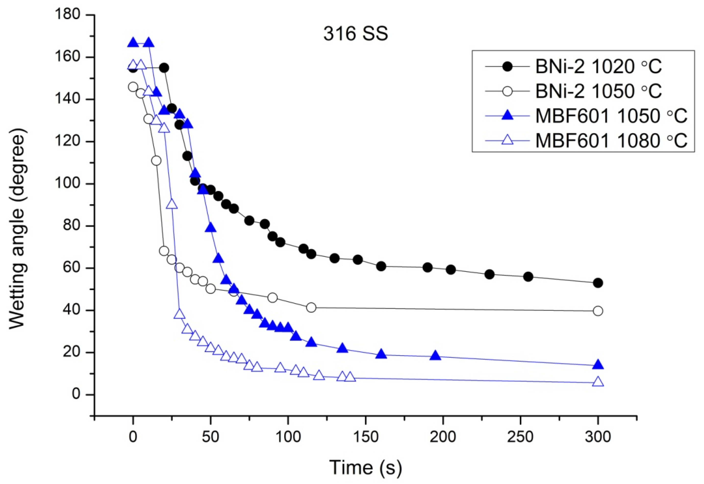
Figure 2 shows the dynamic wetting angle results of BNi-2 and MBF601 filler alloys on 316 SS substrate. For the BNi-2 filler metal at 1020 °C, the wetting angle remained at 155 degrees for the first 20 s and then it fell quickly to 70 degrees at 100 s before decreasing slowly to 53 degrees at 300 s. The wetting angle of the BNi-2 filler metal at 1050 °C fell quickly to 68 degrees in the first 20 s and then decreased slowly to 40 degrees at 300 s. For the MBF601 filler metal at 1050 °C, the wetting angle was 166 degrees at the beginning and fell quickly to 30 degrees at 100 s, after which it decreased slowly to 14 degrees at 300 s. At 1080 °C, the wetting angle was 155 degrees at first, dropped fast to 34 degrees at 30 s and then fell continuously to 6 degrees at 300 s.
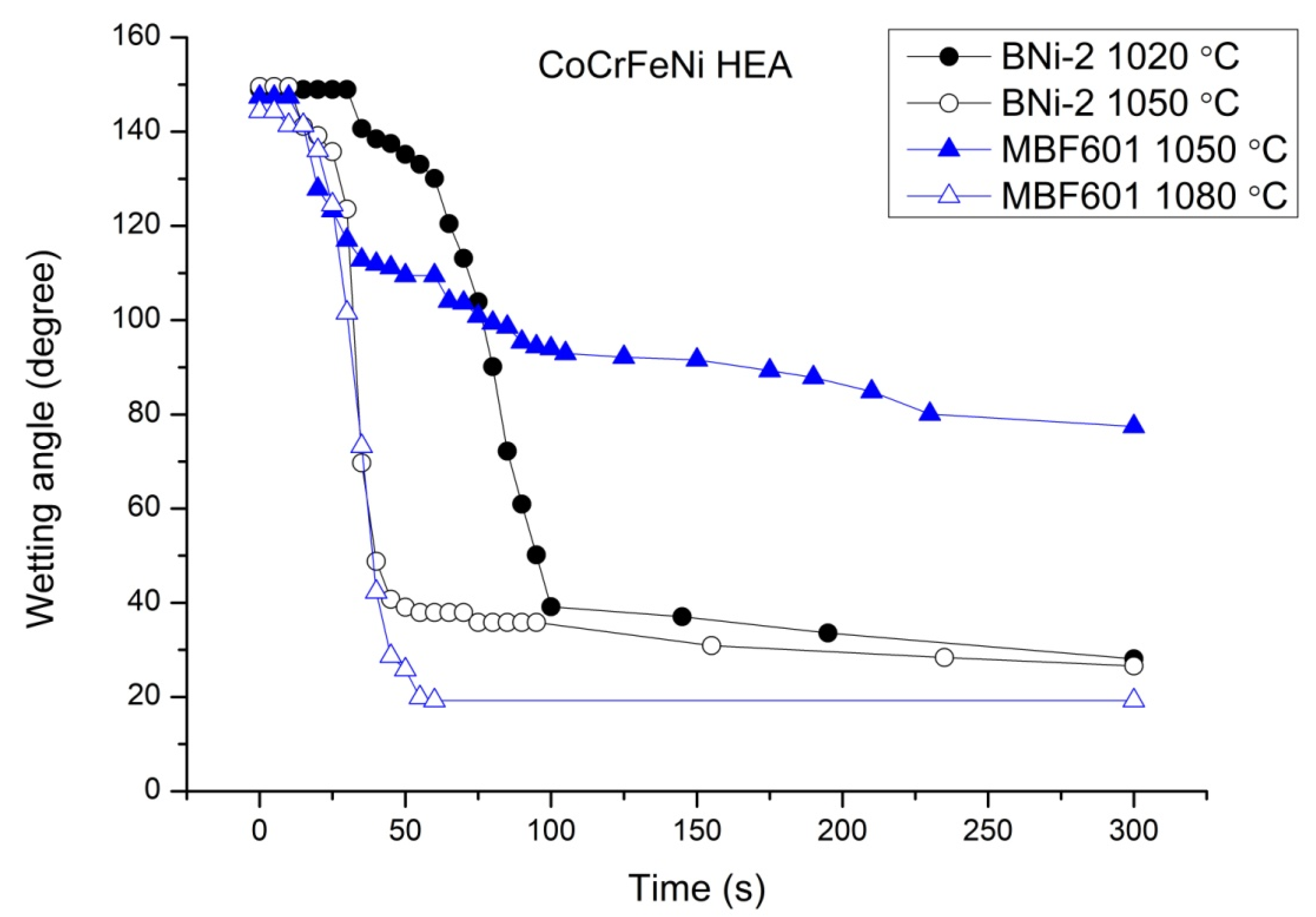
Figure 3 shows the dynamic wetting angles of BNi-2 and MBF601 fillers on the CoCrFeNi substrate. The wetting angle of the BNi-2 filler metal at 1020 °C remained at 149 degrees for the first 30 s, dropped to 40 degrees at 100 s and fell to 28 degrees at 300 s. For the BNi-2 filler metal at 1050 °C, the wetting angle remained at 149 degrees for the first 10 s and dropped to 40 degrees at 50 s before reaching 26 degrees at 300 s. The wettability of the MBF601 filler metal at 1050 °C was not good—the wetting angle was 147 degrees for the first 10 s, after which it dropped to 110 degrees at 50 s before reaching 77 degrees at 300 s. The wetting angle at 1080 °C was 144 degrees at first, dropped to 28 degrees at 45 s and reached 19 degrees at 300 s.
There were rapid/slow changes in the wetting angles of Figure 2 and Figure 3. The initial wetting of the braze melt is strongly related to rapid solid/liquid interfacial reaction at the early stage of the wetting test. The wetting angle was stabilized by increasing the test time because the mass transport of elements is confined by diffusion. Much slower changes in wetting angles were observed in Figure 2 and Figure 3.
The BNi-2 filler metal wet the CoCrFeNi substrate well at both 1020 °C and 1050 °C, but its wettability was poor on 316 SS substrate. The MBF601 filler metal wet 316 SS well at 1050 °C and 1080 °C and wet CoCrFeNi well at 1080 °C, but the wettability was poor at 1050 °C. In a previous study [41], the wettability of the BNi-2 and MBF601 filler metals on the CoCrFeMnNi HEA was investigated, and the wetting angles of the BNi-2 filler metal at 1020 °C and 1050 °C were found to be 80 and 18 degrees at 300 s, respectively. For the MBF601 filler metal on the CoCrFeMnNi substrate, the wetting angles at 1050 °C and 1080 °C were 86 and 8 degrees at 300 s, respectively. Both the BNi-2 and MBF601 filler metals are nickel-based filler metals, which are applicable to brazing Fe/Ni/Co-based alloys [44]. Good wettability is also achieved by the interfacial reaction between the filler metal and substrate. This explains why the wettability was good on these three substrates at temperatures 50 °C above their liquidus temperatures.

3.2. CoCrFeMnNi/BNi-2/316 Infrared Joints

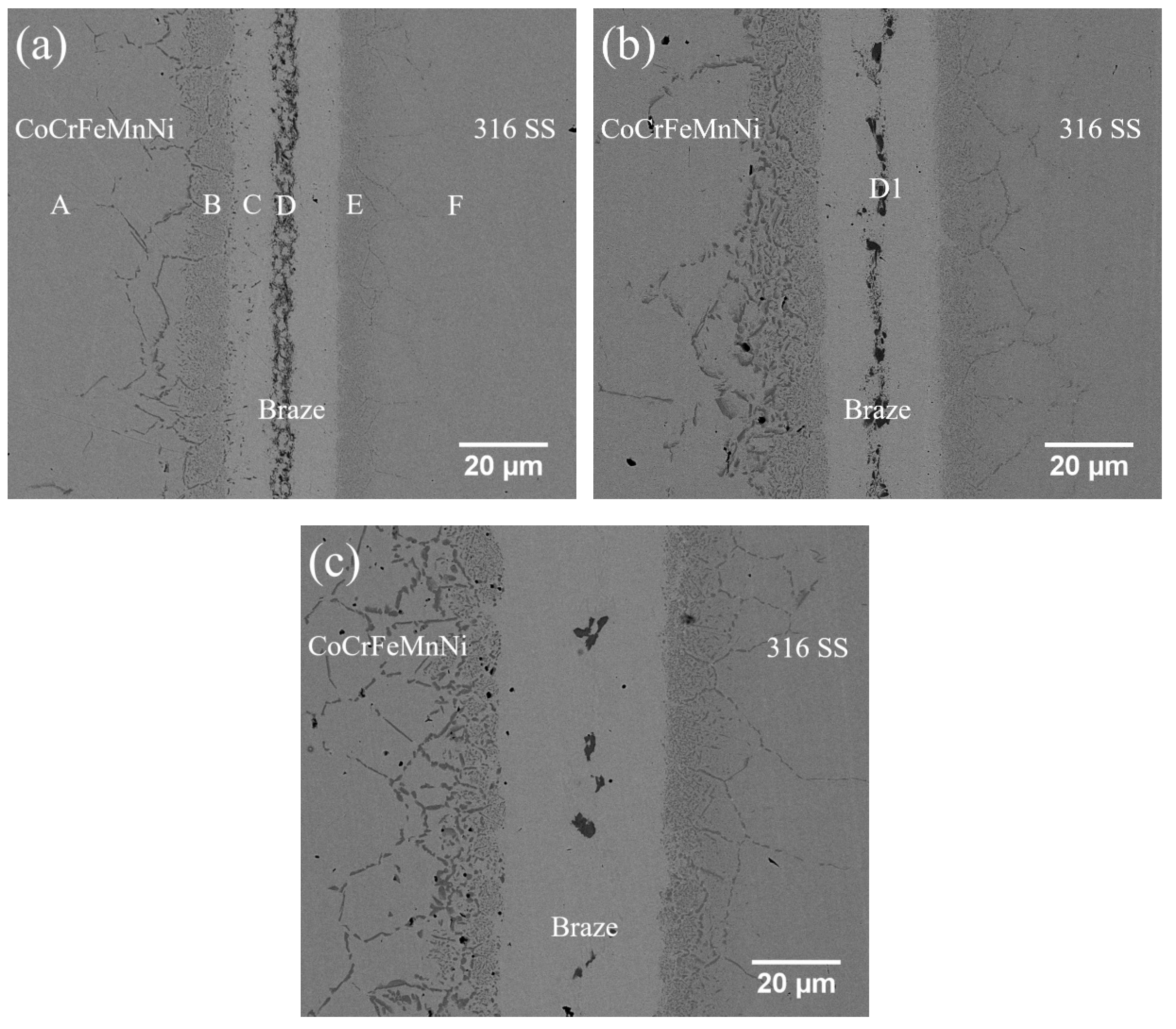
Figure 4 and Table 2 show BEIs (backscattered electron images) and the EPMA quantitative chemical analyses of joints infrared brazed at 1020 °C for 180 s and 600 s and at 1050 °C for 600 s. Both Ni-based filler alloys contain no carbon. The carbon content of 316 stainless steel is as low as 0.08 wt%. The solubility of carbon in Ni and γ-Fe is 0.6 wt% and 2.1 wt%, respectively [49]. There is no carbide formation in the experimental observation. In Figure 4a, the substrate marked A is the CoCrFeMnNi HEA and the substrate marked F is 316 SS. The joint brazed at 1020 °C for 180 s was dominated by a Ni-rich matrix, marked C, with continuous CrB, marked D, in the center of the brazed zone. There were two boride layers composed of fine borides at the interface between the braze and the two substrates. A few coarsened borides penetrated into the grain boundaries of both substrates. The boride layer on the CoCrFeMnNi side, marked B in Figure 4a, was thicker than that on the 316 SS side, marked E in Figure 4a. When the brazing time was increased from 180 s to 600 s, the amount of CrB in the center of the brazed zone diminished, but the CrB coarsened. However, the boride layers on both sides thickened. Increasing the brazing temperature from 1020 °C to 1050 °C caused the width of the Ni-rich matrix to thicken, and most of the CrB in the brazed zone disappeared. Boron atoms diffused into both substrates, and both boride layers became much thicker. Additionally, the borides growing along the grain boundaries penetrated much more deeply into the substrates.

3.3. CoCrFeMnNi/MBF601/316 Infrared Joints

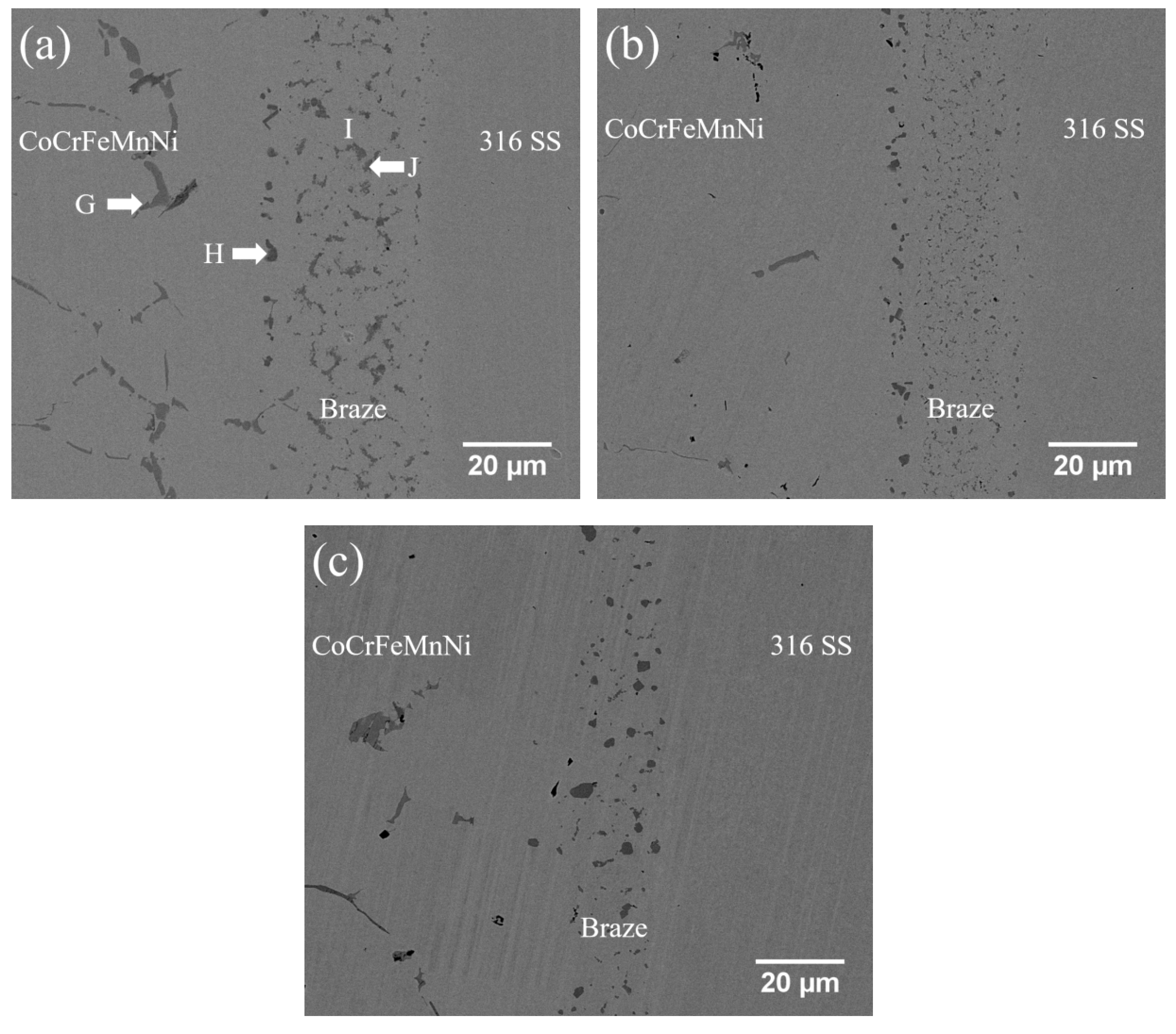
Figure 5 and Table 3 show the BEIs and the quantitative chemical analyses of CoCrFeMnNi/MBF601/316 joints infrared brazed at 1050 °C for 180 s and 600 s and at 1080 °C for 600 s. As shown in Figure 5a, the brazed joint was composed of a CoCrFeMnNi-based matrix, marked I, and some phosphides, marked J, and there was a row of B/Co/Cr/Fe/Mn/Ni/P compounds, marked H, between the CoCrFeMnNi substrate and the brazed zone. Also, some phosphides, marked G, penetrated into the grain boundaries of the CoCrFeMnNi substrate. When the brazing time at 1050 °C was increased from 180 s to 600 s, the phosphides in the brazed joint diminished in number and size. When the brazing temperature was changed from 1050 °C to 1080 °C, the phosphides in the brazed zone almost disappeared and the B/Co/Cr/Fe/Mn/Ni/P compounds became much larger.

3.4. CoCrFeNi/BNi-2/316 Infrared Joints

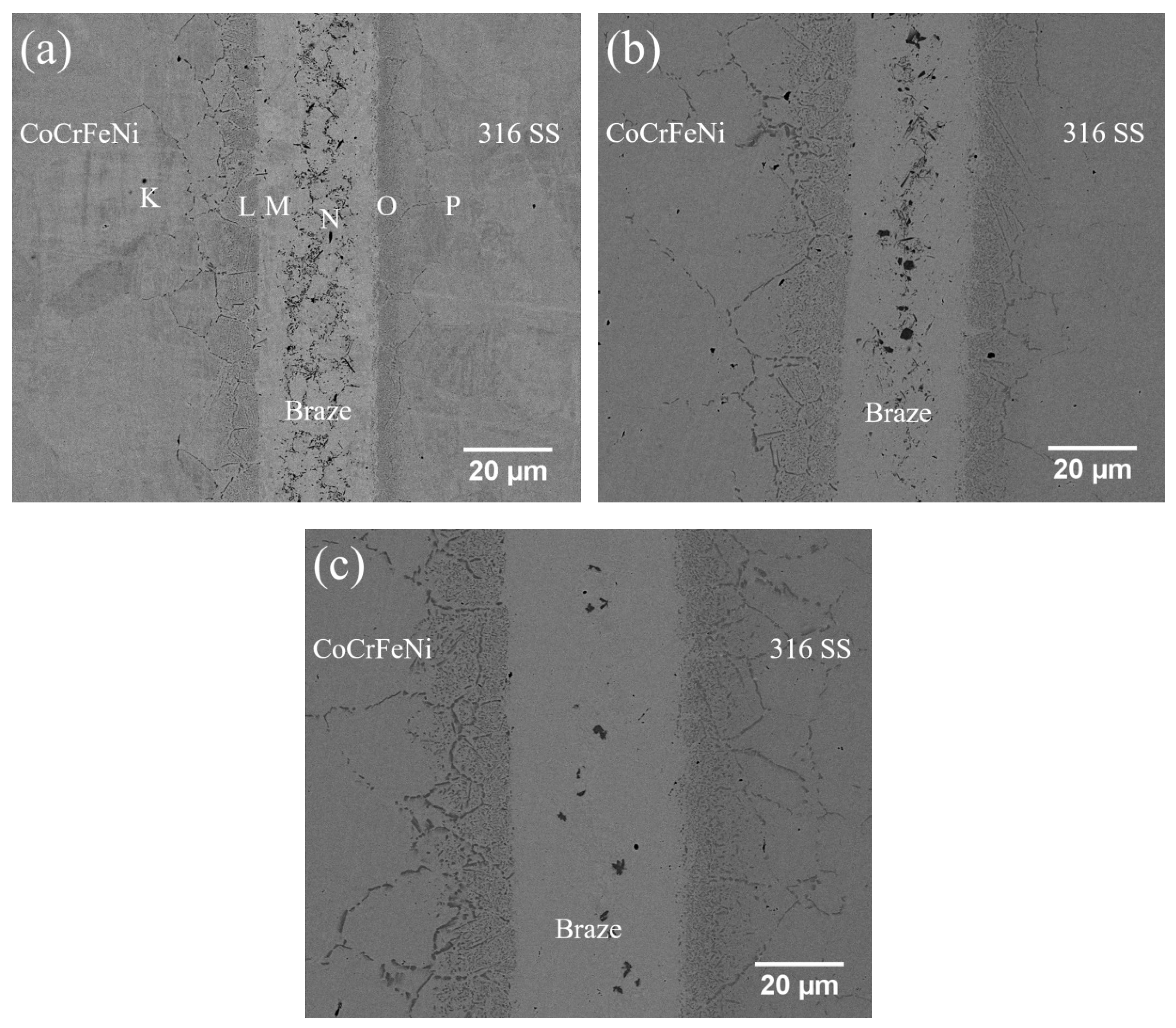
Figure 6 and Table 4 show the BEIs and quantitative chemical analyses of CoCrFeNi/BNi-2/316 joints infrared brazed at 1020 °C for 180 and 600 s and at 1050 °C for 600 s. In Figure 6a, the areas marked K and P are the CoCrFeNi and 316 SS substrates, respectively. The CoCrFeNi/BNi-2/316 joint infrared brazed at 1020 °C for 180 s was composed of a Ni-rich matrix and tiny CrB in the brazed zone, and there were interfacial boride layers between the braze and the two substrates. Some borides penetrated along the grain boundaries of the two substrates. When the brazing time was increased from 180 s to 600 s at 1020 °C, the amount of CrB in the brazed zone was reduced and the size coarsened, and the boride layer thickened. Increasing the brazing temperature from 1020 °C to 1050 °C reduced the amount of central CrB in the brazed zone due to the dissolution of the CrB at higher temperatures.

3.5. CoCrFeNi/MBF601/316 Infrared Joints

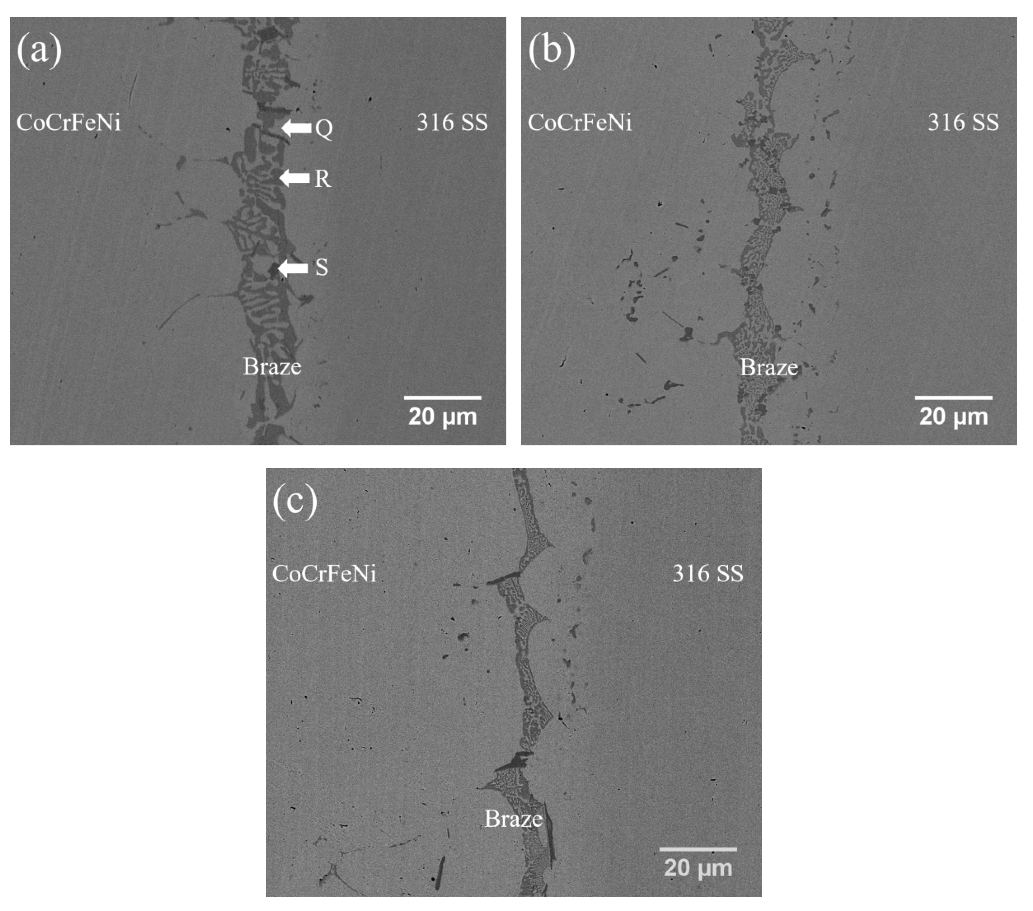
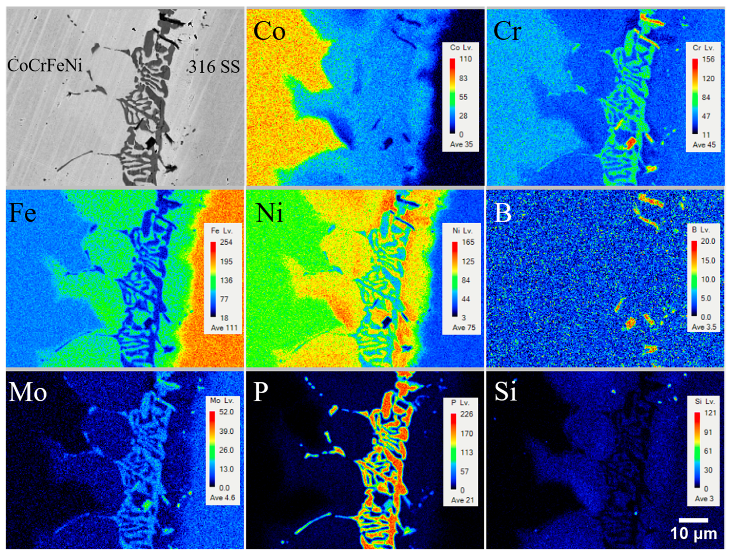
Figure 7 and Table 5 show the BEIs and quantitative chemical analyses of CoCrFeNi/MBF601/316 SS joints infrared brazed at 1050 °C for 180, 300, and 600 s and at 1080 °C for 600 s. The joint was composed of a (Fe,Ni)-rich matrix, marked Q, phosphides, marked R, and a few B/Cr/Fe/P compounds, marked S. Because the P cannot be alloyed into transition metals as high as 31.4 at%, the R phase in Figure 7a and Table 5 was categorized as a phosphide. Since BNi-2 contains no P, only boride was observed in the BNi-2 brazed joint. In contrast, the phosphide was observed in the MBF601 brazed joint because it was alloyed with high P content. Both are brittle compounds. Some phosphides penetrated into the grain boundaries of the CoCrFeNi and 316 SS substrates. The microstructure of the phosphides and the (Fe,Ni)-rich matrix appeared to be eutectic. However, no related phase diagrams are available. When the brazing time or temperature was increased, the thickness of the brazed zone decreased. It resulted from the dissolution of these compounds into both CoCrFeNi and 316 SS substrates. Figure 8 presents EPMA mappings to reveal the distributions of alloy elements in the brazed zone illustrated in Figure 7a. Elemental distributions along phases in Figure 8 are consistent with those in Figure 7a and Table 5.

3.6. Shear Strength and Failure Analyses

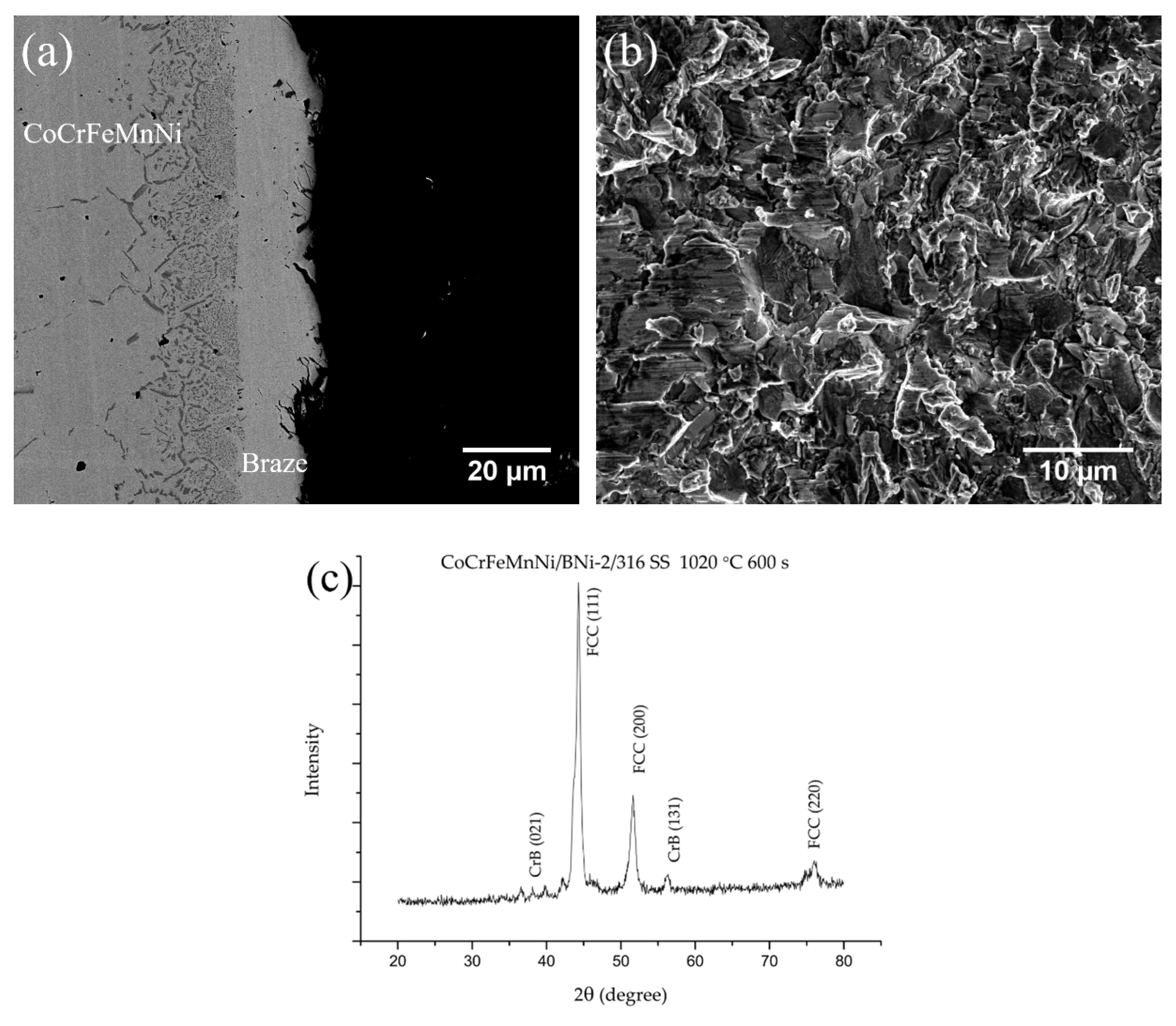
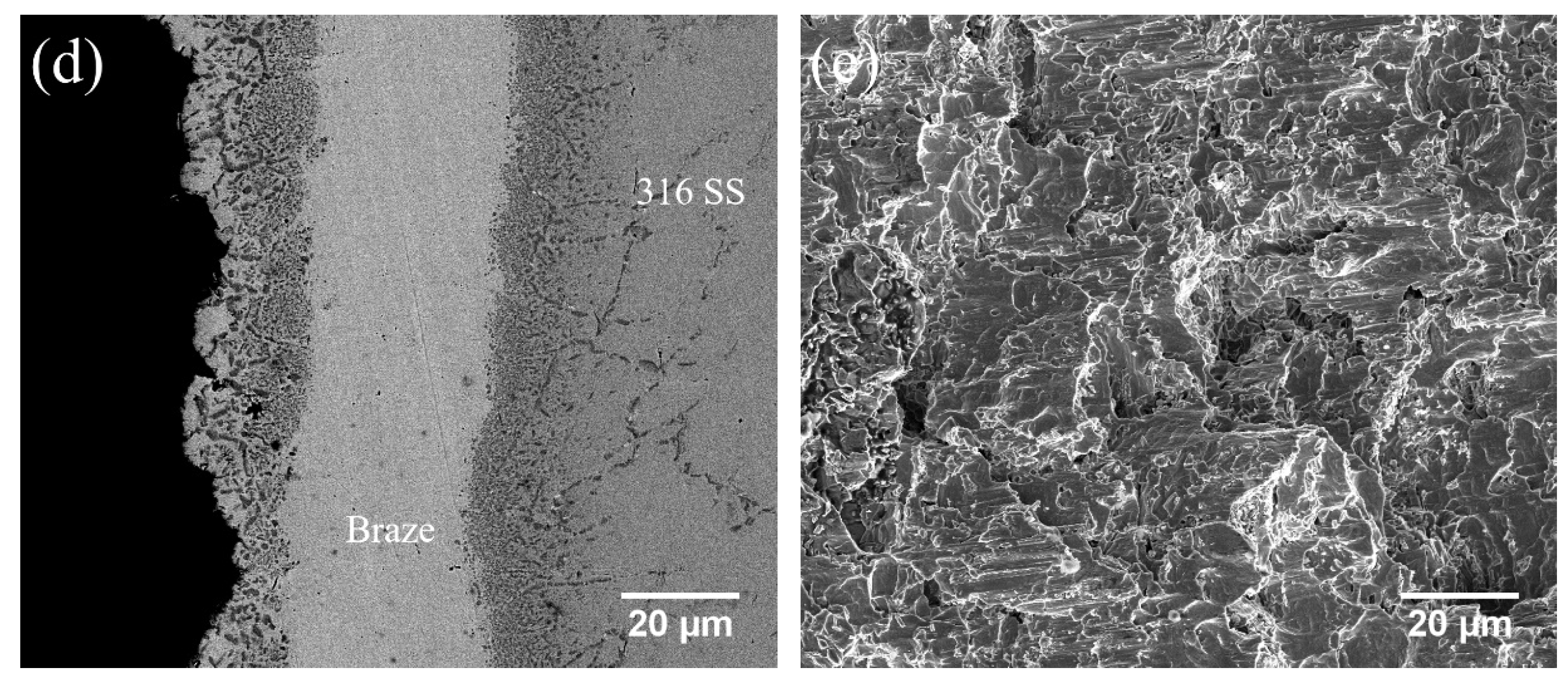
Table 6 shows that the average shear strengths and thicknesses of CoCrFeMnNi/BNi-2/316 SS joints brazed at 1020 °C for 180 and 600 s and at 1050 °C for 600 s were 361, 294 and 328 MPa, respectively. The joint brazed at 1020 °C for 600 s had the lowest shear strength. Figure 9 shows the BEI cross-sections and secondary electron image (SEI) fractographs of joints infrared brazed at 1020 °C for 600 s and at 1050 °C for 600 s, respectively. As can be seen in Figure 4b and Figure 9a, the fracture was located at the central continuous CrB in the brazed zone. The coarse central CrB in the joint resulted in decreased shear strength. The cleavage fracture surface is shown in Figure 9b. Figure 9c displays the XRD analysis of the fractured surface after the shear test. The fractured surfaces were primarily comprised of a FCC Ni-rich matrix and a CrB intermetallic compound for the BNi-2 brazed joint. When the brazing temperature was increased to 1050 °C, a fracture occurred in the coarsened interfacial boride layer on the CoCrFeMnNi side, as shown in Figure 9d, due to the dissolution of the central CrB into both substrates. Its fractograph indicated a brittle fracture, as shown in Figure 9e.
In a previous study of a similar infrared-brazed CoCrFeMnNi/BNi-2/CoCrFeMnNi joint, large CrB formed after brazing at 1020 °C for 180 s, and the joint had the lowest shear strength of 193 MPa [41]. The major alloying elements in 316 SS are Fe, Ni and Cr. These elements are also included in HEAs. The dissolution/reaction of these elements in 316 SS with filler metal are similar to HEAs. In the CoCrFeMnNi/BNi-2/316 SS dissimilar joint infrared brazed at 1020 °C for 180 s, there were no large CrB in the joint, and it had the highest shear strength of 361 MPa. The CrB became larger when the brazing time increased to 600 s. The fracture was usually located at the central large and continuous CrB borides, which caused the decrease in shear strength. It is worth mentioning that good wettability is a principal precondition to form a high-quality brazing joint. On the other hand, the formation and growth of interfacial compounds, e.g., CrB, was responsible for the fracture origin in the joints.
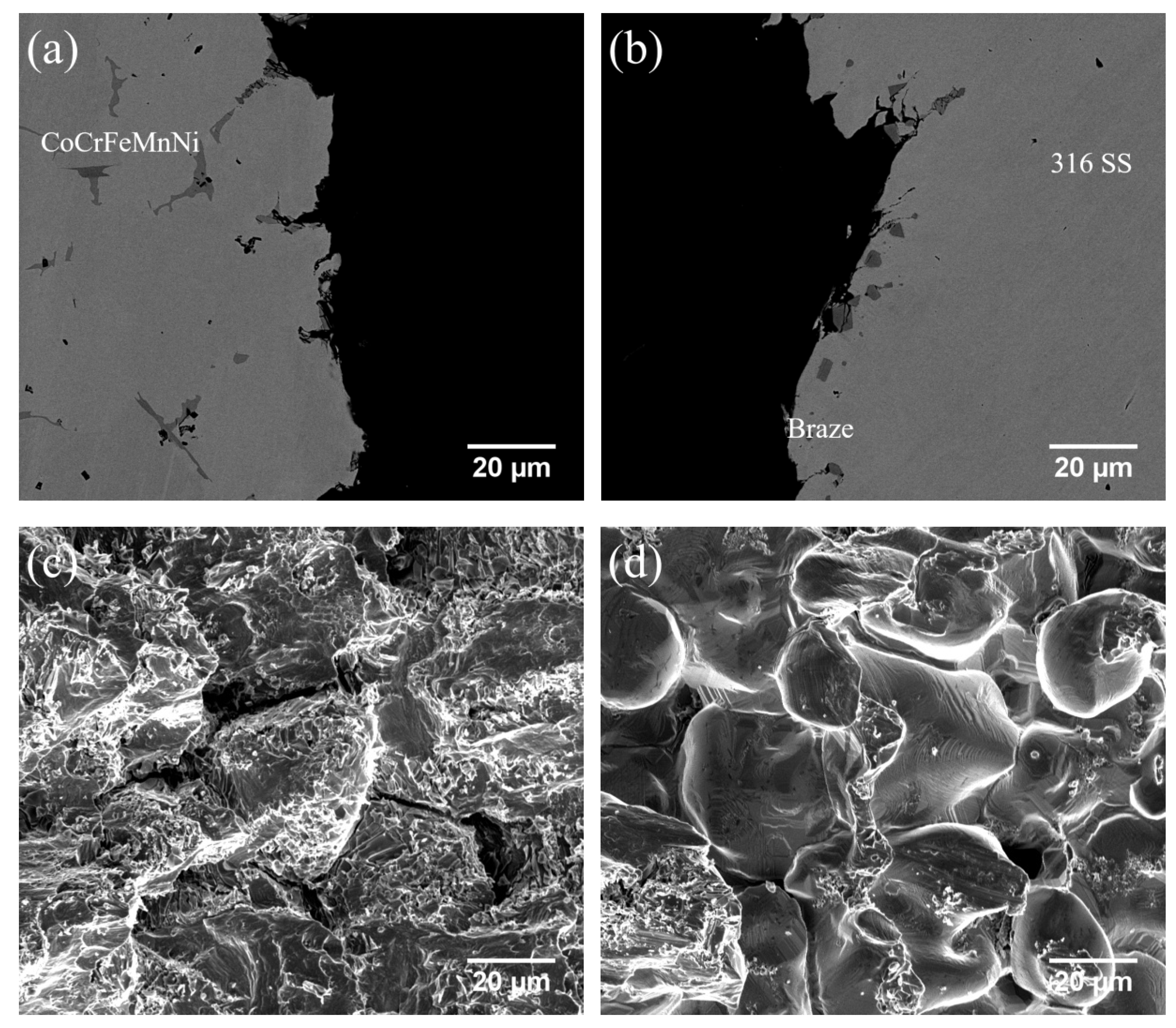
The shear strengths of CoCrFeMnNi/MBF601/316 SS infrared joints infrared brazed at 1050 °C for 180 and 600 s and at 1080 °C for 600 s were 216, 276 and 248 MPa, respectively. For the joint brazed at 1050 °C, the shear strength increased because of better wettability. The BEI cross-sections of a CoCrFeMnNi/MBF601/316 SS joint infrared brazed at 1080 °C for 600 s are shown in Figure 10a,b. In all the MBF601 joints, cracks propagated along the phosphides in the grain boundaries of the CoCrFeMnNi substrate and along the B/Co/Cr/Fe/Mn/Ni/P compounds between the CoCrFeMnNi substrate. The granular fracture surface of the CoCrFeMnNi substrate is shown in Figure 10c. In the joint brazed at 1080 °C for 600 s, a few solidification shrinkage voids were visible in the SEI fractograph, as shown in Figure 10d. The shrinkage voids in brazing HEA have been observed in a previous study [41]. The presence of solidification shrinkage voids caused the decrease in shear strength.
In a previous study [41], similar infrared brazed CoCrFeMnNi/MBF601/CoCrFeMnNi joints fractured at the phosphides that formed along the grain boundaries of the CoCrFeMnNi substrate, and some solidification shrinkage voids were observed in the joint brazed at 1080 °C for 600 s. A similar result was found in this study. The high brazing temperature caused the fast chemical reaction of phosphorus and the substrate. The consumption of P from the braze melt results in increasing the liquidus temperature of the braze melt. Isothermal solidification of the residual braze melt proceeds and forms solidification shrinkage voids, as illustrated in Figure 10d.
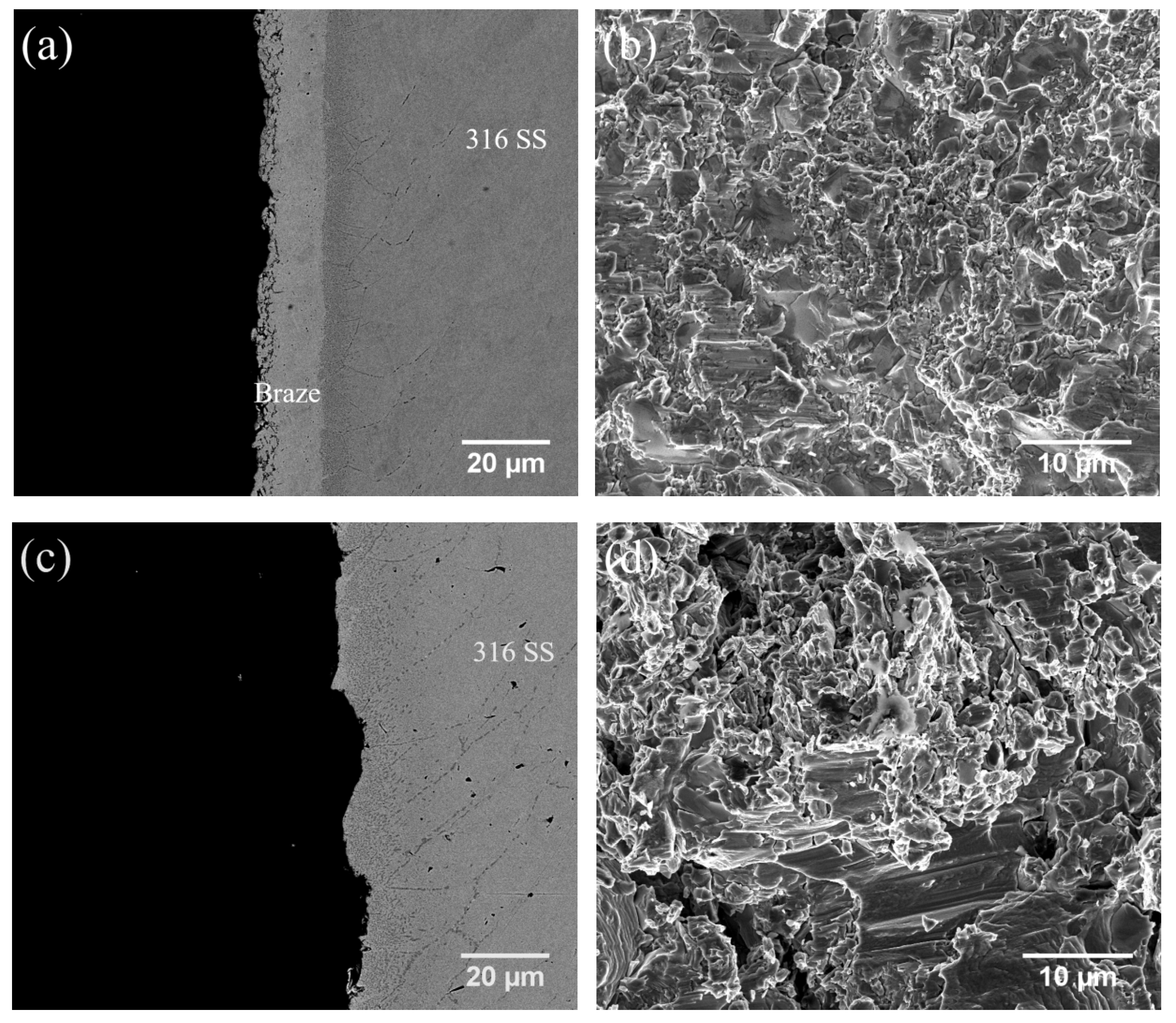
Table 6 shows the average shear strengths of CoCrFeNi/BNi-2/316 SS infrared joints infrared brazed at 1020 °C for 180 and 600 s and at 1050 °C for 600 s, which were 349, 374 and 329 MPa, respectively. The fracture was located in the central CrB of the brazed zone in the specimens brazed at 1020 °C for 180 s, as shown in Figure 6a and Figure 11a. There was no continuous line of CrB in the joint brazed at 1050 °C for 600 s, as displayed in Figure 6c, so the crack was located in the coarsened interfacial boride layer on the 316 SS side, as shown in Figure 11c. Cleavage fractographs are presented in Figure 11b,d.
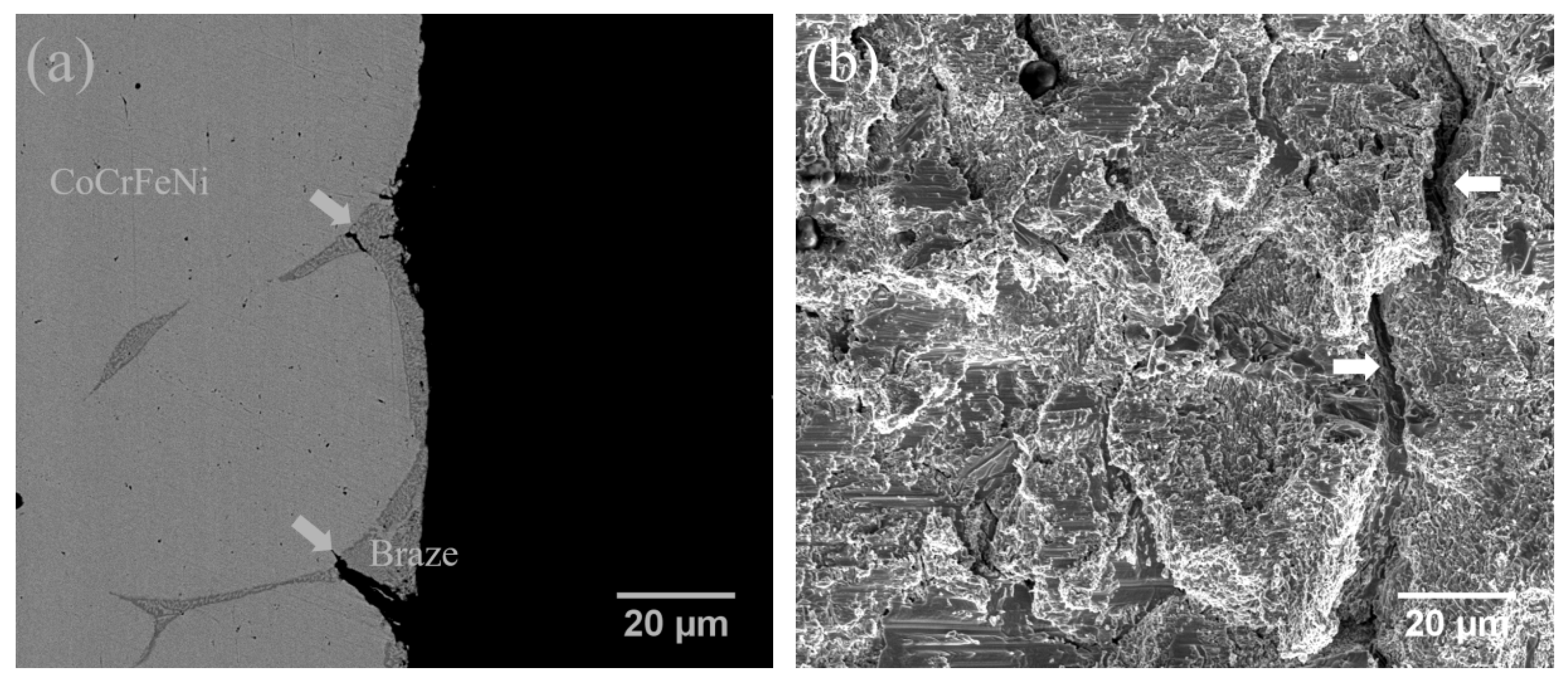
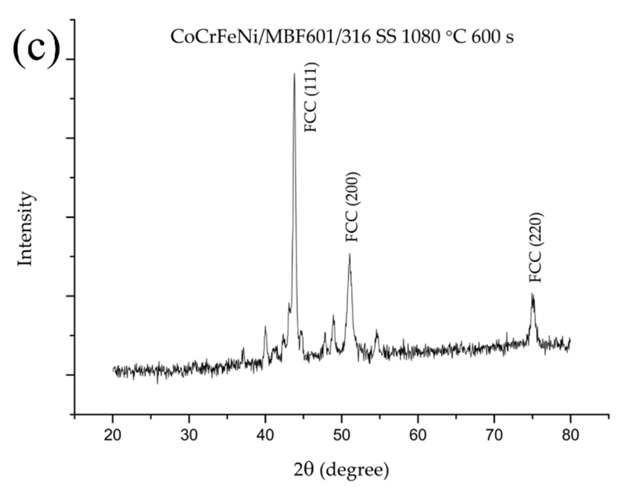
The shear strengths of CoCrFeNi/MBF601/316 SS joints infrared brazed at 1050 °C for 180 and 600 s and at 1080 °C for 600 s were 293, 284 and 324 MPa, respectively. Figure 12 shows the BEI cross-section and SEI fractograph of the CoCrFeNi/MBF601/316 SS joint brazed at 1080 °C for 600 s. All the CoCrFeNi/MBF601/316 joints fractured at the phosphides in the brazed zone. Figure 12a shows the phosphides penetrating into the grain boundaries of the CoCrFeNi substrate and forming cracks, which are marked by arrows. Figure 12b presents the brittle fractograph of the CoCrFeNi substrate after the shear test. Figure 12c shows the XRD analysis of the fractured surface after the shear test. Only the FCC Ni-rich matrix can be identified from its fractograph. There are a few unidentified peaks in Figure 12c because of the existence of phosphides and B /Cr/Fe/P compounds in the joint.
In Table 6, the thickness of the brazed zone increased as the brazing temperature/time for the BNi-2 braze alloy increased. However, for the MBF601 filler, the thickness of the brazed zone decreased as the brazing temperature/time increased. For the BNi-2 filler, the dissolution of central CrB into the substrates resulted in the formation of an interfacial boride layer. There were no interfacial boride layers for the MBF601 filler brazed joint. Central phosphides and B/Co/Cr/Fe/Mn/Ni/P compounds were dissolved into both substrates, and the thickness of the brazed zone decreased.

4. Conclusions

The dissimilar infrared brazing of the CoCrFeMnNi/CoCrFeNi HEA and 316 SS using BNi-2 and MBF601 filler metals was investigated. The target of this study was to optimize the conditions in the dissimilar brazing of HEAs and 316 stainless steel. The wettability, microstructure evolution and shear strength results are summarized below:
1. The wetting angles of BNi-2 and MBF601 fillers at 50 °C above their liquidus temperatures on the CoCrFeMnNi/CoCrFeNi HEA and 316 SS substrates were below 40 degrees. Both fillers showed acceptable wetting ability on the CoCrFeMnNi/CoCrFeNi HEAs and 316 SS for brazing.
2. The CoCrFeMnNi/BNi-2/316 SS joint brazed at 1020 °C was dominated by a Ni-rich matrix with continuous central CrB in the brazed zone. Increasing the brazing temperature caused the central CrB to dissolve into the substrates and form an interfacial boride layer, primarily along the grain boundaries of the substrate. The fracture location was changed from continuous central CrB in the brazed zone into the interfacial boride layer. Similar experimental results were observed in the dissimilar brazing of CoCrFeNi and 316 SS using the BNi-2 filler metal.
3. The CoCrFeMnNi/MBF601/316 SS joint was composed of a CoCrFeMnNi matrix, central phosphides and B/Co/Cr/Fe/Mn/Ni/P compounds, and a few phosphides penetrated into the grain boundaries of the CoCrFeMnNi base metal. When the brazing time and temperature were increased, the central phosphides in the brazed zone almost disappeared and the B/Co/Cr/Fe/Mn/Ni/P compounds became larger. After the shear test, cracks were located at the B/Co/Cr/Fe/Mn/Ni/P compounds and the phosphides penetrating along the grain boundaries of the CoCrFeMnNi base metal.
4. The CoCrFeNi/MBF601/316 SS joint was composed of a (Fe,Ni)-rich matrix and a phosphide eutectic structure with a few B/Cr/Fe/P compounds. Some of the phosphides penetrated into the grain boundaries of the CoCrFeNi and the 316 SS substrates.
5. The CoCrFeNi/316 SS joint had the highest shear strength of 374 MPa when brazed with BNi-2 filler at 1020 °C for 600 s and fractured at the central CrB in the brazed zone. The CoCrFeNi/MBF601/316 SS joint had the highest shear strength of 324 MPa when it was brazed at 1080 °C for 600 s. Cracks were initiated/propagated into the grain boundaries of the CoCrFeNi substrate.

Author Contributions

Conceptualization, R.-K.S. and S.-K.W.; Data curation, C.L. and Y.-S.L.; Formal analysis, C.L. and Y.-S.L.; Funding acquisition, S.-K.W.; Investigation, C.L. and Y.-S.L.; Methodology, R.-K.S. and S.-K.W.; Supervision, S.-K.W.; Writing—original draft, C.L.; Writing—review and editing, R.-K.S. and S.-K.W.

Funding

This research was financially aided by the Ministry of Science and Technology (MOST), Taiwan, under grant numbers MOST 107-2221-E-002-016-MY2 and MOST 107-2218-E-002-019.

Acknowledgments

Appreciation to Professor Hsin-Chih Lin and Mr. Chung-Yuan Kao for EPMA operation in Instrumentation Center, National Taiwan University.

Conflicts of Interest

The authors declare no conflict of interest.

References

  1. Cantor, B.; Chang, I.T.H.; Knight, P.; Vincent, A.J.B. Microstructural development in equiatomic multicomponent alloys. Mater. Sci. Eng. A 2004, 375–377, 213–218. [Google Scholar] [CrossRef]
  2. Hsu, C.Y.; Yeh, J.W.; Chen, S.K.; Shun, T.T. Wear resistance and high-temperature compression strength of FCC CuCoNiCrAl0.5Fe alloy with boron addition. Metall. Mater. Trans. A 2004, 35, 1465–1469. [Google Scholar] [CrossRef]
  3. Yeh, J.W.; Chen, S.K.; Lin, S.J.; Gan, J.Y.; Chin, T.S.; Shun, T.T.; Tsau, C.H.; Chang, S.Y. Nanostructured High-Entropy Alloys with Multiple Principal Elements: Novel Alloy Design Concepts and Outcomes. Adv. Eng. Mater. 2004, 6, 299–303. [Google Scholar] [CrossRef]
  4. Yeh, J.W.; Lin, S.J.; Chin, T.S.; Gan, J.Y.; Chen, S.K.; Shun, T.T.; Tsau, C.H.; Chou, S.Y. Formation of simple crystal structures in Cu-Co-Ni-Cr-Al-Fe-Ti-V alloys with multiprincipal metallic elements. Metall. Mater. Trans. A 2004, 35, 2533–2536. [Google Scholar] [CrossRef]
  5. Yeh, J.W. Recent progress in high-entropy alloys. Ann. Chim. Sci. Mat. 2006, 31, 633–648. [Google Scholar] [CrossRef]
  6. Gao, M.C. Progress in High-Entropy Alloys. JOM 2013, 65, 1749–1750. [Google Scholar] [CrossRef] [Green Version]
  7. Tsai, M.-H. Physical Properties of High Entropy Alloys. Entropy 2013, 15, 5338–5345. [Google Scholar] [CrossRef] [Green Version]
  8. Gao, M.C. Progress in High-Entropy Alloys. JOM 2014, 66, 1964–1965. [Google Scholar] [CrossRef] [Green Version]
  9. Tsai, M.H.; Yeh, J.W. High-Entropy Alloys: A Critical Review. Mater. Res. Lett. 2014, 2, 107–123. [Google Scholar] [CrossRef]
  10. Zhang, Y.; Zuo, T.T.; Tang, Z.; Gao, M.C.; Dahmen, K.A.; Liaw, P.K.; Lu, Z.P. Microstructures and properties of high-entropy alloys. Prog. Mater Sci. 2014, 61, 1–93. [Google Scholar] [CrossRef]
  11. Bhadeshia, H.K.D.H. High entropy alloys. Mater. Sci. Technol. 2015, 31, 1139–1141. [Google Scholar] [CrossRef] [Green Version]
  12. Gao, M.C.; Yeh, J.W.; Liaw, P.K.; Zhang, Y. High-Entropy Alloys: Fundamentals and Applications; Springer International Publishing: New York, NY, USA, 2016. [Google Scholar]
  13. Pickering, E.J.; Jones, N.G. High-entropy alloys: A critical assessment of their founding principles and future prospects. Int. Mater. Rev. 2016, 61, 183–202. [Google Scholar] [CrossRef]
  14. Miracle, D.B.; Senkov, O.N. A critical review of high entropy alloys and related concepts. Acta Mater. 2017, 122, 448–511. [Google Scholar] [CrossRef] [Green Version]
  15. Shi, Y.; Yang, B.; Liaw, P.K. Corrosion-Resistant High-Entropy Alloys: A Review. Metals 2017, 7, 43. [Google Scholar] [CrossRef]
  16. Chen, J.; Zhou, X.; Wang, W.; Liu, B.; Lv, Y.; Yang, W.; Xu, D.; Liu, Y. A review on fundamental of high entropy alloys with promising high–temperature properties. J. Alloys Compd. 2018, 760, 15–30. [Google Scholar] [CrossRef]
  17. Senkov, O.N.; Miracle, D.B.; Chaput, K.J.; Couzinie, J.-P. Development and exploration of refractory high entropy alloys—A review. J. Mater. Res. 2018, 33, 3092–3128. [Google Scholar] [CrossRef]
  18. Murty, B.S.; Yeh, J.W.; Ranganathan, S.; Bhattacharjee, P.P. High-Entropy Alloys; Elsevier Science: Amsterdam, The Netherlands, 2019. [Google Scholar]
  19. Otto, F.; Yang, Y.; Bei, H.; George, E.P. Relative effects of enthalpy and entropy on the phase stability of equiatomic high-entropy alloys. Acta Mater. 2013, 61, 2628–2638. [Google Scholar] [CrossRef] [Green Version]
  20. Gludovatz, B.; Hohenwarter, A.; Catoor, D.; Chang, E.H.; George, E.P.; Ritchie, R.O. A fracture-resistant high-entropy alloy for cryogenic applications. Science 2014, 345, 1153–1158. [Google Scholar] [CrossRef] [Green Version]
  21. Otto, F.; Dlouhý, A.; Somsen, C.; Bei, H.; Eggeler, G.; George, E.P. The influences of temperature and microstructure on the tensile properties of a CoCrFeMnNi high-entropy alloy. Acta Mater. 2013, 61, 5743–5755. [Google Scholar] [CrossRef] [Green Version]
  22. Gludovatz, B.; George, E.P.; Ritchie, R.O. Processing, Microstructure and Mechanical Properties of the CrMnFeCoNi High-Entropy Alloy. JOM 2015, 67, 2262–2270. [Google Scholar] [CrossRef]
  23. Laplanche, G.; Horst, O.; Otto, F.; Eggeler, G.; George, E.P. Microstructural evolution of a CoCrFeMnNi high-entropy alloy after swaging and annealing. J. Alloys Compd. 2015, 647, 548–557. [Google Scholar] [CrossRef]
  24. Wu, Z.; Bei, H.; Otto, F.; Pharr, G.M.; George, E.P. Recovery, recrystallization, grain growth and phase stability of a family of FCC-structured multi-component equiatomic solid solution alloys. Intermetallics 2014, 46, 131–140. [Google Scholar] [CrossRef]
  25. Zhou, W.; Fu, L.M.; Liu, P.; Xu, X.D.; Chen, B.; Zhu, G.Z.; Wang, X.D.; Shan, A.D.; Chen, M.W. Deformation stimulated precipitation of a single-phase CoCrFeMnNi high entropy alloy. Intermetallics 2017, 85, 90–97. [Google Scholar] [CrossRef]
  26. Schuh, B.; Mendez-Martin, F.; Völker, B.; George, E.P.; Clemens, H.; Pippan, R.; Hohenwarter, A. Mechanical properties, microstructure and thermal stability of a nanocrystalline CoCrFeMnNi high-entropy alloy after severe plastic deformation. Acta Mater. 2015, 96, 258–268. [Google Scholar] [CrossRef] [Green Version]
  27. He, J.Y.; Zhu, C.; Zhou, D.Q.; Liu, W.H.; Nieh, T.G.; Lu, Z.P. Steady state flow of the FeCoNiCrMn high entropy alloy at elevated temperatures. Intermetallics 2014, 55, 9–14. [Google Scholar] [CrossRef]
  28. Pickering, E.J.; Muñoz-Moreno, R.; Stone, H.J.; Jones, N.G. Precipitation in the equiatomic high-entropy alloy CrMnFeCoNi. Scr. Mater. 2016, 113, 106–109. [Google Scholar] [CrossRef]
  29. Huang, Y.-C.; Tsao, C.-S.; Wu, S.-K.; Lin, C.; Chen, C.-H. Nano-precipitates in severely deformed and low-temperature aged CoCrFeMnNi high-entropy alloy studied by synchrotron small-angle X-ray scattering. Intermetallics 2019, 105, 146–152. [Google Scholar] [CrossRef]
  30. Otto, F.; Dlouhý, A.; Pradeep, K.G.; Kuběnová, M.; Raabe, D.; Eggeler, G.; George, E.P. Decomposition of the single-phase high-entropy alloy CrMnFeCoNi after prolonged anneals at intermediate temperatures. Acta Mater. 2016, 112, 40–52. [Google Scholar] [CrossRef] [Green Version]
  31. Wu, Z.; Bei, H.; Pharr, G.M.; George, E.P. Temperature dependence of the mechanical properties of equiatomic solid solution alloys with face-centered cubic crystal structures. Acta Mater. 2014, 81, 428–441. [Google Scholar] [CrossRef]
  32. Huo, W.; Zhou, H.; Fang, F.; Hu, X.; Xie, Z.; Jiang, J. Strain-rate effect upon the tensile behavior of CoCrFeNi high-entropy alloys. Mater. Sci. Eng. A 2017, 689, 366–369. [Google Scholar] [CrossRef]
  33. Gali, A.; George, E.P. Tensile properties of high- and medium-entropy alloys. Intermetallics 2013, 39, 74–78. [Google Scholar] [CrossRef] [Green Version]
  34. Huo, W.; Fang, F.; Zhou, H.; Xie, Z.; Shang, J.; Jiang, J. Remarkable strength of CoCrFeNi high-entropy alloy wires at cryogenic and elevated temperatures. Scr. Mater. 2017, 141, 125–128. [Google Scholar] [CrossRef]
  35. Kashaev, N.; Ventzke, V.; Stepanov, N.; Shaysultanov, D.; Sanin, V.; Zherebtsov, S. Laser beam welding of a CoCrFeNiMn-type high entropy alloy produced by self-propagating high-temperature synthesis. Intermetallics 2018, 96, 63–71. [Google Scholar] [CrossRef]
  36. Zhu, Z.G.; Sun, Y.F.; Ng, F.L.; Goh, M.H.; Liaw, P.K.; Fujii, H.; Nguyen, Q.B.; Xu, Y.; Shek, C.H.; Nai, S.M.L.; et al. Friction-stir welding of a ductile high entropy alloy: Microstructural evolution and weld strength. Mater. Sci. Eng. A 2018, 711, 524–532. [Google Scholar] [CrossRef]
  37. Guo, J.; Tang, C.; Rothwell, G.; Li, L.; Wang, Y.-C.; Yang, Q.; Ren, X. Welding of high entropy alloys—A review. Entropy 2019, 21, 431. [Google Scholar] [CrossRef]
  38. Wu, Z.; David, S.A.; Feng, Z.; Bei, H. Weldability of a high entropy CrMnFeCoNi alloy. Scr. Mater. 2016, 124, 81–85. [Google Scholar] [CrossRef] [Green Version]
  39. Wu, Z.; David, S.A.; Leonard, D.N.; Feng, Z.; Bei, H. Microstructures and mechanical properties of a welded CoCrFeMnNi high-entropy alloy. Sci. Technol. Weld. Joining 2018, 23, 585–595. [Google Scholar] [CrossRef]
  40. Jo, M.-G.; Kim, H.-J.; Kang, M.; Madakashira, P.P.; Park, E.S.; Suh, J.-Y.; Kim, D.-I.; Hong, S.-T.; Han, H.N. Microstructure and mechanical properties of friction stir welded and laser welded high entropy alloy CrMnFeCoNi. Met. Mater. Int. 2018, 24, 73–83. [Google Scholar] [CrossRef]
  41. Lin, C.; Shiue, R.K.; Wu, S.K.; Huang, H.L. Infrared brazing Of CoCrFeMnNi equiatomic high entropy alloy using nickel-based braze alloys. Entropy 2019, 21, 283. [Google Scholar] [CrossRef]
  42. Lee, S.J.; Wu, S.K.; Lin, R.Y. Infrared joining of TiAl intermetallics using Ti—15Cu—15Ni foil—I. The microstructure morphologies of joint interfaces. Acta Mater. 1998, 46, 1283–1295. [Google Scholar] [CrossRef]
  43. Shiue, R.K.; Wu, S.K.; Chen, S.Y. Infrared brazing of TiAl intermetallic using BAg-8 braze alloy. Acta Mater. 2003, 51, 1991–2004. [Google Scholar] [CrossRef]
  44. Humpston, G.; Jacobson, D.M. Principles of Soldering and Brazing; ASM International: Materials Park, OH, USA, 1993. [Google Scholar]
  45. Rabinkin, A. Brazing with (NiCoCr)–B–Si amorphous brazing filler metals: Alloys, processing, joint structure, properties, applications. Sci. Technol. Weld. Joining 2004, 9, 181–199. [Google Scholar] [CrossRef]
  46. Vaidya, M.; Trubel, S.; Murty, B.S.; Wilde, G.; Divinski, S.V. Ni tracer diffusion in CoCrFeNi and CoCrFeMnNi high entropy alloys. J. Alloys Compd. 2016, 688, 994–1001. [Google Scholar] [CrossRef]
  47. Shiue, R.K.; Wu, S.K.; Chan, C.H. Infrared brazing Cu and Ti using a 95Ag-5Al braze alloy. Metall. Mater. Trans. A 2004, 35, 3177–3186. [Google Scholar] [CrossRef]
  48. Shiue, R.-K.; Wu, S.K.; Yang, S.-H. Infrared brazing of Ti50Ni50 shape memory alloy and inconel 600 alloy with two ag-cu-ti active braze alloys. Metall. Mater. Trans. A 2017, 48, 735–744. [Google Scholar] [CrossRef]
  49. Okamoto, H.; Schlesinger, M.E.; Mueller, E.M. ASM Handbook. Volume 3, Alloy Phase Diagrams; ASM International: Materials Park, OH, USA, 1992. [Google Scholar]
Figure 1. Illustrations of (a) microstructural observation and (b) shear test specimens.
Crystals 09 00518 g001
Figure 2. The dynamic wetting angles of BNi-2 and MBF601 fillers on the 316 SS.
Crystals 09 00518 g002
Figure 3. Wetting angle measurements of BNi-2 and MBF601 filler alloys on the CoCrFeNi.
Crystals 09 00518 g003
Figure 4. The backscattered electron images (BEIs) of CoCrFeMnNi/BNi-2/316 infrared brazed at (a) 1020 °C for 180 s, (b) 600 s and (c) 1050 °C for 600 s.
Crystals 09 00518 g004
Figure 5. The BEIs of CoCrFeMnNi/MBF601/316 joints infrared brazed at (a) 1050 °C for 180 s, (b) 600 s and (c) 1080 °C for 600 s.
Crystals 09 00518 g005
Figure 6. The BEIs of CoCrFeNi/BNi-2/316 SS joints infrared brazed at (a) 1020 °C for 180 s, (b) 600 s and (c) 1050 °C for 600 s.
Crystals 09 00518 g006
Figure 7. The BEIs of CoCrFeNi/MBF601/316 joints infrared brazed at (a) 1050 °C for 180 s, (b) 600 s and (c) 1080 °C for 600 s.
Crystals 09 00518 g007
Figure 8. The BEI of CoCrFeNi/MBF601/316 joint infrared brazed at 1050 °C for 180 s and the associated elemental mappings determined by EPMA.
Crystals 09 00518 g008
Figure 9. SEM (a) cross-section, (b) fractograph and (c) XRD pattern of CoCrFeMnNi/BNi-2/316 SS joint infrared brazed at 1020 °C for 600 s; (d) cross-section and (e) fractograph of CoCrFeMnNi/BNi-2/316 SS joint infrared brazed at 1050 °C for 600 s.
Crystals 09 00518 g009aCrystals 09 00518 g009b
Figure 10. SEM (a) CoCrFeMnNi side, (b) 316 SS side BEI cross-sections, (c,d) SEI fractographs of CoCrFeMnNi/MBF601/316 SS joint infrared brazed at 1080 °C for 600 s.
Crystals 09 00518 g010
Figure 11. SEM (a) cross-section and (b) fractograph of joint infrared brazed at 1020 °C for 180 s, (c) cross-section and (d) fractograph of CoCrFeNi/BNi-2/316 SS joint infrared brazed at 1050 °C for 600 s.
Crystals 09 00518 g011
Figure 12. SEM (a) cross-section, (b) fractograph and (c) XRD pattern of CoCrFeNi/MBF601/316 SS joint infrared brazed at 1080 °C for 600 s.
Crystals 09 00518 g012aCrystals 09 00518 g012b
Table 1. Brazing conditions in the experiment.
FillerBase MetalTimeTemperature
1020 °C1050 °C1080 °C
BNi-2CoCrFeMnNi/316 SS
CoCrFeNi/316 SS
180 sM/S
600 s M/SM/S
MBF601CoCrFeMnNi/316 SS
CoCrFeNi/316 SS
180 s M/S
600 s M/SM/S
M: Metallographic observation, S: Shear test.
Table 2. The EPMA quantitative chemical analyses in Figure 4.
at.%ABCDD1EF
Co20.416.31.00.50.10.20.2
Cr20.617.28.447.652.414.918.6
Fe19.916.07.32.70.652.368.9
Mn18.713.31.21.00.30.60.9
Ni20.417.173.44.62.410.79.3
B0.019.80.640.344.019.60.0
Mo0.00.00.00.00.10.91.1
Si0.00.38.13.30.10.81.0
phaseCoCrFeMnNiborideNi-richCrBCrBboride316 SS
Table 3. The EPMA quantitative chemical analyses in Figure 5.
at.%GHIJ
Co12.47.313.712.4
Cr21.433.918.521.5
Fe11.211.925.111.2
Mn15.49.714.015.2
Ni17.713.126.717.7
B0.911.70.00.8
Mo0.30.90.20.3
P20.411.20.820.6
Si0.30.31.00.3
phasephosphideB/Co/Cr/Fe/Mn/Ni/P compound CoCrFeMnNi-basedphosphide
Table 4. The EPMA quantitative chemical analyses in Figure 6.
at.%KLMNOP
Co25.623.60.80.50.20.2
Cr25.121.27.947.017.018.7
Fe25.022.67.32.861.069.6
Ni24.323.374.94.79.29.3
B0.09.20.041.510.80.0
Mo0.00.00.00.10.91.1
Si0.00.19.13.40.91.1
phaseCoCrFeNiborideNi-rich CrBboride316 SS
Table 5. The EPMA quantitative chemical analyses in Figure 7.
at.%QRS
Co2.07.10.5
Cr14.629.254.9
Fe39.213.87.8
Ni39.816.61.5
B0.00.221.6
Mo0.11.52.7
P1.131.411.0
Si3.20.20.0
phase(Fe,Ni)-richphosphideB/Cr/Fe/P compound
Table 6. Average shear strengths and thicknesses of the infrared brazed joints.
SubstrateFillerTemperatureTimeAverage Shear StrengthThickness of Brazed Zone
CoCrFeMnNi/316 SSBNi-21020 °C180 s361 ± 27 MPa42 μm
600 s294 ± 20 MPa44 μm
1050 °C600 s328 ± 45 MPa56 μm
MBF6011050 °C180 s216 ± 36 MPa37 μm
600 s276 ± 43 MPa31 μm
1080 °C600 s248 ± 44 MPa30 μm
CoCrFeNi/316 SSBNi-21020 °C180 s349 ± 14 MPa40 μm
600 s374 ± 10 MPa46 μm
1050 °C600 s329 ± 11 MPa60 μm
MBF6011050 °C180 s293 ± 13 MPa15 μm
600 s284 ± 14 MPa11 μm
1080 °C600 s324 ± 6 MPa7 μm