Article

Chiral Optical Tamm States at the Interface between an All-Dielectric Polarization-Preserving Anisotropic Mirror and a Cholesteric Liquid Crystal

1
Kirensky Institute of Physics, Federal Research Center KSC SB RAS, Krasnoyarsk 660036, Russia
2
Siberian Federal University, Krasnoyarsk 660041, Russia
3
Institute of Imaging and Biomedical Photonics, College of Photonics, National Chiao Tung University, Tainan 71150, Taiwan
*
Authors to whom correspondence should be addressed.
Crystals 2019, 9(10), 502; https://doi.org/10.3390/cryst9100502
Submission received: 30 August 2019 / Revised: 23 September 2019 / Accepted: 24 September 2019 / Published: 26 September 2019
(This article belongs to the Special Issue Localized Optical Modes in Liquid Crystals)

Abstract

:
As a new localized state of light, the chiral optical Tamm state exists at the interface between a polarization-retaining anisotropic mirror and a substance with optical activity. Considering a hybrid structure comprising a metal-free polarization-preserving mirror and a cholesteric liquid crystal, we highlight the high Q factor arising from the all-dielectric framework. The intensity of localized light decreases exponentially with increasing distance from the interface. The penetration of the field into the cholesteric liquid crystal is essentially prohibited for wavelengths lying in the photonic bandgap and close to the cholesteric pitch length. The dielectric mirror has its own photonic bandgap. The energy transfer along the interface can be effectively switched off by setting the tangential wave vector to zero. The spectral behavior of the chiral optical Tamm state is observed both as reflection and transmission resonance. This Fano resonance is analogous to the Kopp–Genack effect. Our analytics are well in line with precise calculations, which may pave a new route for the future development of intelligent design for laser and sensing applications.

1. Introduction

The electromagnetic analog of the Tamm state of electrons on the superlattice interface is referred to as the optical Tamm state (OTS) [1]. The optical Tamm state is also called the Tamm plasmon polariton if excited at the interface of the superlattice and a metal. In this case, the radiation field is coupled with the surface plasmon excitation [2,3]. In OTS, light is localized at the common interface of two media where multiple re-reflections occur and light turns out to be blocked between two media playing the role of mirrors. The OTS manifests itself in experiments as a narrow resonance in the transmittance or reflectance spectrum of the sample. Such a state can be excited perpendicular to the surface. In this case, OTS is a localized surface state impeding energy transfer along the interface, leading to the light intensity to exponentially decrease with the increasing distance from the interface in both (the transmitting and reflecting) directions. OTSs have found application in various optical devices with new ways to control light. Modern technologies offer a great number of structures which allow obtaining OTSs using various optical materials and metamaterials including chiral, nonlinear, resonant, nanocomposite, and anisotropic ones [4,5,6,7]. Theoretically and experimentally investigated directional surface waves, called Dyakonov surface waves, are supported at the interface of dielectric uniaxial birefringent media based on a modified Otto–Kretchmann configuration [8,9].
Chiral media, unlike achiral ones, have no mirror symmetry of optical properties. One of the vivid examples of a chiral medium is a cholesteric liquid crystal (CLC), which consists of oriented molecules of which the predominant direction is coiled in space like a helix. CLCs have a continuous helical symmetry of the dielectric permittivity tensor and, due to the periodicity, are one-dimensional photonic crystals [10,11]. Of great interest is selective light reflection from CLCs since the reflected wave retains circular polarization of the same sign as that of the handedness of the CLC and since the orthogonal component with circular polarization of the opposite sign is hardly reflected from the liquid crystal. Localized states were obtained at the interface of two CLC media [12]. The difficulty in OTS excitation on the interface of chiral and achiral mirrors results from the fact that the isotropic mirror changes the polarization of light and that the diffracting wave in the chiral photonic crystal is transformed into the non-diffracting wave and after another re-reflection leaves the interface [13]. Another anisotropic layer can compensate polarization changes. This layer transforms the polarization of the reflected light into the diffracting one; in the simplest case, this layer can be represented by a quarter-wave plate [14,15] or planar anisotropic defect in CLC [16]. In the case of CLC surrounded by two mirrors, a Fabry–Pérot resonator is formed and the compensation of the polarization change is not required [17]. In Reference [18], another method to hinder the polarization change in the case of reflection from the interface was suggested. This can be achieved by adding an anisotropic substrate to the chiral medium. A case of light incident normal to the interface was considered analytically. However, the solution obtained in this case imposes a strong condition on the parameters of the uniform substrate which, upon reflection, must retain the properties of the incident wave. Thus, the unusual polarization of the reflected light is due to anisotropic materials.
The mirror which does not change the sign of the polarization of the reflected light is referred to as a polarization-preserving anisotropic mirror (PPAM) [19]. The field reflected from the interface of this mirror has the same polarization as the incident field. For example, the light of the right circular polarization upon reflection also retains the right circular polarization. Generally, to create PPAM, it is necessary to combine the properties of the electric and magnetic mirrors [20,21,22]. The electric mirror is an isotropic ideal metal mirror which, upon reflection of light, influences the electric component of the electromagnetic wave. The phase of the electric component changes by 180 , and a node of a standing wave is formed at the reflecting interface. The magnetic mirror, on the contrary, reflects light by reversing its magnetic vector. PPAM can be in the form of a flat interface of a metallo-dielectric nanocomposite consisting of spherical nanoparticles of silver dispersed in a transparent template. Such a mirror transfers about 80% of the energy of an incident wave into a reflected wave with the same polarization in a particular spectral range [23]. A multilayered PPAM structure consisting of alternating similar uniaxial dielectric layers with orthogonal directions of the optical axes is called a Reusch pile [24,25]. By choosing the appropriate parameters, it is possible to optimize the spectral range of reflection of the Reusch pile. It is analytically shown that, with decreasing thickness of the first layer, the frequency range broadens, in which the phase of the reflected light does not change and the reflectance approaches 100% [19]. The PPAM properties can also be observed in acousto-optical cells [26] as well as in chiral thin structured films [27].
The localized state of light which appears at the interface between a PPAM and an optically chiral medium such as CLC is referred to as the chiral optical Tamm state (COTS) [18]. In this state, light is localized near the interface between two media and the field exponentially decreases with increasing distance from the interface. The penetration of the field from the PPAM into the chiral medium is almost hindered for the wavelengths corresponding to the photonic bandgap (PBG) and the wavelengths close to the pitch of the CLC. Since the anisotropic mirror retaining polarization has another photonic bandgap, the energy transfer along the interface of the media can effectively be stopped when the tangential wave vector vanishes. The spectral manifestation of COTS can be observed both upon reflection and transmission. A detailed description of the possibility of procuring such a state in the presence of an ideal PPAM and a non-absorbing layer of cholesteric having finite anisotropy is given in Reference [28]. For an accurate and detailed description of COTS, various methods should be used. By analytical formulas for the reflection amplitude of PPAM [19,29] and CLC [30], it is possible to determine the localization of the appearing resonance transmission peaks at the interface of two media. The spectral properties of the state depends upon the angle between the optical axes of the media at the interface. However, for acquiring the maximal transmission coefficient in resonance peaks, i.e., for creating the optimum critical coupling, it is worth using the temporal coupled-mode theory [31]. The temporal coupled-mode theory is successfully used for studying OTS [32,33]. Within this theory, the light field is decomposed into a superposition of several simple solutions connected with each other by energy fluxes. By restricting oneself to several fundamental modes and, then, by writing down the differential equations for their amplitudes, one can explain the stability of the states and can choose the necessary spectral characteristics. The resonance is described using the coupling coefficients, which are determined by geometrical and physical peculiarities of the structure. In Reference [28], it is shown that COTS can be considered strictly localized only when the anisotropies in the magnetic permeability and electric permittivities are equal in their values and the axes of the corresponding tensors coincide; otherwise, COTS is manifested in the form of the resonances of polarized reflection with two relaxation constants determined by the differences in permittivity and in thickness of the cholesteric layer.
In order to obtain COTS with effective resonance control, a multilayered PPAM is used in this study. Here, emphasis is placed on the advantages of the fully dielectric structure in achieving a high Q factor. In the framework of the coupled-mode theory, consideration is given to the conditions of critical coupling, taking into account the energy leakage caused by the physical and geometrical parameters of the structure. The obtained analytical expressions are in good agreement with the numerical calculations obtained using the Berreman matrix method [34,35]. The OTS can be further used for intelligent design for laser [36,37] and sensing applications [38].

2. Description of the Model

The optical Tamm state is excited at the interface between the dielectric PPAM and a CLC (Figure 1). The multilayered PPAM is a structure composed of alternating identical uniaxial dielectric layers with different refractive indices n e p = ε e p and n o p = ε o p . Let us describe it by different dielectric tensors of two neighboring layers: vertical ε ^ V and horizontal ε ^ H . The number of V–H pairs (unit cells of the structure) is equal to N p , and the period of the structure is equal to Λ p = 2 a , where a is the thickness of each dielectric layer.
CLC is an optical chiral medium having continuous helical symmetry of the dielectric permittivity tensor. For the mesophase, the following characteristics are introduced: the value of the helix pitch is 2 Λ c = 1 μ m; L is the thickness of the cholesteric layer; N c is the number of periods; and the refractive indices of the extraordinary and ordinary beams n c = n e c = ε c and n c = n o c = ε c are close to the values of n e p and n o p of PPAM, respectively.

3. Eigenmode Phase Matching Condition

Let us define the conditions of eigenmode phase matching under which the field is localized at the boundary of the hybrid structure PPAM–CLC. This condition gives the spectral position of the OTS. PPAM is a periodically layered medium, a Bragg reflector; thus, it can be described using analytical formulas [29]. The expression for the amplitude reflection coefficient is as follows:
r N p = C U N - 1 A U N - 1 - U N - 2 = C A - sin N - 1 K Λ p / sin N K Λ p ,
arg r N p = χ p ,
where U N = sin N + 1 K Λ p / sin K Λ p and K = 1 / Λ p arccos ( A + D ) / 2 is the Bloch wavenumber. The elements of the transformation matrix for a cell showing the relation between the amplitudes of the plane waves in the first layer and the respective amplitudes in the neighboring unit cell are as follows:
A = e i k 1 z a cos k 2 z a + 1 2 i q + 1 q sin k 2 z a ; C = e i k 1 z a - 1 2 i q - 1 q sin k 2 z a ; D = e - i k 1 z a cos k 2 z a - 1 2 i q + 1 q sin k 2 z a .
Here, k 1 z = ω / c n e p and k 2 z = ω / c n o p are the wave vectors for the first and second media, respectively; q = k 2 z / k 1 z = ε o p / ε e p is geometric progression denominator; ε ¯ p = ε o p + ε e p / 2 is the arithmetic mean over ordinary and extraordinary permittivities for PPAM; and the Bloch wavenumber is given by the expression cos K Λ p = Re A .
Let us write the reflection coefficient for the cholesteric in the following form [10]:
r L c = i δ sin β L β τ 0 / κ 2 cos β L + i τ 0 / 2 κ 2 + β / κ 2 - 1 sin β L ,
arg r L c = χ c .
Here, β = κ 1 + τ 0 / 2 κ 2 - τ 0 / κ 2 + δ 2 1 / 2 1 / 2 , κ = ω ε ¯ c / c , τ 0 = 4 π / Λ c , ε ¯ c = ε o c + ε e c / 2 is the arithmetic mean over ordinary and extraordinary permittivities for CLC; and δ = ( ε e c - ε o c ) / ( ε e c + ε o c ) is anisotropy.
The equation for the phase 2 χ c of a wave reflected from CLC for a semi-infinite CLC can be written in the following form [28]:
cos 2 χ c = λ - λ g c Δ λ ,
where λ g c = Λ c ( n e c + n o c ) is the wavelength in the center of the CLC bandgap and Δ λ = λ g c ( n e c - n o c ) / ( n e c + n o c ) is the half-width of the CLC bandgap.
Using the same terms for PPAM, one can approximately write down an equation for the phase 2 χ p of a wave reflected from PPAM:
sin 2 χ p - ω - ω g p Δ ω = ω Λ p π c - 1 ω Λ p π c - 1 π 2 1 - q 1 + q π 2 1 - q 1 + q ,
where ω g p = π c π c Λ p Λ p is the frequency in the center of the PPAM bandgap and Δ ω is the half-width of the PPAM bandgap.
Let us write down the expression for the localization of the field at the interface of the PPAM–CLC structure using Equations (6) and (7) and take into account the conditions of eigenmode phase matching at the interface:
π m = χ p + χ c + φ .
Here, m is an arbitrary integer and φ is the angle between the optical axes of PPAM and CLC at the interface. During a cycle of two re-reflections, there appears the geometric component of the phase equal to 2 φ along with the dynamic phase. The dynamic phase grows with optical distance. Therefore, the phase variation by φ angle is not a dynamic phase, as it does not change the optical distance. Such a phase shift is called the geometric phase [39,40].

4. Temporal Coupled-Mode Theory

Optical properties of the localized state such as COTS can be described using the temporal coupled-mode theory. The theory declares that any localized state (resonance) can be described by an eigenmode frequency ω 0 and the number of ports N l for the energy to be transferred into this state and to leak out of it. Here, the energy loss in three channels (to be detailed later) is described by the relaxation times τ l , l = 1 , 2 , 3 . We assume the state to be described by the complex amplitude A and energy | A | 2 . The state can be presented as the sum of all the incoming and outgoing energy fluxes with the amplitudes s l ± . If the energy outcome from the state is made through three energy channels with the relaxation times τ 1 , τ 2 , and τ 3 , then the state relaxation time is defined as 1 / τ = 1 / τ 1 + 1 / τ 2 + 1 / τ 3 . The change in the amplitude A satisfies the following equation:
d A / d t = - i ω 0 A - A / τ ,
which has the following solution: A ( t ) = A ( 0 ) e - i ω 0 t - t / τ .
Considering the incoming and outgoing energy fluxes s l ± , one can rewrite Equation (9) as follows:
d A / d t = - i ω 0 A - l = 1 3 A / τ l + κ 1 s 1 + + κ 2 s 2 + + κ 3 s 3 + ,
s l - = s l + + κ l A .
Here, κ l is the value characterizing the coefficient of channel coupling. It is sufficient to know the relaxation times τ l and resonance frequency ω 0 because κ l = 2 / τ l . Finally, the change in the field amplitude of the localized state can be written as follows:
d A d t = - i ω 0 A - i = 1 3 A / τ l + i = 1 3 2 τ l s l + ,
and the relationship of the flux amplitudes is determined by the following expression:
s l - = - s l + + 2 τ l A .
With Equations (12) and (13), one can predict the transmission spectrum of the hybrid structure. In the general case, the transmission coefficient is the ratio of the amplitudes of incident and transmitted waves. The incident radiation with the frequency ω oscillates according to the harmonic form e - i ω t , making d A / d t = - i ω A . Under these conditions, Equations (12) and (13) with s 2 + = s 3 + = 0 lead to the following:
- i ω A = - i ω 0 A - i = 1 3 A / τ l + i = 1 3 2 τ l s l + , s 1 - = - s 1 + + 2 τ 1 A , s 2 - = 2 τ 2 A , s 3 - = 2 τ 3 A .
The reflectance defined as the fraction of the incident light energy that is reflected can be written in the following form:
R ( ω ) = s 1 - 2 s 1 + 2 = ( ω - ω 0 ) 2 + 1 / τ 1 - 1 / τ 2 - 1 / τ 3 2 ( ω - ω 0 ) 2 + 1 / τ 1 + 1 / τ 2 + 1 / τ 3 2 .
Similarly, one can obtain the following expressions for the transmission coefficients of the system:
T 1 2 ( ω ) = s 2 - 2 s 1 + 2 = ( 2 / τ 2 ) | A | 2 | s 1 + | 2 = 4 / ( τ 1 τ 2 ) ( ω - ω 0 ) 2 + 1 / τ 1 + 1 / τ 2 + 1 / τ 3 2 ,
T 1 3 ( ω ) = s 3 - 2 s 1 + 2 = ( 2 / τ 3 ) | A | 2 | s 1 + | 2 = 4 / ( τ 1 τ 3 ) ( ω - ω 0 ) 2 + 1 / τ 1 + 1 / τ 2 + 1 / τ 3 2 .
From Equation (15), it is clear that zero reflection and, thus, 100% transmission from channel 1 to channels 2 and 3 are achieved at ω = ω 0 and 1 / τ 1 = 1 / τ 2 + 1 / τ 3 . This condition is referred to as the condition of critical (optimal) coupling.
At finite thicknesses of PPAM and cholesteric, the energy from COTS can leak out through three channels. The first channel with the relaxation time τ p is associated with PPAM transmission. The second channel with τ ψ is associated with polarization losses at the PPAM–CLC interface. The third channel with τ c is associated with the transmission of the cholesteric layer. In the general case, the relaxation time is defined as the ratio of the stored energy E to the leakage power P, taken with the positive sign:
τ 2 = E P = Energy   stored Power   of   leakage .
Here, τ is the amplitude relaxation time, which is twice as long as the energy relaxation time. The energy E can be determined by integrating its density W = [ E D + H B ] / 8 π over the space in Gaussian units. For a traveling wave, period-averaged densities of electric and magnetic energy components are equal since E D ¯ = H B ¯ . Here, | E 2 | ¯ = | E 0 2 | / 2 , where E 0 is the wave amplitude. As a result, the energy density in PPAM is defined as W ¯ = ε ¯ p | E 0 2 | / 8 π , while in the bulk cholesteric, it is defined as W ¯ = ε ¯ c | E 0 2 | / 8 π . A standing wave at the interface is formed by two waves of the same amplitude traveling in opposite directions. For simplicity, one can assume ε ¯ p = ε ¯ c = ε ¯ and W ¯ 0 = ε ¯ | E 0 2 | / 8 π . Integration should be performed over both the volumes of PPAM and cholesteric. The total energy is determined as E = E p + E c . As a result of integration, one obtains the following:
E = m = 0 N p W ¯ 0 a q m + 0 L W ¯ 0 exp ( - 2 | n f | · 2 π z / λ 0 ) d z = W ¯ 0 L ,
L = a 1 - q N p + 1 1 - q + λ 0 4 π | n f | ( 1 - e - 4 π | n f | L λ 0 ) .
Here, λ 0 = ( ε e c + ε o c ) / 2 + [ ( ε e c - ε o c ) / 2 ] cos 2 χ ¯ c , χ ¯ c = ( χ E + χ H ) / 2 ( χ E and χ H are the angles between the CLC director and vectors of electric and magnetic fields), | n f | = sin 2 χ c ¯ · ( n e c - n o c ) / ( n e c + n o c ) is the fast wave refractive index, and L is effective length of the cavity spreading inside the distributed mirrors.
The leakage powers P ψ , P p , and P c are proportional to the energy velocity c / ε ¯ and energy densities W ¯ ψ , W ¯ p , and W ¯ c respectively. The energies E ψ , E p , E c can be defined as follows:
E ψ = E 0 sin ( ψ / 2 ) , E p = 2 E 0 q N p , E c = 2 E 0 e - 2 π | n f | L λ 0 ,
where ψ = χ E - χ H .
Equation (18) for the stored energy and leakage power in each channel yields the corresponding rates of the energy relaxation. In the middle of bandgaps ω = ω g c = ω g p , the equations can be simplified as follows:
τ p = ε ¯ ε o p q - 2 N 2 ε ¯ L c , τ ψ = sin - 2 ( ψ / 2 ) 2 ε ¯ L c , τ c = e 4 π | n f | L λ 0 2 ε ¯ L c .
The value of τ ψ becomes larger in account of PPAM polarization leakage [19]. The expressions obtained allow for the determination of the times of the energy leakage from COTS into each channel. Here, the spectral line-width corresponding to COTS is defined by the total rate of the energy leakage from the localized state as follows:
1 τ = 1 τ p + 1 τ ψ + 1 τ c .
This is sufficient to describe the spectral manifestation of the state using the temporal coupled-mode theory.
The system design details given in Section 2 are used in relaxation time expressions of Equation (22) to describe spectral coefficients in Equations (15)–(17).

5. Results and Discussion

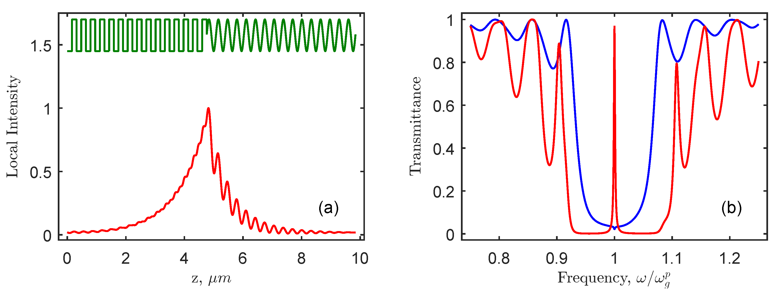
Figure 2a depicts the effective reflective index in the structure comprising PPAM and CLC, depending on the depth z of the layered structure as well as on the normalized local intensity | E | 2 for COTS. One can see in the figure that light is localized near the interface CLC–PPAM and that the local intensity of the field falls exponentially with the increasing distance from this interface. Figure 2b presents the transmission spectra for two opposite circular polarizations. When the polarization sign of the propagating wave is coincident with the sign of the cholesteric helix, the transmission has a resonance peak in the center of the bandgap. For the polarization of the opposite sign, a small Fano dip is observed at the resonant frequency.
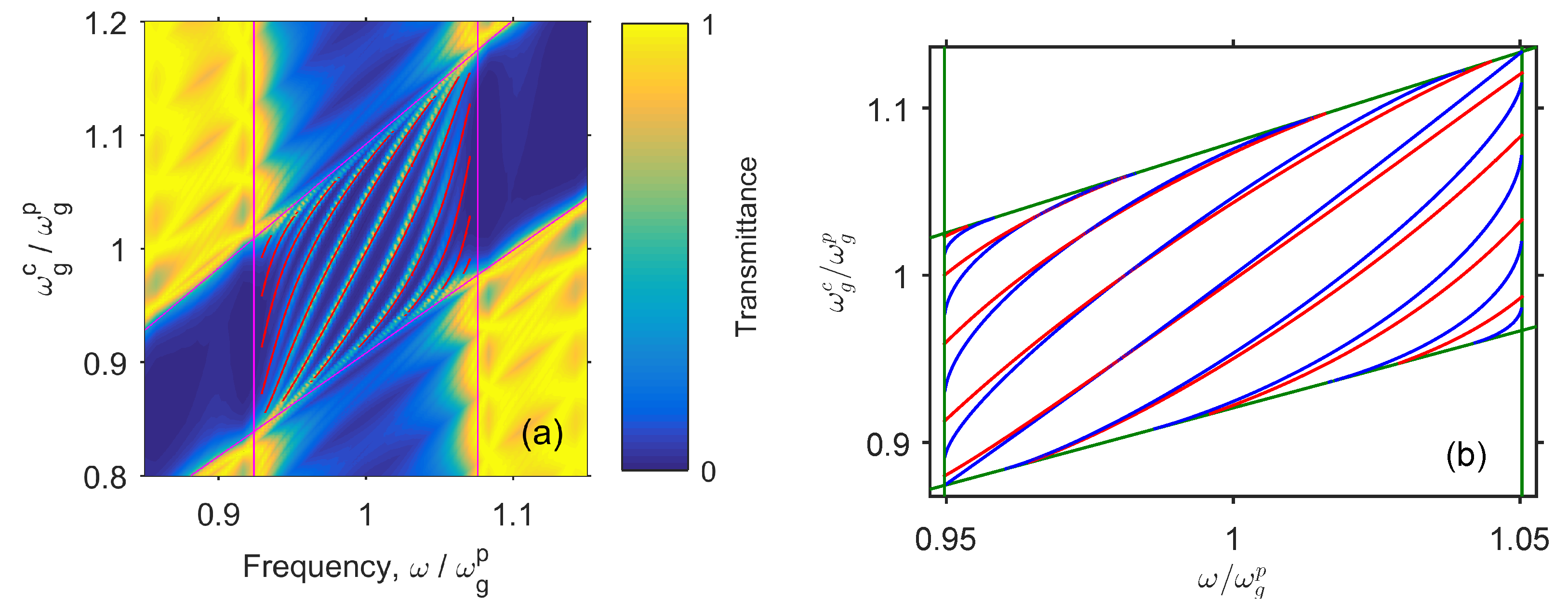
Figure 3a shows the transmission spectra of the structure calculated using the Berreman method for different positions of the PPAM and CLC bandgaps at the normalized frequencies. With the anisotropies being equal, the bandgap for CLC is wider than for PPAM; this advantage of the CLC mirror is compensated by its reflection of a single circular polarization. It is seen that, in the frequency range where the CLC and PPAM bandgaps fully or partially overlap, a resonant transmission peak appears. Its position qualitatively agrees with the calculation using Equation (8). The quantitative difference from the accurate calculation is noticable in the vicinity of the angle φ = - π / 4 , where the theory predicts the COTS transition to the edge mode, the offset of the resonance peak to the bandgap edge, and the appearance of a peak at the opposite edge of the bandgap. At fixed φ = - π / 4 , the peak is observed both at the short wavelength edge of the bandgap at ω g c / ω g p > 1 and at the long wavelength edge of the bandgap at ω g c / ω g p < 1 . Figure 3b presents the corresponding dispersion curves of COTS. The solutions of Equations (1)–(5) for finite media depicted by the red color are close to the solutions of Equations (6) and (7) for semi-infinite media depicted by the blue color. The approximate Equation (7) gives an apparent difference in solutions. This difference becomes negligible when N p , N c and when the normalized anisotropy approaches zero δ / ε ¯ 0 .
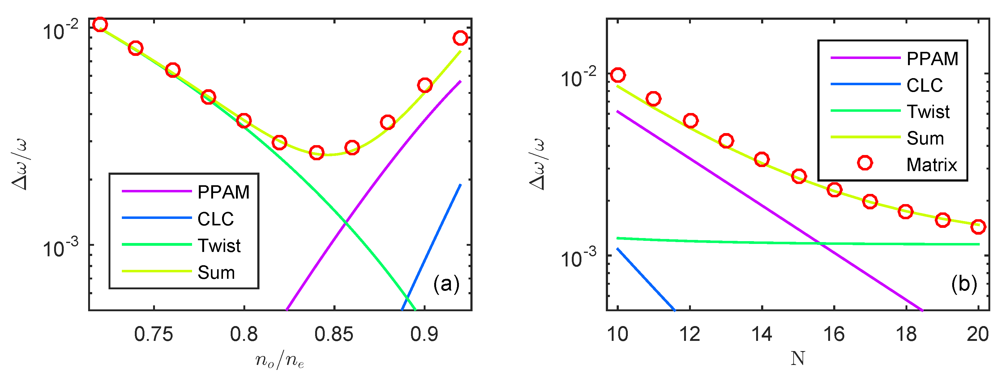
In Figure 4, the COTS decay rate is characterized by the dimensionless spectral line-width Δ ω / ω = 4 / ω τ . The decay rate varies non-monotonously with the contrast n o / n e and monotonously with the number of periods N = N p = N c for both PPAM and CLC. Curves are obtained by means of the coupled-mode theory, and the circles correspond to straightforward calculations of spectral line-width obtained by the Berreman transfer matrix method [34]. The quality factor Q = ω / Δ ω varies in the interval 100 < Q < 700 for the periods 10 N 20 . In logarithmic scale, the lines are almost straight for exponential dependencies. The CLC relaxation is negligible compared to the PPAM relaxation and twist relaxation. The PPAM and twist line intersections show the critical coupling condition with minimal decay rate in Figure 4a and maximal curvature in Figure 4b.
It has to be indicated that COTS can be treated as a bound state in the continuum [41,42]. The signature of that in Figure 2b is the Fano resonance for circular polarization opposite the handedness of the cholesteric. The eigenfrequency lies in the bandgap of diffractive polarized modes, ensuring that the state is bound. At the same time. the eigenfrequency is embedded into the conducting band of non-diffractive modes, meaning the continuum. To turn the quasi-bound state in the continuum into ideal bound state, one has to remove the coupling by setting ψ = 0 , τ ψ = 0 . Realizing this state experimentally is a challenge as it requires materials with strong magnetic anisotropy to ensure strictly zero coupling [43,44]. This bound-state analogy is obviously valid for any localized state in CLC, for example, a defect mode and state at the phase jump boundary (the twist defect) [12,45,46]. It is highly anticipated that a nonzero tangential wave vector brings about moving along the interface as it was shown for cholesterics [47] and that chirality of the described state brings about nontrivial topology [48].
In conclusion, the chiral optical Tamm state at the interface of a layered structure and a cholesteric liquid crystal is investigated, the former being characterized by alternating equal uniaxial dielectric layers with orthogonal optical axes. It is shown that the state obtained possesses high-quality factors and can effectively be frequency tuned.

Author Contributions

N.V.R.—methodology, visualization, and writing—original draft; I.V.T.—conceptualization, methodology, software, validation, and writing—review and editing; S.Y.V.—conceptualization, validation, and supervision; R.G.B. and M.V.P.—methodology and visualization; and W.L.—conceptualization, validation, supervision, and writing—review and editing.

Funding

Russian Foundation for Basic Research (RFBR), Russia, grant No. 19-52-52006; Ministry of Science and Technology, Taiwan (MOST), grant No. 106-2923-M-009-002-MY3; M.V.P. thanks RFBR and KRSTSF for the research Project No. 18-42-243025.

Acknowledgments

The authors are thankful to Pavel S. Pankin for valuable discussions and comments.

Conflicts of Interest

The authors declare no conflict of interest.

Abbreviations

The following abbreviations are used in this manuscript:
OTSOptical Tamm State
CLCCholesteric Liquid Crystal
PPAMPolarization-Preserving Anisotropic Mirror
COTSChiral Optical Tamm State

References

  1. Kavokin, A.V.; Shelykh, I.A.; Malpuech, G. Lossless interface modes at the boundary between two periodic dielectric structures. Phys. Rev. B 2005, 72, 1–4. [Google Scholar] [CrossRef]
  2. Kaliteevski, M.A.; Iorsh, I.; Brand, S.; Abram, R.A.; Chamberlain, J.M.; Kavokin, A.V.; Shelykh, I.A. Tamm plasmon-polaritons: Possible electromagnetic states at the interface of a metal and a dielectric Bragg mirror. Phys. Rev. B 2007, 76, 165415. [Google Scholar] [CrossRef] [Green Version]
  3. Vinogradov, A.P.; Dorofeenko, A.V.; Merzlikin, A.M.; Lisyansky, A.A. Surface states in photonic crystals. Usp. Fiz. Nauk 2010, 180, 249–263. [Google Scholar] [CrossRef]
  4. Capaldo, P.; Mezzadrelli, A.; Pozzato, A.; Ruffato, G.; Massari, M.; Romanato, F. Nano-fabrication and characterization of silicon meta-surfaces provided with Pancharatnam-Berry effect. Opt. Mater. Express 2019, 9, 1015–1032. [Google Scholar] [CrossRef]
  5. Afinogenov, B.I.; Bessonov, V.O.; Soboleva, I.V.; Fedyanin, A.A. Ultrafast all-optical light control with Tamm plasmons in photonic nanostructures. ACS Photonics 2019, 6, 844–850. [Google Scholar] [CrossRef]
  6. Fedorin, I. Surface electromagnetic waves at the interface between dissipative porous nanocomposite and hypercrystal under different temperatures. Phys. Lett. A 2019, 125863. [Google Scholar] [CrossRef]
  7. Takayama, O.; Bogdanov, A.; Lavrinenko, A. Photonic surface waves on metamaterial interfaces. J. Phys. Condens. Matter 2017, 29, 463001. [Google Scholar] [CrossRef] [PubMed]
  8. Takayama, O.; Crasovan, L.C.; Johansen, S.K.; Mihalache, D.; Artigas, D.; Torner, L. Dyakonov surface waves: A review. Electromagnetics 2008, 28, 126–145. [Google Scholar] [CrossRef]
  9. Takayama, O.; Crasovan, L.; Artigas, D.; Torner, L. Observation of Dyakonov Surface Waves. Phys. Rev. Lett. 2009, 102, 043903. [Google Scholar] [CrossRef]
  10. Belyakov, V.A.; Sonin, A.S. Optika Kholestericheskikh Zhidkikh Kristallov [Optics of Choltsteric Liquid Crystals]; Nauka Publ.: Moscow, Russia, 1982; p. 360. [Google Scholar]
  11. Belyakov, V.A. Diffraction Optics of Complex-Structured Periodic Media: Localized Optical Modes of Spiral Media; Springer International Publishing: Cham, Switzerland, 2019; p. 253. [Google Scholar] [CrossRef]
  12. Schmidtke, J.; Stille, W. Photonic defect modes in cholesteric liquid crystal films. Eur. Phys. J. E Soft Matter 2003, 12, 553–564. [Google Scholar] [CrossRef]
  13. Timofeev, I.V.; Arkhipkin, V.; Vetrov, S.; Zyryanov, V.; Lee, W. Enhanced light absorption with a cholesteric liquid crystal layer. Opt. Mater. Express 2013, 3. [Google Scholar] [CrossRef]
  14. Vetrov, S.Y.; Pyatnov, M.V.; Timofeev, I.V. Surface modes in “photonic cholesteric liquid crystal–phase plate–metal” structure. Opt. Lett. 2014, 39, 2743–2746. [Google Scholar] [CrossRef] [PubMed]
  15. Vetrov, S.Y.; Pyatnov, M.; Timofeev, I.V. Spectral and polarization properties of a ’cholesteric liquid crystal–Phase plate–Metal’ structure. J. Opt. 2015, 18. [Google Scholar] [CrossRef]
  16. Pyatnov, M.; Vetrov, S.Y.; Timofeev, I.V. Localized optical modes in a defect-containing liquid-crystal structure adjacent to the metal. J. Opt. Soc. Am. B Opt. Phys. 2017, 34. [Google Scholar] [CrossRef]
  17. Isaacs, S.; Placido, F.; Abdulhalim, I. Investigation of liquid crystal Fabry–Pérot tunable filters: Design, fabrication, and polarization independence. Appl. Opt. 2014, 53, H91. [Google Scholar] [CrossRef] [PubMed]
  18. Timofeev, I.V.; Vetrov, S.Y. Chiral optical Tamm states at the boundary of the medium with helical symmetry of the dielectric tensor. JETP Lett. 2016, 104, 380–383. [Google Scholar] [CrossRef] [Green Version]
  19. Rudakova, N.V.; Timofeev, I.V.; Vetrov, S.Y.; Lee, W. All-Dielectric polarization-preserving anisotropic mirror. OSA Contin. 2018, 1, 682. [Google Scholar] [CrossRef]
  20. Plum, E.; Zheludev, N.I. Chiral mirrors. Appl. Phys. Lett. 2015, 106, 221901. [Google Scholar] [CrossRef] [Green Version]
  21. Rajasekharan, R.; Roberts, A. Optical ’magnetic mirror’ metasurfaces using interference between Fabry–Pérot cavity resonances in coaxial apertures. Sci. Rep. 2015, 5, 10297. [Google Scholar] [CrossRef]
  22. Fedotov, V.A.; Rogacheva, A.V.; Zheludev, N.I.; Mladyonov, P.L.; Prosvirnin, S.L. Mirror that does not change the phase of reflected waves. Appl. Phys. Lett. 2006, 88, 091119. [Google Scholar] [CrossRef] [Green Version]
  23. Rudakova, N.V.; Timofeev, I.V.; Pankin, P.S.; Vetrov, S.Y. Polarization-preserving anisotropic mirror on the basis of metal–dielectric nanocomposite. Bull. Russ. Acad. Sci. Phys. 2017, 81, 10–14. [Google Scholar] [CrossRef]
  24. Reusch, E. Untersuchung über Glimmercombinationen. Ann. Phys. Chem. 1869, 214, 628–638. [Google Scholar] [CrossRef]
  25. Dixit, M.; Lakhtakia, A. Selection strategy for circular-polarization-sensitive rejection characteristics of electro-optic ambichiral Reusch piles. Opt. Commun. 2008, 281, 4812–4823. [Google Scholar] [CrossRef]
  26. Voloshinov, V.B.; Porokhovnichenko, D.L.; Dyakonov, E.A. Design of far-infrared acousto-optic tunable filter based on backward collinear interaction. Ultrasonics 2018, 88, 207–212. [Google Scholar] [CrossRef] [PubMed]
  27. Faryad, M.; Lakhtakia, A. The circular Bragg phenomenon. Adv. Opt. Photonics 2014, 6, 225. [Google Scholar] [CrossRef]
  28. Timofeev, I.V.; Pankin, P.S.; Vetrov, S.; Arkhipkin, V.; Lee, W.; Zyryanov, V. Chiral optical Tamm states: Temporal coupled-mode theory. Crystals 2017, 7, 113. [Google Scholar] [CrossRef]
  29. Yariv, A.; Yeh, P. Optical Waves in Crystals; Wiley: New York, NY, USA, 1984; p. 304. [Google Scholar]
  30. Belyakov, V.A.; Semenov, S.V. Optical defect modes in chiral liquid crystals. J. Exp. Theor. Phys. 2011, 112, 694–710. [Google Scholar] [CrossRef]
  31. Joannopoulos, J.D.; Johnson, S.G.; Winn, J.N.; Meade, R.D. Photonic Crystals: Molding the Flow of Light, 2nd ed.; Princeton University Press: Princeton, NJ, USA, 2008; p. 304. [Google Scholar]
  32. Auguié, B.; Bruchhausen, A.; Fainstein, A. Critical coupling to Tamm plasmons. J. Opt. 2015, 17, 035003. [Google Scholar] [CrossRef]
  33. Yang, Z.Y.; Ishii, S.; Yokoyama, T.; Dao, T.D.; Sun, M.G.; Pankin, P.S.; Timofeev, I.V.; Nagao, T.; Chen, K.P. Narrowband wavelength selective thermal emitters by confined Tamm plasmon polaritons. ACS Photonics 2017, 4, 2212–2219. [Google Scholar] [CrossRef]
  34. Berreman, D.W. Optics in stratified and anisotropic media: 4×4-matrix formulation. J. Opt. Soc. Am. 1972, 62, 502. [Google Scholar] [CrossRef]
  35. Palto, S.P. An algorithm for solving the optical problem for stratified anisotropic media. J. Exp. Theor. Phys. 2001, 92, 552–560. [Google Scholar] [CrossRef]
  36. Symonds, C.; Lheureux, G.; Hugonin, J.P.; Greffet, J.J.; Laverdant, J.; Brucoli, G.; Lemaitre, A.; Senellart, P.; Bellessa, J. Confined Tamm plasmon lasers. Nano Lett. 2013, 13, 3179–3184. [Google Scholar] [CrossRef] [PubMed]
  37. Zhang, X.L.; Feng, J.; Han, X.C.; Liu, Y.F.; Chen, Q.D.; Song, J.F.; Sun, H.B. Hybrid Tamm plasmon-polariton/microcavity modes for white top-emitting organic light-emitting devices. Optica 2015, 2, 579–584. [Google Scholar] [CrossRef]
  38. Huang, S.G.; Chen, K.P.; Jeng, S.C. Phase sensitive sensor on Tamm plasmon devices. Opt. Mater. Express 2017, 7, 1267–1273. [Google Scholar] [CrossRef]
  39. Pancharatnam, S. Generalized theory of interference, and its applications. Proc. Indian Acad. Sci. Sect. A 1956, 44, 247–262. [Google Scholar] [CrossRef]
  40. Timofeev, I.V.; Gunyakov, V.A.; Sutormin, V.S.; Myslivets, S.A.; Arkhipkin, V.G.; Vetrov, S.Y.; Lee, W.; Zyryanov, V.Y. Geometric phase and o-mode blueshift in a chiral anisotropic medium inside a Fabry-Pérot cavity. Phys. Rev. E 2015, 92, 052504. [Google Scholar] [CrossRef] [PubMed]
  41. Hsu, C.W.; Zhen, B.; Stone, A.D.; Joannopoulos, J.D.; Soljačić, M. Bound states in the continuum. Nat. Rev. Mater. 2016, 1, 16048. [Google Scholar] [CrossRef] [Green Version]
  42. Timofeev, I.V.; Maksimov, D.N.; Sadreev, A.F. Optical defect mode with tunable Q factor in a one-dimensional anisotropic photonic crystal. Phys. Rev. B 2018, 97, 024306. [Google Scholar] [CrossRef]
  43. Avendaño, C.G.; Ponti, S.; Reyes, J.A.; Oldano, C. Multiplet structure of the defect modes in 1D helical photonic crystals with twist defects. J. Phys. A Math. Gen. 2005, 38, 8821–8840. [Google Scholar] [CrossRef]
  44. Gevorgyan, A.H.; Rafayelyan, M.S. Optics of anisotropic metamaterial based structurally chiral photonic crystals. J. Opt. 2013, 15, 125103. [Google Scholar] [CrossRef]
  45. Yang, Y.C.; Kee, C.S.; Kim, J.E.; Park, H.Y.; Lee, J.C.; Jeon, Y.J. Photonic defect modes of cholesteric liquid crystals. Phys. Rev. E 1999, 60, 6852–6854. [Google Scholar] [CrossRef] [PubMed] [Green Version]
  46. Kopp, V.I.; Genack, A.Z. Twist defect in chiral photonic structures. Phys. Rev. Lett. 2002, 89, 033901. [Google Scholar] [CrossRef] [PubMed]
  47. Belyakov, V.A.; Orlov, V.P.; Shilina, G.I. Surface guided electromagnetic modes in films with periodically modulated characteristics. J. Exp. Theor. Phys. 1992, 75, 189. [Google Scholar]
  48. Gorlach, M.A.; Ni, X.; Smirnova, D.A.; Korobkin, D.; Zhirihin, D.; Slobozhanyuk, A.P.; Belov, P.A.; Alù, A.; Khanikaev, A.B. Far-Field probing of leaky topological states in all-dielectric metasurfaces. Nat. Commun. 2018, 9, 909. [Google Scholar] [CrossRef] [PubMed]
Figure 1. Schematic representation of the interface between a dielectric polarization preserving anisotropic mirror and a cholesteric liquid crystal.
Crystals 09 00502 g001
Figure 2. (a) The effective reflective index (green) depending on the depth z of the layered structure and normalized local intensity | E | 2 of the chiral optical Tamm state (red). (b) The transmission spectra for circular polarizations coinciding (red) with and opposite (blue) to the handedness of the cholesteric: The refractive indices of the ordinary and extraordinary beam for polarization-preserving anisotropic mirror (PPAM) and cholesteric liquid crystal (CLC) coincide and correspond to common values for nematic liquid crystals of cyanobiphenyl series: n o = 1.45, n e = 1.7. The wavelength in the center of the bandgaps of both crystals is λ g c = λ g p = 1 μ m. PPAM consists of 30 layers with the total thickness 30/2( n o p + n e p ) 4.76 μ m. A CLC layer has 8 helix pitches with the total thickness 8·2/( n o c + n e c ) 5.08 μ m.
Crystals 09 00502 g002
Figure 3. (a) The transmission spectra upon changing the pitch of the CLC helix and frequency shift of the center of its bandgap ω g c : The frequency of the center of the PPAM bandgap is ω g p = c o n s t . At ω g c / ω g p = 1 , the parameters correspond to Figure 1. The angle between the optical axes of PPAM and CLC at the interface has the values within the range π / 4 φ 5 π / 4 with the step π / 10 . (b) Dispersion curves of chiral optical Tamm state (COTS): Axes are the same as in Figure 3a. In the overlapping area of the bandgaps, the solutions of Equation (8) are given taking into account Equations (1)–(5) for finite media—red color, and Equations (6) and (7) for semi-infinite media—blue color. The straight green lines denote the bandgap boundaries.
Crystals 09 00502 g003
Figure 4. The normalized spectral line-width Δ ω / ω of COTS upon changing (a) the contrast n o / n e and (b) the number of periods N for both PPAM and CLC: The coupled-mode theory is confirmed by the Berreman transfer matrix method. In Figure 4a, the number of periods is N = N p = N c = 15 , and in Figure 4b, the contrast is n o p / n e p = n o c / n e c = 0.86 1.45 / 1.7 . In both cases, the centers of the PPAM and CLC bandgaps coincide: ω g p = ω g c .
Crystals 09 00502 g004