Reversed Crystal Growth


EaStCHEM, School of Chemistry, University of St Andrews, Fife KY16 9ST, UK
Crystals 2019, 9(1), 7; https://doi.org/10.3390/cryst9010007
Submission received: 28 November 2018
/
Revised: 10 December 2018
/
Accepted: 17 December 2018
/
Published: 22 December 2018
(This article belongs to the Special Issue Non-Classical Crystal Growth)
Abstract
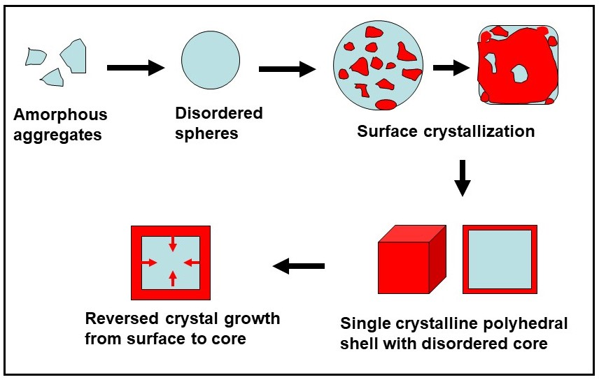
In the last decade, a reversed growth route has been found in many crystal growth processes. In these systems, a single crystal does not develop from a single nucleus. The precursor molecules/ions or nanocrystallites aggregate into some large amorphous or polycrystalline particles. Multiple-nucleation on the surface of the amorphous particles or surface re-crystallization of the polycrystalline particles then takes place, forming a single crystal shell with a regular morphology. Finally, the crystallization extends from the surface to the core to form single crystals. This non-classical crystal growth route often results in some special morphologies, such as core-shell structures, hollow single crystals, sandwich structures, etc. This article gives a brief review of the research into reversed crystal growth and demonstrates that investigation of detailed mechanisms of crystal growth enables us to better understand the formation of many novel morphologies of the crystals. Some unsolved problems are also discussed.

1. Introduction
Crystal growth is a magical phenomenon in nature. Originally separated atoms, ions or molecules can join together with a certain composition, in definite geometric relations, to form a defined crystal structure. Furthermore, the appearance of crystals can be in various regular shapes.
According to the classical theory of crystal growth, a crystal develops in a supersaturated solution with respect to this crystal via nucleation and repeated attachment of the building units, in the forms of atoms, molecules or ions, to a single nucleus. A typical classical growth, therefore, has several characteristics. First, the crystal size increases with the growth time. Second, at any stage of the crystal growth, the particles are single crystals. Finally, crystals often have characteristic polyhedral morphologies. For example, crystals with a cubic structure may have a cubic morphology formed by six equivalent {100} facets, or an octahedral shape with eight equivalent {111} facets, or icositetrahedral morphology formed by 24 equivalent {112} facets, etc. Before the invention of the diffraction method and electron microscopy, geologists often successfully predicted crystal symmetries from the observation of crystal polyhedra by the naked eye or by using an optical microscope.
Two approaches can be used to explain the formation of these polyhedra. One is the kinetic approach as described by the Bravais–Friedel–Donnay–Harker (BFDH) law [1,2,3] and the Hartman–Perdok theory [4]. The crystal growth rate, Rhkl, is different along different crystallographic orientations and inversely proportional to the inter-planar distance, dhkl. Therefore, crystals with a polyhedral morphology are generated by slow growing faces because the fast growing faces grow out so are not displayed in the final crystal habit. Another is thermodynamic approach as elucidated by Curie and Wulff [5,6]. They believed that the equilibrium shape of a free crystal is the shape that minimizes its surface free energy.
The above classical theory depicts crystal growth in some ideal conditions. For example, the crystals are distributed in a solution without attaching to any solid substrate, being so called ‘free crystals’; the crystal surface is clean with no adsorption of other molecules; the chemical pieces approaching to the crystal surface for further growth are the same as the building units of the crystals. However, the environments of crystal growth are often very complicated. The crystal growth rate can be affected by many factors and a growth route may not follow the BFDH law [7,8]. The resulting novel morphologies, e.g., dendrites, hollow crystals, etc., often cannot be explained by using a classical growth route. Therefore, some non-classical crystal growth mechanisms have been proposed. The reversed crystal growth is one of them.
For a developed single crystal in a classical growth route, the growth direction is from its center, the location of the nucleus, to its surface. In reversed crystal growth, however, the growth direction is from the surface to the core. In the last decade, this unusual crystal growth phenomenon has been identified in the crystallization of many synthetic materials, when intermediate specimens at different growth stages were investigated. Some natural occurring minerals also show evidence of reversed crystal growth. Electron microscopy plays an important role in this research field. Particle size and morphology can be revealed by scanning electron microscopy (SEM). Crystal structures of nanocrystallites can be determined by analysing selected area electron diffraction (SAED) patterns and high-resolution transmission electron microscopy (HRTEM) images. The chemical composition and elemental distribution in particles during the crystal growth can be detected using energy dispersive X-ray spectrometry (EDX) in a mode of point analysis or elemental mapping.
2. Reversed Crystal Growth
When many nanocrystallites have developed in a supersaturated solution, they can undergo further growth individually into larger crystals following a classical growth route. However, at very early stages of crystallization, nanocrystallites may aggregate into some large spherical polycrystalline particles. In this case, the environment of further growth of the nanocrystallites inside the particles is largely restrained with limited mass transportation of precursor molecules/ions from the solution to their surface, and limited space available. On the other hand, the nanocrystallites at the outer surface of the spheres may preferentially re-crystallize into a single crystalline shell. The re-crystallization then extends from the surface to the core. In some other cases, the precursors may aggregate into amorphous spheres before any crystallization occurs. Crystallization would then take place on the particle surface and extend from the surface to the core. It is obvious that the early stage aggregation of small chemical pieces is the most important step in reversed crystal growth. A mixture of inorganic and organic charged ions and polymerized large molecules have a high potential of aggregation. Such conditions are often found in synthetic systems for zeolites. By coincidence, the first reported reversed crystal growth was found in the synthesis of zeolite analcime.
2.1. Zeolites
2.1.1. Zeolite Analcime
Icositetrahedral crystals of zeolite analcime were synthesized by Chen et al. [11] using a well established hydrothermal method [12] with a molar composition of synthetic system: 1 SiO2:1 Na2O:0.22 Ni:0.48 Al:1.26 C2H5NH2:0.63 H2SO4:19 H2O. We can understand that the addition of ethylamine as a structure directing agent is crucial in guiding the crystal growth route.
The first crystalline form was nanoplate of zeolite analcime with an average diameter of about 20 nm (bottom inset of Figure 1a). The principal facets of these nanoplates were the {111} planes of the zeolite. The reason for forming such a morphology of the cubic zeolite analcime is still not fully understood. A possible reason is that the (111) surfaces of the crystals are passivated by the adsorbed ethylamine molecules. However, there are eight equivalent {111} planes in the structure. Why are only two of them so special?
Probably also enhanced by ethylamine, these nanoplates did not further grow in the solution, but aggregated into some large discus-shaped particles, about 2 μm in diameter and 400 nm in thickness. Figure 1a shows a typical ‘discus’, which is obviously polycrystalline, since individual nanoplates can be identified at the edge of the particle. However, SAED pattern (top inset of Figure 1a) from a large area of the particle shows single crystal-like pattern. SAED pattern from a profile view of a ‘discus’ shows the same monocrystalline characteristic. Consequently, all the nanoplates in a ‘discus’ are perfectly orientated in three dimensions. Bearing in mind that in later stages of growth, all the ‘discuses’ broke down and all the nanoplates underwent further growth along the [111] direction into nanorods, this implies that the nanoplates in a ‘discus’ linked weakly with organic molecules as an adhesive, rather than intergrowing together directly.
Instead of further growth, the ‘discuses’ aggregated with random orientations into large spherical particles (top inset of Figure 1b). The crystals inside the spheres had difficulties to grow, due to limited space and restricted mass transportation from the solution. The most active site for re-crystallization was the surface of the spheres or the solid–liquid interface. In fact, with a further increase of growth time, many small monocrystalline ‘islands’ developed on the surface of the spheres, as seen smooth domains in Figure 1b. These ‘islands’ extended on the surface of spheres to form an icositetrahedral single crystalline shell (Figure 1d). An interesting phenomenon was that the icositetrahedral morphology already appeared before a perfect single crystal shell formed (Figure 1c).
The most extraordinary picture is the SEM image of the perfect icositetrahedron in Figure 1d. People have no reason to doubt that it is a single crystal. However, breaking the particle enables us to reveal a polycrystalline core with randomly located nanorods, which is covered by only a very thin single crystal shell (Figure 1e).
It was confirmed that, with a long time of hydrothermal treatment, re-crystallization would extend from the surface to the center of the particles. Finally, the whole particles became real single crystals with a hole in the center (Figure 1f). The formation of hollow crystal structure can be understood because when the single crystal shell forms, mass transportation across the shell is difficult and the density of the polycrystalline core is lower than the single crystal.
Chen et al.’s work clearly demonstrates a reversed crystal growth route of zeolite analcime. A final icositetrahedral single crystal did not develop from a single nucleus and the crystallization direction was not from the particle center to the surface. The growth direction was actually opposite. The turning point between the classical and non-classical growth routes was at a very early stage, when the nanoplates aggregated into large polycrystalline spheres instead of growth of individual crystals. A mixture of inorganic and organic ions would enhance such an aggregation.
Li and co-workers also produced hollow zeolite analcime via transformation from zeolite Y. The process includes formation of zeolite Y nanosheets, aggregation of these nanosheets into polycrystalline spheres, phase transformation from zeolite Y to zeolite analcime, surface re-crystallization into a single crystal shell in an icositetrahedral shape, and finally hollow single crystals [13]. It is noted that no surfactants were needed in the synthetic solution. The primary aggregation of zeolite Y nanosheets was due to oriented attachment, which is unusual. The fact is that synthetic systems containing both inorganic and organic ions are very popular in the synthesis of zeolites. The second attractive point raised by the authors is that the grain boundary energy was believed to be the driving force for re-crystallization, and the higher grain boundary energy in exterior than in interior led to reversed crystal growth. Unfortunately, the difference of environments in these two parts was not considered by the authors, which is probably more important.
Zeolite analcime icositetrahedral crystals were also produced by using microwave-assisted hydrothermal synthesis in the presence of sodium carboxymethyl cellulose (CMC) as a green template [14]. The reversed crystal growth was also observed. However, the early stage aggregation of small crystals was quite different from that observed by Chen et al. [11]. The small crystallites aggregated into a hollow shell and developed into radially arranged nanorods. In this work, CMC probably played an important role in the particle aggregation and in the formation of the holes before the surface of the particles re-crystallized into a single crystal shell.
2.1.2. Zeolite A
Zeolite A is an industrial material widely used as a catalyst and an adsorbent. Yao et al. added chitosan into a synthetic system for zeolite A in order to make nanocrystals. A reversed crystal growth route was observed [15].
Before any crystalline phase appeared, the precursor molecules/ions aggregated into large amorphous spheres. Surface re-crystallization then took place on these spheres to form very thin single crystal boxes. The core was still amorphous precursors, which could be washed away in an acid treatment or by electron beam irradiation. The products were empty zeolite A boxes.
After the formation of the single crystal shell, a further hydrothermal treatment was expected to result in an extension of crystallization from the surface to the center. Greer et al. studied the details of the growth under the same conditions [16]. If the density of the core is lower than zeolite A crystals, the final product would be hollow crystals as in zeolite analcime. However, this did not happen in Greer et al.’s synthesis. It was very likely that the amorphous core had a higher density than zeolite A. When the crystallization extended towards the center, pressure built up. Nucleation of zeolite sodalite occurred in the core. Sodalite and zeolite A have almost the same composition and a certain similarity in structure. Zeolite A is constructed by small β-cages and large α-cages, whereas sodalite is built up only by the β-cages. Sodalite has a slightly higher density than zeolite A. High pressure can cause a phase transformation from zeolite A to sodalite. Consequently, Greer et al. observed that sodalite crystals grew up and broke out the zeolite A shell and finally became the only phase in the sample [16].
Another interesting synthesis of zeolite A via reversed crystal growth was performed by Hasan et al. [17]. They also produced a core-shell structure of zeolite A. Instead of producing an amorphous core, they used n-dodecane droplets stabilised with cetyltrimethylammonium bromide to produce multi-hollow polycrystalline core. The phase transformation to zeolite sodalite was, therefore, avoided.
2.1.3. Other Zeolites
Because of the strong interaction between the precursor molecules/ions in the synthetic systems, reversed crystal growth is quite common in zeolites. Synthesis of silicoaluminophosphate SAPO-5 molecular sieves also used several organic and inorganic compounds, aluminum isopropoxide, orthophosphoric acid, silica sol, triethylamine, and acetic acid [18]. These chemicals aggregated into amorphous ellipsoidal particles. Surface re-crystallization of the particles led to a hexagonal prism core-shell structure. The crystallization did not extend to the center of the particles to form hollow hexagonal prisms. Instead, the amorphous core developed a small solid hexagonal prism to form a pencil-like morphology. There seem to be a competition between the extension of re-crystallisation from the side surface of the particles to the core and a self-crystallization in the center. In the case above, both processes occurred simultaneously.
In a synthesis of SAPO-34 from a gelatin-containing gel using a vapour-phase transport method, a reversed crystal growth was also observed [19]. The surface re-crystallization did not start on the faces or edges of a cubic particle, but formed an hourglass-shaped single crystal domain before a completed cubic shell formed.
Hollow hexagonal tubes were observed in a synthesis of apatite-type (Na2.5Bi2.5)(PO4)3(F,OH) [20]. The authors attributed the hole formation in the center of the hexagonal prisms to partial dissolution. However, it is not clear why only the central part of the particles was dissolved. Since the diameter of the tubes increased with the reaction time, the morphology cannot be explained simply by the reversed crystal growth. More experiments may help to fully understand the formation mechanism.
Reversed crystal growth was also observed during synthesis of ZSM-5 (Zeolite Socony Mobil 5). Wu and co-workers produced hollow spheres of ZSM-5 through a surface to core crystallization, when isopropylamine was used as a structure directing agent, which might enhance the early stage aggregation of small particles [21]. SEM images of cross sections of the spheres clearly showed a core-shell structure.
In a synthesis of macroporous monoliths with hollow NaP zeolite, a multiply stepped formation mechanism was observed [22]. Many individual pseudo-spherical particles formed first. Crystallization then occurred on the particle surface to form a core-shell structure, followed by a surface-to-core crystallization, i.e., a reversed crystal growth route. The authors believed that the hollow structures were developed by consuming the core materials during the crystallization.
2.2. Metal Organic Frameworks (MOF)
Similarly, the synthetic systems for metal organic frameworks (MOFs) always contain a mixture of inorganic and organic presursors, from which a strong inter-molecular interaction can be expected. Therefore, we should not be too surprised if a reversed crystal growth mechanism is found in these materials. In a recent review by Schmidt and co-workers on the nucleation and growth of MOFs, they presented a small section of reversed crystal growth of MOFs [23].
2.2.1. MOF-5
When the well established synthesis method was used for MOF-5, the most popularly studied MOF material [24], large cubic crystals did not appear straightforward as reported by Zheng et al. [25]. The first crystalline phase formed was Zn5(OH)8(NO3)2·2H2O microplates, which aggregated with other precursor molecules into large layered particles. The major component was amorphous as detected by X-ray diffraction (XRD).
Nucleation of MOF-5 did not occur in the solution. Instead, a phase transformation from Zn5(OH)8(NO3)2·2H2O to MOF-5 was observed. The latter has a composition of Zn4O(BDC)3, where BDC = 1,4-benzenedicarboxylate. This transformation can be ignited via substitution NO3− groups by BDC groups. The resulted MOF-5 nanocrystallites did not grow up individually, but aggregated into large cubes (Figure 2a). Here we see that the formation of a cubic morphology cannot be explained by the BFDH law, the Hartman–Perdok theory, or Curie and Wulff’s theory. In other words, it has nothing to do with the crystal growth rates because it relies on the aggregation of nanocrystals rather than crystal growth. It has also nothing to do with minimized surface energy since the surface is also polycrystalline. The driving force of forming such a regular morphology is still unknown.
With a longer growth time, the edges of the cubic particles started to re-crystallize into smooth single crystal domains and extended gradually to the face centers (see Figure 2b,c), followed by an extension of re-crystallization from the surface to the core. Finally real single crystal cubes of MOF-5 were produced.
The nanocrystallites on the tough surface of the MOF-5 cubes can linearly link together to form straight nanowires, lying along <100> or <110> directions. The surface presents a textured structure (Figure 2d). Some particles even have a tough surface with a house-of-card structure (Figure 2e) [26]. All these cubes with a tough surface would also undergo re-crystallization to form a single crystal shell (Figure 2f), followed by an extension of crystallization from the surface to the core to achieve a single crystal state.
2.2.2. RHO-Zeolitic Imidazolate Framework (ZIF)
Self et al. synthesized RHO zeolitic imidazolate framework (ZIF) (RHO: a code of a zeolite type), Zn1.33(O.OH)0.33(nim)1.167(pur), (nim: 2-nitroimidazolate, pur: purinate), with a rhombic dodecahedral morphology via a solvothermal process [27], as described in a previous report [28]. It was found that, at an early stage, precursor molecules/ions aggregated into some spherical particles. In 3 h reaction time, nucleation of ZIF took place inside these particles into many nanocrystallites (~40 nm in size), and the particles changed from sphere to a pseudo-rhombic dodecahedral shape. Surface re-crystallization then took place to form a thin single crystal shell in a perfect rhombic dodecahedral shape with 12 exposed {110} facets. It was also found that the crystallinity of the shell increased gradually. The crystallization extended to the center of the particles and single crystals were achieved in 6 weeks.
The nucleation’s sites inside the amorphous particles rather than in the dimethylformamide (DMF) solution implied that the inter-molecular interaction between organic compounds, 2-nitroimidazole, purine, and inorganic zinc nitrate hexahydrate was strong.
Reversed crystallization was also found in other MOFs, such as NUS-6(Zr) and NUS-6(Hf) (NUS: National University of Singapore) via a hydrothermal synthesis [29].
2.3. Metal Oxides
Many metal oxide crystals can develop in a pure inorganic synthetic system, following a classical growth route. However, if organic compounds are added, the precursors or nanocrystallites may aggregate into disordered particles. The classical crystal growth may be suppressed.
2.3.1. ZnO
A good example of non-classical growth of metal oxides was observed in preparing ZnO hexagonal microdisks. These particles can grow on a clean glass slide in a solution containing sodium citrate, zinc nitrate and hexamethylenetetramine. The central part of the hexagonal ZnO microdisks can be selectively dissolved in a weak acidic treatment to form microstadiums. One argument was that the (001) surface was not stable and contained many defects. When detailed steps of the crystal growth of ZnO microdisks were investigated, Self et al. discovered that these very regular hexagonal disks were not single crystals at all. A reversed crystal growth mechanism was therefore proposed [30].
It was found that a polymer layer was first deposited on a glass substrate, on which aggregated the precursor molecules/ions into large spherical particles (Figure 3a). HRTEM images confirmed that ZnO nanocrystals formed inside these particles. During 5 days reaction, the surface of these particles underwent re-crystallization into a hexagonal shape as shown in Figure 3b. If a hexagonal particle formed on the polymer layer was turned over, a view from the bottom of the particle would reveal that there was only a very thin single crystal shell, covering the whole particle except the bottom. This core-shell structure explains why the central area can be easily dissolved.
With further growth, the thickness of the single crystal shell increased. This process could continue until the whole particle became single crystal, because the opening at bottom guaranteed easy mass transportation all the time through the bottom and the porous polymer layer.
In bio-inspired synthesis, ZnO nanoplates (in presence of gelatin) and nanocrystallites (in presence of gum arabic) gathered on both sides of a central plate to form twin particles [31,32]. The driving force to guide such constructions was supposed to be dipole field generated from a double layered plate. TEM images offered evidence of formation of single plates of Zn-containing inorganic/organic composite. Crystallization of ZnO occurred on both sides of a plate and extended from the surfaces towards the center, pushing the organic molecules to the central layer, forming a sandwich-like structure. Since the organic layer was negatively charged, the two ZnO plates would have the outer surface negatively charged, too. The ZnO nanoplates or nanocrystallites in the solution would deposit on the both sides of the sandwich plate very quickly. Here we can see that the formation of the double-layer ZnO plates can be regarded as a two dimensional reversed crystal growth.
2.3.2. Fe2O3
The thermodynamically stable crystal morphology of α-Fe2O3 (hematite) is rhombohedral. However, many novel morphologies of α-Fe2O3 have been fabricated. For example, hollow spheres, nanotubes and nanorings can be synthesized by adding NaH2PO4 and urea to a FeCl3 aqueous solution in a facile hydrothermal method [33]. Polymerization of Fe3+/H2PO4− plays an important role in the formation of these morphologies.
Polymerized precursor molecules/ions further aggregated into large particles, from which β-FeOOH nanorods developed. Because the surface-adsorbed phosphate ions on the nanorods may influence their growth behavor, it is interesting to see that the concentration of phosphate had a significant effect on the final morphology of hematite. A low concentration of phosphate (0.1 mM) led to small number of adsorbed phosphate ions. The electrostatic repulsion force between the nanorods was relatively weak. The nanorods aggregated side by side to form some spindle-shaped particles 150 nm in diameter and 600 nm in length. After decomposition of β-FeOOH, the spindle particles contained evenly distributed α-Fe2O3 nanocrystallites mixed with phosphate ions. The extraordinary phenomenon was that all these separated nanocrystallites were perfectly orientated in three dimensions. The SAED patterns from these particles show single crystal-like patterns. We still do not know whether this ordering is an inheritance from ordering of β-FeOOH nanorods or is due to self-orientation of the α-Fe2O3 nanocrystallites. Re-crystallization occurred on the surface of the spindle particles to form a single crystal shell and extended to the center until all the Fe2O3 nanocrystallites were consumed. Two ends of the core-shell spindle particles were dissolved in a weak acid treatment, leading to the formation of single crystal nanotubes.
When a high concentration of phosphate was used (2.5 or 4.0 mM), a large amount of adsorbed phosphate ions on the β-FeOOH nanorods increased electrostatic repulsion between the nanorods. The separated nanorods decomposed into randomly orientated α-Fe2O3 nanocrystallites with an average size of 5 nm in diameter. These nanocrystallites underwent self-orientated aggregation into some nanoplates. The plates stacked together face-to-face to form some inorganic/organic composite nanodisks. HRTEM images showed that all the nanocrystallites in these nanodisks were self-orientated, not only in the nanoplates but also in between the nanoplates. Surface re-crystallization took place in the polycrystalline nanodisks to create a single crystal shell. When the center of a core-shell nanodisk was dissolved, the particle shape became a single crystal nanoring.
It is demonstrated by the above examples that the formation of α-Fe2O3 single crystal nanotubes and nanorings relies on a reversed crystal growth route [34]. It seems to be a logical consequence when inorganic/organic disordered aggregates form in a synthetic solution and their surface becomes active site for further crystal growth.
2.3.3. Perovskites ABO3
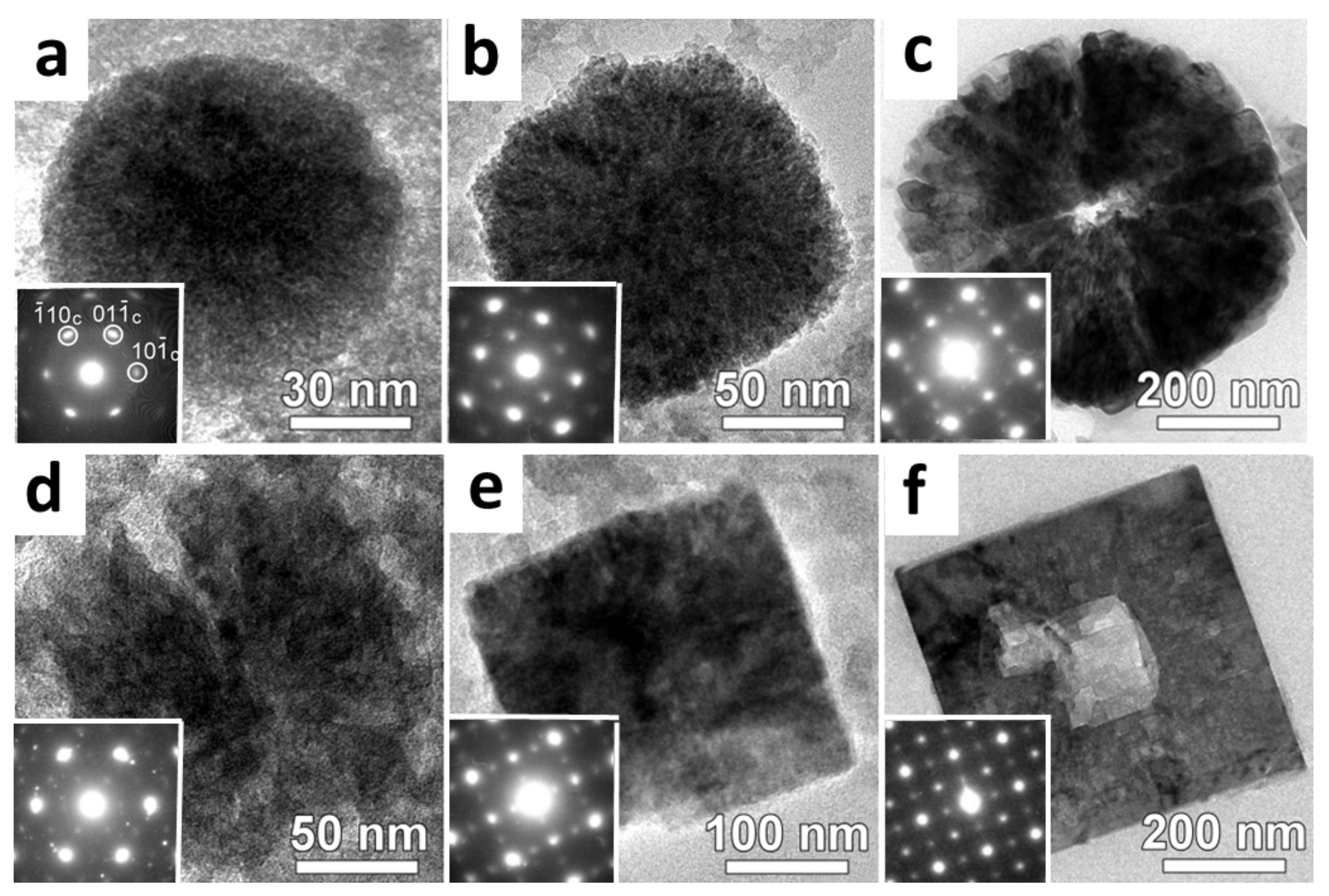
CaTiO3 hollow crystals were solvothermally synthesized using Ca(NO3)2 and Ti(OC4H9)4 as the reactants, PEG-200 (polyethylene glycol 200) as the solvent and NaOH as the mineralization reagent [35]. When no water was added, CaTiO3 nanocrystallites formed inside spherical aggregates of the precursor molecules/ions (Figure 4a). Nanocubes developed gradually in the particles. They self-orientated and self-assembled to form a walnut-like surface. It was noted that the surface of the particles densified first, and such a densification process extended from the surface to the core. Finally a hole in the center appeared (Figure 4b,c). In this case, a single crystal shell never developed. The surface-to-core densification can be regarded as an incomplete surface-to-core re-crystallization in reversed crystal growth.
If 1.25 vol % water was added into the solution, the re-crystallization was greatly enhanced. A cubic single crystal shell was generated as shown in Figure 4d–f. The final product was hollow cubic perovskite boxes. HRTEM images of the specimens at different growth stages showed that the density of the so-called single crystalline shells actually increased with the increase of growth time, due to a reduction of cavity in the crystalline shells.
In hydrothermal synthesis of perovskite SrTiO3 using Sr(NO3)2 and Ti(OC4H9)4 as the precursors, a reversed crystal growth route was identified. The growth kinetic was investigated in detail and three steps distinguished after the formation of disordered spheres were proposed via mathematical modeling, i.e., oriented attachment, size shrinking, and Ostwald ripening [36].
When Ca(NO3)2 in the system for CaTiO3 mentioned above was replaced by Ba(OH)2·8H2O, dodecahedral crystals of BaTiO3 were synthesized [37]. Investigation of specimens at different growth stages revealed that Ti(OC4H9)4 aggregated with PEG to form spherical colloidal particles at the very beginning. Multiple nucleation and growth of nanocrystallites of BaTiO3 took place on the surface of the colloidal particles, and further formed a dodecahedral single crystal shell. A reversed crystal growth was again identified.
In another synthesis starting with a mixture of TiO2 sols and Ba(NO3)2 under a hydrothermal condition, gapped hollow BaTiO3 nanospheres, 100 nm in diameter, were produced [38]. It was believed that the formation of such morphology was due to a combination of the orientated attachment and reversed crystal growth. Small nanoparticles, 5–10 nm in size, formed first. They self-orientated and self-assembled into some large spherical particles. Re-crystallization of these loosely aggregated nanospheres then occurred from the particle surface towards the core, forming hollow particles. A close look at the shape of these hollow particles, one can find they are not quite spherical, but a dodecahedral shape although the edges are not very sharp. The aggregation of nanocrystallites should be enhanced by a large amount of organic molecules/ions, such as tetrabutyl ions, glacial acetic acid, isopropyl alcohol, etc. Another point was that, since the hollow particles were not sealed, the holes could be filled gradually with a long reaction time.
A reversed crystal growth route was also identified in microwave-assisted hydrothermal synthesis of BaZrO3 using zirconyl chloride octahedrate ZrOCl2·8H2O and barium chloride dehydrate BaCl2·2H2O as precursors [39]. Nanoparticles aggregated into spherical particles with a low crystallinity and probably a low density (porous). Surface re-crystallization led to a decaoctahedral shell followed by an extension of crystallization from the surface to the core.
In another synthesis of perovskite-type crystals, SrZrO3 hollow cuboidal nanoboxes were fabricated via a simple hydrothermal route from concentrated KOH solutions without any organic or inorganic templates [40]. It was observed that the particle morphology evolution with the reaction time was successively solid microparticles, core-shell particles and hollow nanocrystals driven by the Ostwald ripening process. It is noted that the synthetic system was quite simple, dissolving Sr(NO3)2 and ZrOCl2·8H2O in a concentrated KOH solution, followed by a hydrothermal treatment. The crystal growth process is similar to that of zeolite A as discussed above [15,16]. The precursor molecules and small crystallites aggregated into disordered particles. Surface re-crystallization led to a single crystal cubic shell. A typical reversed crystal growth showed the extension of crystallization from the surface to the core via an Ostwald ripening process.
Reversed crystal growth often leads to hollow crystals as demonstrated in the above examples. However, not all the holes in crystals are resulted from reversed crystal growth. For example, Yu et al. synthesized rutile TiO2 by a biologic molecules-assisted hydrothermal process [41]. In a spherical TiO2 particle there was a hole at the center. The microstructure of these spheres looked like spherulite consisting of radially arranged nanorods. These spherulite particles normally have a core as a base for the growth of the nanorods and the formation mechanism is quite different from reversed crystal growth [42,43].
2.4. Biomimetic CaCO3
Crystallization of CaCO3 is probably one of the most important natural processes of mineralization. Many cases of CaCO3 deposition in natural environments are not pure inorganic process. Nucleation and crystal growth of CaCO3 in hot spring pools, riverbeds and seabeds are often biotic processes, i.e., Ca2+ and CO32− are captured by biological substances. The common term of the important substance is called the extracellular polymeric substance (EPS). Nucleation of CaCO3 therefore occurs inside the inorganic/biological composite aggregates. We can expect to get some evidences of reversed crystal growth in natural environment, when calcite specimens in naturally occurring travertine crust are investigated by using SEM.
Figure 5a shows an SEM image of a travertine sample collected from at Erdaohai in Munigou Valley National Park, which is located in the northern part of the Sichuan Province, China. The bulk particles are polycrystalline, consisting of many small calcite crystallites. Figure 5b is an SEM image of some bulk particles with their surface partially re-crystallized to smooth plates [44]. The microstructures matches an important process in the reversed crystal growth, aggregation of nanocrystallites followed by surface re-crystallization forming a core-shell structure.
Calcite crystals were prepared by a group of third year undergraduate students at the University of St Andrews in a biomimetic synthesis using Ca(NO3)2, urea, and gum arabic. The latter was expected to have the same function as EPS in the mineralization [45]. The particles at early stages showed partial surface re-crystallization. Figure 5c is a polycrystalline spherical particle with a few single crystal islands on its surface. Figure 5d is another polycrystalline particle with six smooth single crystal plates developed on the surface. The interesting feature is that, although these six plates are separated and the core seems to be polycrystalline, the location and relation of these plates perfectly match the six facets of the final rhombohedral crystals. The reason for such a wonderful construction is still unknown.
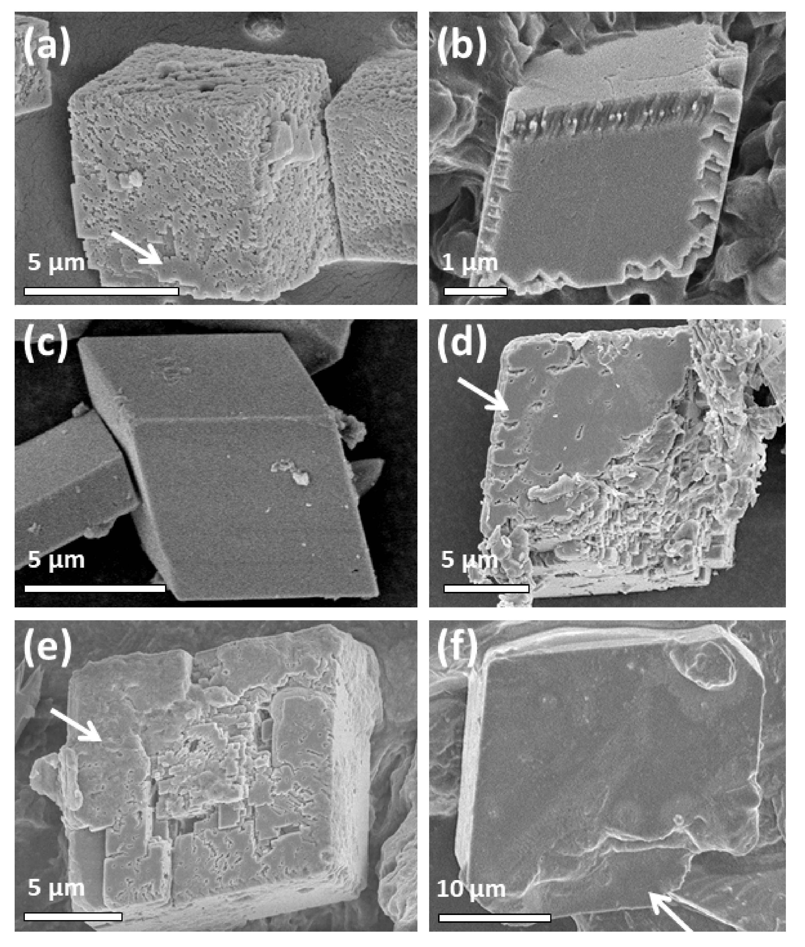
Unlike natural samples, synthetic specimens can be collected at different growth times easily. Therefore, morphology evolution can be displayed. Figure 6 shows calcite particles prepared using chitosan as a promoter with different growth times. After calcite nanocrystallites formed, they aggregated into large rhombohedral particles (Figure 6a). Again the formation of such a regular shape of a polycrystalline particle is rare and its mechanism is still unknown. These particles underwent surface re-crystallization to form six smooth plates (Figure 6b). The single crystal plates expand to cover the whole surface (Figure 6c), forming a rhombohedral core-shell structure, as if the shell was broken, and the revealed core is still polycrystalline (Figure 6d). The thickness of the single crystal shell would increase with a longer growth time (Figure 6e), until the whole particle became a single crystal (Figure 6f). Consequently, Figure 6 shows a complete reversed crystal growth process.
2.5. Metal Nanocrystals
Metallic crystals normally develop in a classical way. However, in some circumstances, aggregation of metal nanocrystallites occurs and the crystal growth mechanism can be changed. In the formation of Mg2SiO4 fishbone-like fractal nanostructures, Co nanocrystals, as a catalyst, grew simultaneously with the Mg2SiO4 nanorods. Therefore, it is possible to observe Co nanoparticles at different growth stages from a single fishbone-like particle [46]. HRTEM images revealed that Co deposited on the surface of the nanorods as individual atoms. Co atoms gathered to form nanocrystallites about 2 nm in diameter. For an unknown reason, these nanocrystallites stopped further growth. Instead, they aggregated into some polycrystalline clusters. Only when the cluster size increased to a certain value did they re-crystallize into single crystals. The process of re-crystallization was not shown. Therefore, we do not know whether it started from the particle surface and extended to the core or along an opposite direction in the gas–solid synthetic system. But it is confirmed that each Co crystal developed from multiple nucleation.
In a synthesis of CuPt alloy performed by Yu et al., a reversed crystal growth seemed to be relatively clear [47]. The synthetic system contained platinum acetylacetonate [Pt(acac)2], CuSO4·5H2O, hexadecylamine (HDA), and ethylene glycol. The precursors aggregated into amorphous spherical particles. Multiple nucleation took place near the surface of each particle, forming a core-shell structure, i.e., an amorphous core covered by a single crystal shell. Finally, solid single crystals formed.
2.6. Organic Crystals
If MOFs can be regarded as organic/inorganic complexes, it is of great interest to see if pure organic crystals can also grow via a reversed growth route. Sander et al. demonstrated the first and a beautiful example to confirm this possibility [48]. Hollow rhombic-dodecahedral crystals of the C-methylcalix[4]resorcinarene (CMCR) hexamer were synthesized by dissolving CMCR in boiling nitrobenzene (NO2Ph) followed by a sonochemical treatment. Many organic molecules, especially with a large molecular weight, can undergo quick self-assembly driven by inter-molecular forces. After sonication for only 45 s, CMCR molecules formed nanocrystals with an average diameter of about 70 nm. After 2 min ultrasonic irradiation, these nanocrystals aggregated into large particles, over 1 μm in diameter. Some smooth islands formed on the surface and the re-crystallization extended to the whole surface of the particles, forming a rhombic-dodecahedral morphology. The final product was hollow dodecahedral crystals of CMCR.
3. Conclusions
Since the first report of reversed crystal growth in the synthesis of zeolite analcime [11], this non-classical crystallization has been found in many inorganic materials. The research realm also extends to organic/inorganic complexes, and to pure organic crystals. It cannot replace the classical crystal growth theory, but is a complementary mechanism of the latter.
In a typical classical crystal growth, it is assumed that nucleation occurs in a melt/vapor/solution and crystal growth is due to layer-by-layer deposition of the building units of the crystals. However, early stage aggregation of precursor molecules/ions can change the crystal growth route. The nucleation sites may move to a solid phase. The chemical pieces moving to the crystal surface may not be the same as the building units of the crystals. Crystallization or re-crystallization may follow the direction from the surface to the core. This so-called reversed crystal growth route can lead to some novel morphologies. One typical example is the formation of some hollow crystals.
The reversed crystal growth can explain the formation of many hollow crystals, which have a high potential in many applications, such as drug delivery [49], photocatalysis [36], etc. A more general term can be called reversed condensation. A condensation from surface to core may form a hollow construction in natural processes. Such constructed products can be as small as enhydro agate stone, or as large as planets such as the Earth or the Moon.
When we understand that the early stage aggregation is the turning point, we can control the synthetic conditions to change the crystal growth route. As demonstrated by Vasylkiv et al., in a synthesis of Fe2O3 crystals, they successfully changed the growth mechanism from the classical route to the reversed crystal growth mechanism by adding chitosan [50]. It is true indeed that the knowledge of reversed crystal growth enables us to better understand the formation mechanisms of many novel morphologies of crystals and to have more freedom to control growth in crystal engineering.
Conflicts of Interest
The author declares no conflict of interest.
References
- Bravais, A. Études Crystallographic; Gauthier-Villars: Paris, France, 1866. [Google Scholar]
- Friedel, M.G. Étudessurla loi de Bravais. Bull. Soc. Fr. Mineral Cristallogr. 1907, 30, 326–455. [Google Scholar]
- Donnay, D.; Harker, D. A new law of crystal morphology extending the law of Bravais. Am. Mineral. 1937, 22, 446–467. [Google Scholar]
- Hartman, P.; Perdok, W.G. On the relations between structure and morphology of crystals. II. Acta Crystallogr. 1955, 8, 521–524. [Google Scholar] [CrossRef]
- Curie, P. Sur la formation des cristaux et sur les constants capillaires de leursdifférentes faces. Bull. Soc. Fr. Mineral Cristallogr. 1885, 8, 145–150. [Google Scholar]
- Wulff, G. Zur frage der geschwindigkeit des wachstums und der auflösung der kristallflächen. Z. Kristallogr. 1901, 34, 449–530. [Google Scholar]
- Prywer, J. On the crystal geometry influence on the growth of fast-growing surfaces. J. Phys. Chem. Solids 2002, 63, 493–501. [Google Scholar] [CrossRef]
- Prywer, J. Explanation of some peculiarities of crystal morphology deduced from the BFDH law. J. Cryst. Growth 2004, 270, 699–710. [Google Scholar] [CrossRef]
- Zhou, W.Z. Reversed crystal growth: Implications for crystal engineering. Adv. Mater. 2010, 22, 3086–3092. [Google Scholar] [CrossRef]
- Greer, H.F.; Yu, F.J.; Zhou, W.Z. Early stages of non-classic crystal growth. Sci. China Chem. 2011, 54, 1867–1876. [Google Scholar] [CrossRef]
- Chen, X.Y.; Qiao, M.H.; Xie, S.H.; Fan, K.N.; Zhou, W.Z.; He, H.Y. Self-construction of core-shell and hollow zeolite analcime icositetrahedra: A reversed crystal growth process via oriented aggregation of nanocrystallites and recrystallization from surface to core. J. Am. Chem. Soc. 2007, 129, 13305–13312. [Google Scholar] [CrossRef]
- Ueda, S.; Koizumi, M. Crystallization of analcime solid solutions from aqueous solutions. Am. Mineral. 1979, 64, 172–179. [Google Scholar]
- Wang, Y.; Li, X.G.; Xue, Z.Y.; Dai, L.S.; Xie, S.H.; Li, Q.Z. Preparation of zeolite ANA crystal from zeolite Y by in situ solid phase iso-structure transformation. J. Phys. Chem. B 2010, 114, 5747–5754. [Google Scholar] [CrossRef] [PubMed]
- Samadi-Maybodi, A.; Pourali, S.M. Microwave-assisted hydrothermal green synthesis of analcime icositetrahedra: Insight into intermediates formed in the reversed crystal growth process. Eur. J. Inorg. Chem. 2014, 2014, 1204–1210. [Google Scholar] [CrossRef]
- Yao, J.F.; Li, D.; Zhang, X.Y.; Kong, C.H.; Yue, W.B.; Zhou, W.Z.; Wang, H.T. Cubes of zeolite A with an amorphous core. Angew. Chem. Int. Ed. 2008, 47, 8397–8399. [Google Scholar] [CrossRef] [PubMed]
- Greer, H.; Wheatley, P.S.; Ashbrook, S.E.; Morris, R.E.; Zhou, W.Z. Early stage reversed crystal growth of zeolite A and its phase transformation to sodalite. J. Am. Chem. Soc. 2009, 131, 17986–17992. [Google Scholar] [CrossRef] [PubMed]
- Hasan, F.; Singh, R.; Webley, P.A. Formation of LTA zeolite crystals with multi-hollow polycrystalline core–shell structure via aggregation–recrystallization route in presence of emulsion droplets. Microp. Mesop. Mater. 2012, 160, 75–84. [Google Scholar] [CrossRef]
- Yang, Q.; Li, M.; Zeng, C.F.; Zhang, L.X. Hydrothermal synthesis of pencil-like SAPO-5 and observation of its reversed crystal-growth process. Chem. Eur. J. 2013, 19, 365–371. [Google Scholar] [CrossRef]
- Gong, J.; Tong, F.; Ji, X.B.; Zeng, C.F.; Wang, C.Q.; Lv, Y.N.; Zhang, L.X. Hollow SAPO-34 cubes with hierarchically organized internal structure. Cryst. Growth Des. 2014, 14, 3857–3863. [Google Scholar] [CrossRef]
- Zhou, Y.; Huang, Y.-X.; Pan, Y.M.; Mi, J.-X. Single-crystal microtubes of a novel apatite-type compound, (Na2.5Bi2.5)(PO4)3(F,OH), with well-faceted hexagonal cross sections. CrystEngComm 2009, 11, 1863–1867. [Google Scholar] [CrossRef]
- Wang, Z.; Liu, Y.; Jiang, J.; He, M.; Wu, P. Synthesis of ZSM-5 zeolite hollow spheres with a core/shell structure. J. Mater. Chem. 2010, 20, 10193–10199. [Google Scholar] [CrossRef]
- Huang, Y.; Dong, D.; Yao, J.; He, L.; Ho, J.; Kong, C.; Hills, A.J.; Wang, H. In situ crystallization of macroporous monoliths with hollow NaP zeolite structure. Chem. Mater. 2010, 22, 5271–5278. [Google Scholar] [CrossRef]
- Van Vleet, M.J.; Weng, T.T.; Li, X.Y.; Schmidt, J.R. In situ, time-resolved, and mechanistic studies of metal−organic framework nucleation and growth. Chem. Rev. 2018, 118, 3681–3721. [Google Scholar] [CrossRef]
- Hafizovic, J.; Bjørgen, M.; Olsbye, U.; Dietzel, P.D.C.; Bordiga, S.; Prestipino, C.; Lamberti, C.; Lillerud, K.P. The inconsistency in adsorption properties and powder XRD data of MOF-5 is rationalized by framework interpenetration and the presence of organic and inorganic species in the nanocavities. J. Am. Chem. Soc. 2007, 129, 3612–3620. [Google Scholar] [CrossRef] [PubMed]
- Zheng, C.M.; Greer, H.F.; Chiang, C.-Y.; Zhou, W.Z. Microstructural study of formation mechanism of metal-organic framework MOF-5. CrystEngComm 2014, 16, 1064–1070. [Google Scholar] [CrossRef]
- Greer, H.F.; Liu, Y.H.; Greenaway, A.; Wright, P.A.; Zhou, W.Z. Synthesis and formation mechanism of textured MOF-5. Cryst. Growth Des. 2016, 16, 2104–2111. [Google Scholar] [CrossRef]
- Self, K.; Telfer, M.; Greer, H.F.; Zhou, W.Z. Reversed crystal growth of zeolite imidazolate framework RHO-ZIF. Chem. Euro. J. 2015, 21, 19090–19095. [Google Scholar] [CrossRef] [PubMed]
- Kahr, J.; Mowat, J.P.S.; Slawin, A.M.Z.; Morris, R.E.; Fairen-Jimenez, D.; Wright, P.A. Synthetic control of framework zinc purinate crystallisation and properties of a large pore, decorated, mixed-linker RHO-type ZIF. Chem. Commun. 2012, 48, 6690–6692. [Google Scholar] [CrossRef] [PubMed]
- Hu, Z.G.; Peng, Y.W.; Gao, Y.J.; Qian, Y.H.; Ying, S.M.; Yuan, D.Q.; Horike, S.; Ogiwara, N.; Babarao, R.; Wang, Y.X.; et al. Direct synthesis of hierarchically porous metal−organic frameworks with high stability and strong Brønsted acidity: The decisive role of hafnium in efficient and selective fructose dehydration. Chem. Mater. 2016, 28, 2659–2667. [Google Scholar] [CrossRef]
- Self, K.; Zhou, H.J.; Greer, H.F.; Tian, Z.R.; Zhou, W.Z. Reversed crystal growth of ZnO microdisks. Chem. Commun. 2013, 49, 5411–5413. [Google Scholar] [CrossRef]
- Greer, H.F.; Zhou, W.Z.; Liu, M.H.; Tseng, Y.H.; Mou, C.Y. The origin of ZnO twin crystals in bio-inspired synthesis. CrystEngComm 2012, 14, 1247–1255. [Google Scholar] [CrossRef]
- Liu, M.H.; Tseng, Y.H.; Greer, H.F.; Zhou, W.Z.; Mou, C.Y. Dipole field guided orientated attachment of nanocrystals to twin-brush ZnO mesocrystals. Chem. Euro. J. 2012, 18, 16104–16113. [Google Scholar] [CrossRef] [PubMed]
- Liu, Z.; Yu, R.T.; Dong, Y.P.; Li, W.; Zhou, W.Z. Preparation of α-Fe2O3 hollow spheres, nanotubes, nanoplates and nanorings as high efficient Cr(VI) adsorbents. RSC Adv. 2016, 6, 82854–82861. [Google Scholar] [CrossRef]
- Chen, J.L.; Macfarlane, S.; Zhang, C.X.; Yu, K.; Zhou, W.Z. Chemistry of hydrolysis of FeCl3 in the presence of phosphate to form hematite nanotubes and nanorings. Cryst. Growth Des. 2017, 17, 5975–5983. [Google Scholar] [CrossRef]
- Yang, X.F.; Fu, J.X.; Jin, C.J.; Chen, J.; Liang, C.L.; Wu, M.M.; Zhou, W.Z. Formation mechanism of CaTiO3 hollow crystals with different microstructures. J. Am. Chem. Soc. 2010, 132, 14279–14287. [Google Scholar] [CrossRef] [PubMed]
- Zhan, H.Q.; Chen, Z.-G.; Zhuang, J.L.; Yang, X.F.; Wu, Q.L.; Jiang, X.P.; Liang, C.L.; Wu, M.M.; Zou, J. Correlation between multiple growth stages and photocatalysis of SrTiO3 nanocrystals. J. Phys. Chem. C 2015, 119, 3530–3537. [Google Scholar] [CrossRef]
- Zhan, H.Q.; Yang, X.F.; Wang, C.M.; Chen, J.; Wen, Y.P.; Liang, C.L.; Greer, H.F.; Wu, M.M.; Zhou, W.Z. Multiple nucleation and crystal growth of barium titanate. Cryst. Growth Des. 2012, 12, 1247–1253. [Google Scholar] [CrossRef]
- Gao, J.B.; Shi, H.Y.; Yang, J.; Li, T.; Zhang, R.; Chen, D.L. Influencing factor investigation on dynamic hydrothermal growth of gapped hollow BaTiO3 nanospheres. Nanoscale Res. Lett. 2015, 10, 329. [Google Scholar] [CrossRef] [PubMed]
- Moreira, M.L.; Andrés, J.; Mastelaro, V.R.; Varela, J.A.; Longo, E. On the reversed crystal growth of BaZrO3 decaoctahedron: Shape evolution and mechanism. CrystEngComm 2011, 13, 5818–5824. [Google Scholar] [CrossRef]
- Ye, T.; Dong, Z.H.; Zhao, Y.N.; Yu, J.G.; Wang, F.Q.; Guo, S.K.; Zou, Y.C. Controllable fabrication of perovskite SrZrO3 hollow cuboidal nanoshells. CrystEngComm 2011, 13, 3842–3847. [Google Scholar] [CrossRef]
- Liu, S.J.; Gong, J.Y.; Hu, B.; Yu, S.H. Mesocrystals of rutile TiO2: Mesoscale transformation, crystallization, and growth by a biologic molecules-assisted hydrothermal process. Cryst. Growth Des. 2009, 9, 203–209. [Google Scholar] [CrossRef]
- Wu, S.T.; Chiang, C.-Y.; Zhou, W.Z. Formation mechanism of CaCO3 spherulites in myostracum layer of limpet shells. Crystals 2017, 7, 319. [Google Scholar] [CrossRef]
- Greer, H.F.; Liu, M.-H.; Mou, C.-Y.; Zhou, W.Z. Dipole field driven morphology evolution in biomimetic vaterite. CrystEngComm 2016, 18, 1585–1599. [Google Scholar] [CrossRef]
- Greer, H.F.; Zhou, W.Z.; Guo, L. Reversed crystal growth of calcite in naturally occurring travertine crust. Crystals 2017, 7, 36. [Google Scholar] [CrossRef]
- Ritchie, A.; Watson, M.; Turnbull, R.; Lu, Z.; Telfer, M.; Gano, J.; Self, K.; Greer, H.F.; Zhou, W.Z. Reversed crystal growth of rhombohedral calcite in the presence of chitosan and gum Arabic. CrystEngComm 2013, 15, 10266–10271. [Google Scholar] [CrossRef]
- Xie, S.H.; Zhou, W.Z.; Zhu, Y.Q. Formation mechanism of Mg2SiO4 fishbone-like fractal nanostructures. J. Phys. Chem. B 2004, 108, 11561–11566. [Google Scholar] [CrossRef]
- Yu, F.J.; Zhou, W.Z. Alloying and dealloying of CuPt bimetallic nanocrystals. Prog. Nat. Sci. Mater. Int. 2013, 23, 331–337. [Google Scholar] [CrossRef]
- Sander, J.R.G.; Bučar, D.-K.; Baltrusaitis, J.; MacGillivray, L.R. Organic nanocrystals of the resorcinarene hexamer via sonochemistry: Evidence of reversed crystal growth involving hollow morphologies. J. Am. Chem. Soc. 2012, 134, 6900–6903. [Google Scholar] [CrossRef] [PubMed]
- Lv, R.C.; Yang, P.P.; He, F.; Gai, S.L.; Yang, G.X.; Lin, J. Hollow structured Y2O3:Yb/Er−CuxS nanospheres with controllable size for simultaneous chemo/photothermal therapy and bioimaging. Chem. Mater. 2015, 27, 483–496. [Google Scholar] [CrossRef]
- Vasylkiv, O.; Bezdorozhev, O.; Sakka, Y. Synthesis of iron oxide nanoparticles with different morphologies by precipitation method with and without chitosan addition. J. Ceramic Soc. Jpn. 2016, 124, 489–494. [Google Scholar] [CrossRef]
Figure 1.
Electron microscopic observation (a, transmission electron microscopy (TEM) and others, scanning electron microscopy (SEM) images) of zeolite analcime particles with different growth times. (a) A discus-shaped aggregate of nanoplates after growth for 16 h. Top inset is the corresponding selected area electron diffraction (SAED) pattern and bottom inset shows an individual nanoplate. (b) Surface of a polycrystalline microsphere after growth for 20 h. Top inset shows a whole particle and bottom inset is a short nanorod. The arrow indicates the preferred growth direction of the nanoplates along the [111] zone axis. (c) A typical particle in 24 h sample. (d,e) Icositetrahedral analcime particles with growth time of 8 days. (f) A hollow single crystal after growth of 22 days. Reprinted with permission from [11]. Copyright 2007, American Chemical Society.

Figure 2.
SEM images of metal organic framework (MOF-5) particles. (a) An individual polycrystalline cubic particle with a rough surface. (b) A cube when the surface partially re-crystallized. (c) A cube with a single crystal shell nearly completed. (d) Typical textured cubes. Inset is an enlarged image. (e) A typical MOF-5 cube with a woven surface. Inset is an enlarged image showing a house-of-cards structure. (f) A MOF-5 cube with a single crystal shell. (a–c,f) Reproduced from [25] with permission from The Royal Society of Chemistry. (d,e) Reprinted with permission from [26]. Copyright 2016, American Chemical Society.

Figure 3.
SEM images of (a) a polycrystalline aggregate, (b) a typical hexagonal microdisk of ZnO, and (c) a crushed open ZnO microdisks with reaction time of 5 days. The arrows indicate the thickness of the single crystal shell. Reproduced from [30] with permission from The Royal Society of Chemistry.

Figure 4.
TEM images and corresponding SAED patterns of particles during growth of CaTiO3 obtained from the water-free system with different crystal growth times: (a) 1, (b) 2, and (c) 5 h. TEM images and SAED patterns obtained from the system containing 1.25 vol % water with different crystal growth times: (d) 1, (e) 2, and (f) 5 h. Reprinted with permission from [35]. Copyright 2010, American Chemical Society.

Figure 5.
(a,b) SEM images of calcite particles found in the travertine specimens (after [44]). (a) Calcite aggregate composed of a dense arrangement of calcite nanoparticles. The arrows mark the extracellular polymeric substance (EPS). (b) Low magnification image showing calcite particles with a relatively smooth surface. (c,d) SEM images of calcite crystals from samples prepared in the gum arabic containing system with growth times of 2 h. (c,d) Reproduced from [45] with permission from The Royal Society of Chemistry.

Figure 6.
SEM images of calcite crystals prepared in the presence of chitosan. Different incubation times of (a) 2 h, (b) 4 h, (c,d) 23 h, (e) 3 days and (f) 9 days were applied. The particles in (d–f) were pre-crushed in order to reveal their inner structures. The arrow in (a) indicates a large single crystal region on the surface of the rhombohedral particle. The arrows in (d) and (e) point at the single crystal shell whilst the arrow in (f) indicates a single crystal core. Reproduced from [45] with permission from The Royal Society of Chemistry.

© 2018 by the author. Licensee MDPI, Basel, Switzerland. This article is an open access article distributed under the terms and conditions of the Creative Commons Attribution (CC BY) license (http://creativecommons.org/licenses/by/4.0/).
Share and Cite
MDPI and ACS Style
Zhou, W. Reversed Crystal Growth. Crystals 2019, 9, 7. https://doi.org/10.3390/cryst9010007
AMA Style
Zhou W. Reversed Crystal Growth. Crystals. 2019; 9(1):7. https://doi.org/10.3390/cryst9010007
Chicago/Turabian StyleZhou, Wuzong. 2019. "Reversed Crystal Growth" Crystals 9, no. 1: 7. https://doi.org/10.3390/cryst9010007
APA StyleZhou, W. (2019). Reversed Crystal Growth. Crystals, 9(1), 7. https://doi.org/10.3390/cryst9010007
Note that from the first issue of 2016, this journal uses article numbers instead of page numbers. See further details here.