Article

Lattice Correspondence and Growth Structures of Monoclinic Mg4Zn7 Phase Growing on an Icosahedral Quasicrystal

Research Center for Structural Materials, National Institute for Materials Science (NIMS), Sengen 1-2-1, Tsukuba, Ibaraki 305-0047, Japan
*
Author to whom correspondence should be addressed.
Current address: Erich Schmid Institute of Materials Science, 8700 Leoben, Austria.
Crystals 2018, 8(5), 194; https://doi.org/10.3390/cryst8050194
Submission received: 11 April 2018 / Revised: 26 April 2018 / Accepted: 27 April 2018 / Published: 1 May 2018
(This article belongs to the Special Issue Structure and Properties of Quasicrystalline Materials)

Abstract

:
Mg 4 Zn 7 phase, with a monoclinic unit cell, a layered structure and a unique axis showing pseudo-tenfold symmetry, grows over icosahedral quasicrystalline phase in a manner similar to a decagonal quasicrystal. In this study, the relationship of this phase to icosahedral quasicrystal is brought out by a transmission electron microscopy study of Mg 4 Zn 7 phase growing on icosahedral phase in a cast Mg-Zn-Y alloy. Lattice correspondences between the two phases have been determined by electron diffraction. Planes related to icosahedral fivefold and pseudo-twofold symmetry are identified. Possible orthogonal cells bounded by twofold symmetry-related planes have been determined. Mg 4 Zn 7 phase growing on an icosahedral phase exhibits a number of planar faults parallel to the monoclinic axis, presumably to accommodate the quasiperiodicity at the interface. Two faults were identified, which were on {200} and { 2 ¯ 01} planes. Their structures have been determined by high resolution imaging in TEM. They produce two different unit cells at the interface.

Graphical Abstract

1. Introduction

The first report of an icosahedral quasicrystal phase exhibiting the fivefold symmetry forbidden in classical crystallography and a quasiperiodic translational order took the scientific community by surprise [1]. The reciprocal space of this crystal are densely filled with spots of various intensities, and are characterized by an icosahedral symmetry which has six fivefold symmetry axes, 10 threefold symmetry axes (through the twenty triangular faces) and 15 twofold symmetry axes. Soon after, a tenfold symmetry two-dimensional quasicrystal was also reported, called the decagonal phase [2,3]. The unique tenfold symmetry axis in such a lattice can be generated by reflection of a fivefold axis. The lattice is periodic along the tenfold symmetry axis. Growth of the decagonal phase over an icosahedral phase has often been reported, in which the tenfold axis of the decagonal quasicrystal grows along a fivefold axis of the icosahedral phase [4,5,6]. The structure of quasicrystals are described as tilings; Penrose tilings (in two-dimensions and generalized to three-dimensions) show fivefold and tenfold symmetry [7,8]. These tilings consist of two kinds of tiles, a thin rhombus (acute angle of 36 ) and a thick rhombus (acute angle of 72 ). There are crystalline phases with large unit cells and a complex structure close to quasicrystalline phases. Called rational approximant structure (RAS) or phases, they are crystalline, but show icosahedral motifs in the unit cells [9,10]. Although the reciprocal spots in their diffraction patterns are periodically arranged, their intensities bring out motifs characteristic of atom clusters of icosaehdral or related symmetry. There are a number of well known RAS to the icosahedral phase and the decagonal phase in Al-based alloys. The icosahedral approximants usually have cubic or orthorhombic unit cells, while decagonal approximants are usually orthorhombic or monoclinic, whose structures can be described as layered.
Apart from the quasicrystal phases reported in numerous aluminum alloys, icosahedral [11,12] and decagonal [13,14,15] quasicrystals are known to exist in Zn-Mg-RE (RE = Y, Gd, Tb, Dy, Ho or Er rare earth element) alloys too. A decagonal phase has been reported but is not commonly observed [13,15]. However, no parallels of approximant phases to aluminum alloys have been reported in these alloys. The icosahedral phase in Zn-Mg-Y system is Mg 3 ZnY 6 . It forms a two-phase field in the ternary phase diagram [16], and therefore can also exist in magnesium rich alloys. There are two binary Mg-Zn phases that are commonly found in the binary Mg-Zn alloys and magnesium-rich Mg-Zn-Y alloys [16,17]. The MgZn 2 phase (Frank-Kasper phase) has a hexagonal unit cell of a = 5.15 Å and c = 8.48 Å [18]. Its structure can be described as atomic layers of pentagonal coordinations, as shown in Figure 1a. A set of inverted layers generate icosahedral coordinations. Another is a monoclinic phase Mg 4 Zn 7 (a = 25.96 Å, b = 5.24 Å, c = 14.28 Å, β = 102.5 , space group C 2 / m [19]). It can also be described by similar units as the MgZn 2 phase, as shown in Figure 1b. This phase has been shown to be related to the icosahedral phase by a projection method [20]. The MgZn 2 and Mg 4 Zn 7 are often found to coexist because of similar structural units of rhombohedral tiles connecting icosahedral coordinating units [21,22,23,24,25,26,27,28]. The same units also create C14 and C15 coordination phases [25,26].
Similar to the observations in aluminum alloys, a decagonal phase forming on icosahedral phase has also been reported in Mg-Zn-Y alloys [15]. Besides this, formation of Mg 4 Zn 7 on decagonal phase has also been reported in the same alloys, with orientation relationship [D10]‖[010] Mg 4 Zn 7 , [D2 a ]‖[ 4 ¯ 01] Mg 4 Zn 7 and [D2 b ]‖[ 1 ¯ 02] Mg 4 Zn 7 , where D10 represents the unique tenfold symmetry axis and D2 a and D2 b are two twofold axes perpendicular to D10 and separated from each other by π 20 [15]. The same study also determined the composition of the decagonal phase to be about Mg 35 Zn 60 Y 4.4 , while the Mg 4 Zn 7 phase did not show any yttrium. In dilute Mg-Zn-Y/RE alloys, however, no decagonal phase is reported. The Mg 4 Zn 7 phase is often observed to grow directly over the icosahedral phase. Figure 2 shows an example of Mg 4 Zn 7 growing on an icosahedral phase in an extruded Mg-Zn-Ho alloy [29]. The Fast Fourier Transform (FFT) (inset in Figure 2a) shows the icosahedral phase to be in a twofold symmetry zone axis orientation. Fivefold (5f) and twofold (2f) reciprocal directions are marked. The FFT of Figure 2b shows that the Mg 4 Zn 7 phase grows with its c-axis along a fivefold axis. There appears to be a high density of planar faults along the c-axis, producing a continuous diffuse intensity on the a c plane. Thus, there are similarities to the growth of decagonal phase growing over an icosahedral phase [4,5,6]. The interplanar spacing of the {020} Mg 4 Zn 7 (2.62 Å) is nearly coincident with the strongest spot {422222} along a fivefold axis (spacing 2.43 Å; Elser’s indexing is followed here [30]).
In this study, we have investigated the structural relationship of the Mg 4 Zn 7 to the icosahedral quasicrystalline phases by electron diffraction and determined the nature of lattice defects by high resolution transmission electron microscopy.

2. Experimental Procedure

A Mg-3at%Zn-0.5at%Y alloy was made from high purity elements in an electric furnace and studied by transmission electron microscopy (TEM). Samples for TEM were prepared by cutting thin slices of the cast ingot and then mechanical polishing followed by ion milling. TEM observations were made on a JEOL 2000FX-II microscope (Jeol, Tokyo, Japan) operating at 200 kV, a high resolution JEOL 4000EX microscope operating at 400 kV, and also an FEI Tecnai G2 F30 microscope (FEI, Hillsboro, OR, USA) operated at 300 kV.

3. Results

Figure 3a shows coexisting icosahedral and Mg 4 Zn 7 phases. Due to a strong contrast, the interface between them is not visible clearly. Figure 3b shows a diffraction pattern from [010] zone axis of the Mg 4 Zn 7 phase, which is parallel to a fivefold axis of the icosahedral phase. The composite diffraction patter is shown in Figure 3c. In the Mg 4 Zn 7 diffraction pattern, a ring is made by strong spots {206}, {803}, {10 0 4 ¯ }, {40 6 ¯ } and {12 0 1 ¯ }. These spots correspond to {442002} (the most intense spot along fivefold symmetry reciprocal vector is indexed {422222} and that along a twofold symmetry vector as {422002}) strong spots along twofold reciprocal vectors of the icosahedral phase, as observed in the composite diffraction pattern of Figure 3c. This orientation relationship (OR) is represented on a stereogram in Figure 4a. On this stereogram, the corresponding planes and axes between the two phases are revealed.
During the observation of this grain, a complex diffraction pattern shown in Figure 3d was recorded. This diffraction pattern is indexed as a superimposition of two Mg 4 Zn 7 diffraction patterns, both in [010] zone axis orientation. The a and c axes of these two orientations are marked 1 and 2. Indices of diffraction spots for one orientation are shown with brackets while for the other without brackets. It is observed that the coincident [010] axes of the two variants are in opposite directions (180 rotation). The lattices are reflected across ( 4 ¯ 03 ) 1 - ( 40 3 ¯ ) 2 plane. (206) diffraction spot of one is coincident with ( 12 ¯ 0 1) of another. The OR of the second variant is shown on a stereogram as OR2 in Figure 4b. Both variants are nearly equivalent. It is also observed in this diffraction pattern that there are streaks along the a* reciprocal direction in both the variants and along [201]* direction in one, indicating planar faults perpendicular to these directions. These will be further elaborated later.
The approximant phases have a periodic lattice, but with an icosahedral motif. Therefore, the diffraction patterns are periodic, but resemble those from a quasicrystal phase due to intensity modulation because of the motif. Intense diffraction spots of an approximant phase will correspond to the intense spots of a quasicrystal phase, which are along fivefold and twofold reciprocal vectors in an icosahedral phase. Table 1 lists the most intense diffraction peaks of the Mg 4 Zn 7 ; the intensity values are taken from powder diffraction data (JCPDF file 29-0878; [19]). Intensity values calculated from the crystal structure using program VESTA [31] are also given. The corresponding icosahedral vector is given in the last column. The planes with planar spacings of about 2.2 to 2.5Å correspond to the {422222} spot along fivefold and {442002} spot along twofold axes, being the most intense spots in the icosahedral reciprocal space.
The correspondence of the major reciprocal vectors, as well as resemblance of the diffraction patterns was confirmed by tilting the sample in the goniometer to obtain prominent diffraction patterns. Figure 5 shows diffraction patterns from zone axes marked M to R on the stereogram of Figure 4a. Besides the pseudo-fivefold axis along [010], another fivefold related axis is at M. A composite diffraction pattern is shown in Figure 5a and the corresponding Mg 4 Zn 7 diffraction pattern in (b). In this pseudo-fivefold pattern, the icosahedral twofold vectors are mimicked by (206), ( 5 ¯ 1 4 ¯ ), (621) and (11 5 ¯ ). Twofold diffraction patterns at N, O and P can be obtained by tilting along the reciprocal vector ( 9 ¯ 1 1 ¯ ), which corresponds to a fivefold icosahedral vector. A composite diffraction pattern as well as that from Mg 4 Zn 7 are shown in Figure 5c,d. Reciprocal vectors corresponding to a twofold vector is ( 10 ¯ 0 4), while two fivefold related vectors are (911) and ( 1 ¯ 15). In the diffraction at O (Figure 5e,f), another fivefold related vector is (71 5 ¯ ) and the pseudo-twofold vector is (206). The diffraction pattern at P (Figure 5g,h) has the unmistakable appearance of a pseudo-twofold pattern. The twofold related vectors are (803) and (42 3 ¯ ) and fivefold related vectors are ( 5 ¯ 1 4 ¯ ) and ( 9 ¯ 1 1 ¯ ). In addition, (11 2 ¯ ) corresponds to icosahedral threefold vector. Another twofold-related pattern is shown in Figure 5i,j. Vectors corresponding to icosahedral twofold are ( 12 ¯ 0 1) and (11 5 ¯ ), and corresponding to fivefold are ( 5 ¯ 1 4 ¯ ) and (71 5 ¯ ). Figure 5k shows a composite diffraction pattern from a ‘diamond’ zone axis (in which a fivefold reciprocal vector occurs perpendicular to a twofold) at R, in which pseudo-twofold vector ( 12 ¯ 0 1) is perpendicular to pseudo-fivefold vector ( 1 ¯ 15).
As mentioned earlier, the structure of Mg 4 Zn 7 can be described as layers along the unique axis [010] [19]. There are two primary layers with pentagons (and triangular arrangements), shown in Figure 1b, identical to each other but rotated with respect to each other by 180 . Intermediate layers contain zinc atoms at the centers of pentagons of primary layers on each side. Two inverted pentagons with zinc atoms on either side make an icosahedral unit. Zinc atoms on intermediate layers are connected to form “thick” rhombuses, with acute angle 72 . In between two unit cells, hexagons can also be defined (purple color in Figure 1). These hexagons can be decomposed into a thick and two thin rhombic tiles (acute angle 36 ).
Figure 6a shows a lattice resolution interface between the icosahedral phase and the monoclinic phase, where 5 f [ 010 ] Mg 4 Zn 7 . FFT from the icosahedral phase (Figure 6d) shows that the arrangement of a ring of ten spots of large lattice spacings (marked with circles) is not very symmetrical. Planar defects mainly in two directions, marked by two lines, originate at the interface. The FFT pattern in Figure 6e shows streaking in direction [200] * and [201] * , indicating planar defects on the corresponding planes. A high density of such faults are imaged in Figure 6b, with a corresponding FFT in Figure 6f. Figure 6c shows another type of fault, one of them marked by an arrow, which appear to be low angle grain boundaries. Short streaks are produced by them in the FFT pattern (Figure 6g), which are roughly in the [ 20 2 ¯ ] * direction.
Another example of icosahedral-monoclinic phases interface is shown in Figure 7. The icosahedral phase region does not show a very clear lattice structure; however, an FFT pattern from this area (inset) shows a definite fivefold pattern. A composite diffraction pattern is also shown. Both the FFT and the diffraction pattern show that, while the prominent spots (marked by circles in the diffration pattern) with lower planar spacings are arranged in perfect circles, the spots closest to the center are not (as also mentioned above with reference to Figure 6). The monoclinic phase lattice adjacent to the icosahedral phase is not aligned along the zone axis [010] perfectly. In one region, planes in one orientation are observed prominently, in another region a plane in another orientation. With correspondence to the diffraction pattern (and FFT patterns not shown here), these planes are marked (803) and ( 12 0 1 ¯ ) in the figure. However, lattice fringes in each of these two orientations are a result of several periodicities, such as (201), (401) and (602), which are roughly along (803). Thus, the quasicrystallinity enforces planar defects and small misorientations in the crystalline monoclinic lattice.
The planar faults were studied by imaging in very thin regions of the sample. An example is shown in Figure 8. Two types of planar faults, marked 1 and 2, are recognized, which are on planes {200} and { 2 ¯ 01} as identified above. Lattice positions can be identified in Figure 8b,c, and a grid connecting these positions are drawn. The bright oblong shapes are the hexagons tiles of the unit cell, as shown in Figure 1b. Unit cells are identified by rhombuses. In Figure 8b, the defect is formed by missing hexagonal units along the line of fault, so that a new cell drawn by thick lines is defined. The length of this unit cell A along a has shortened to about 22.3 Å. This unit is similar to that shown by Rosalie et al. [23]. The other type of defect, B, shown in Figure 8c, can be described as one in which the hexagonal units along the line of fault have changed direction, and are now oriented along the fault line. Their orientation is shown by short lines in the middle. A new unit cell is defined with thick lines. The crystal lattice is offset across the line of fault. These structures will be discussed in the following section.

4. Discussion

It is well known that approximant phases to decagonal quasi-crystals can be orthorhombic or monoclinic and that their structure can generally be described as layered. In case of monoclinic approximants, the spacing along its unique axis corresponds to the periodicity of the decagonal phase along its decagonal axis, and the monoclinic angle is close to 72 ( 2 π 5 ). Al 3 Fe ( Al 13 Fe 4 ) and Al 13 Co 4 are well known as examples of decagonal phase approximants in aluminium alloys [32,33,34]. In case of the Zn-Mg-RE decagonal phase, the periodicity along its decagonal axis is 0.255 nm [13,14,15], which is comparable to the lattice spacing along (020) of Mg 4 Zn 7 and (0002) of magnesium. MgZn 2 and Mg 4 Zn 7 have been reported to be two crystalline phases related to the decagonal phase, the latter of which can coexist with the decagonal phase [15].
In case of the dilute Mg-Zn-RE alloys containing icosahedral phase, the Mg 4 Zn 7 phase often forms over the icosahedral phase, instead of a decagonal phase. This could possibly be due to the chemistry, whereby no yttrium or RE elements is left in the solid solution of the magnesium matrix after the solidification of the icosahedral phase. This can cause nucleation of the Mg 4 Zn 7 phase instead of the decagonal phase. However, this can cause lattice incompatibility. A decagonal phase grows over an icosahedral phase with its tenfold quasiperiodic planes (each atomic layer possessing a fivefold symmetry) over a fivefold plane, and thus there is a complete compatibility or epitaxy. However, the Mg 4 Zn 7 phase (010) plane is periodic, even though it contains units compatible with fivefold symmetry. Thus, planar faults are introduced during its growth over the icosahedral phase. This will be analyzed in a later subsection. Since the Mg 4 Zn 7 phase grows directly over the icosahedral phase, we first analyze the structural relationship between these two phases.

4.1. Structural Relationship

To describe the structural relationship, orthogonal cells will be defined in the monoclinic structure. Approximant phases to the icosahedral quasicrystal have such unit cells, which are related to three mutually perpendicular twofold axes of icosahedral phase. Figure 9 shows a plot of plane normals to the icosahedral twofold symmetry-related planes parallel to the [010] axis (a pseudo-fivefold axis), superimposed on the monoclinic unit cell. Dashed lines indicate the rhomboidal units. A near-orthorhombic unit with major planes can be defined with each of these planes, with the help of stereogram in Figure 4a. Five sets of such planes are listed in Table 2. The actual angles between the near orthogonal planes are listed in Table 3. They range from 82.748 to 96.247 .
It is observed in Figure 9 that the normal to the ( 12 ¯ 0 1 ) plane is near-parallel to the a-axis and is directed from the center of one rhomboid to near the center of an adjacent rhomboid at ± 0.5 a Mg 4 Zn 7 . The remaining pseudo-twofold plane normals in the (010) plane do not connect centers of rhomboidal units. Since these rhomboidal units constitute the quasicrystalline motif present in the monoclinic structure, the variant containing this vector was selected as the most appropriate to define an orthogonal cell. Moreover, it is also observed from Table 3 that in the set of mutually near-orthogonal planes (11 5 ¯ )- ( 12 ¯ 0 1 ) -(023), all the angles of near-orthogonality are in the range 90.0066 to 92.585 . Taking this set of near-orthogonal planes, shown schematically in Figure 10, determination of ‘unit cell’ size is attempted as follows:
  • ( 12 ¯ 0 1 ) 
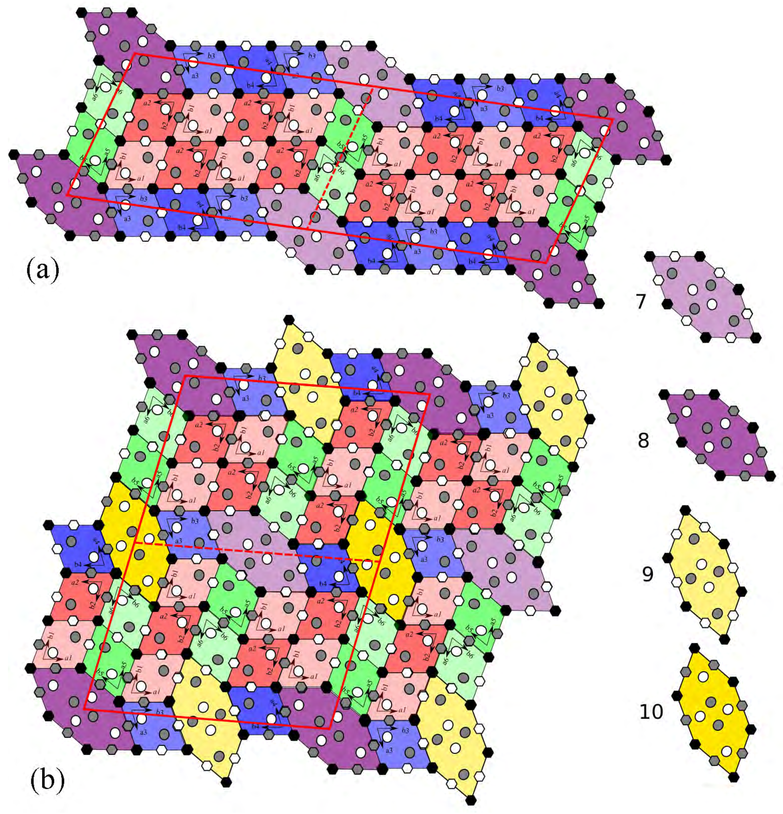
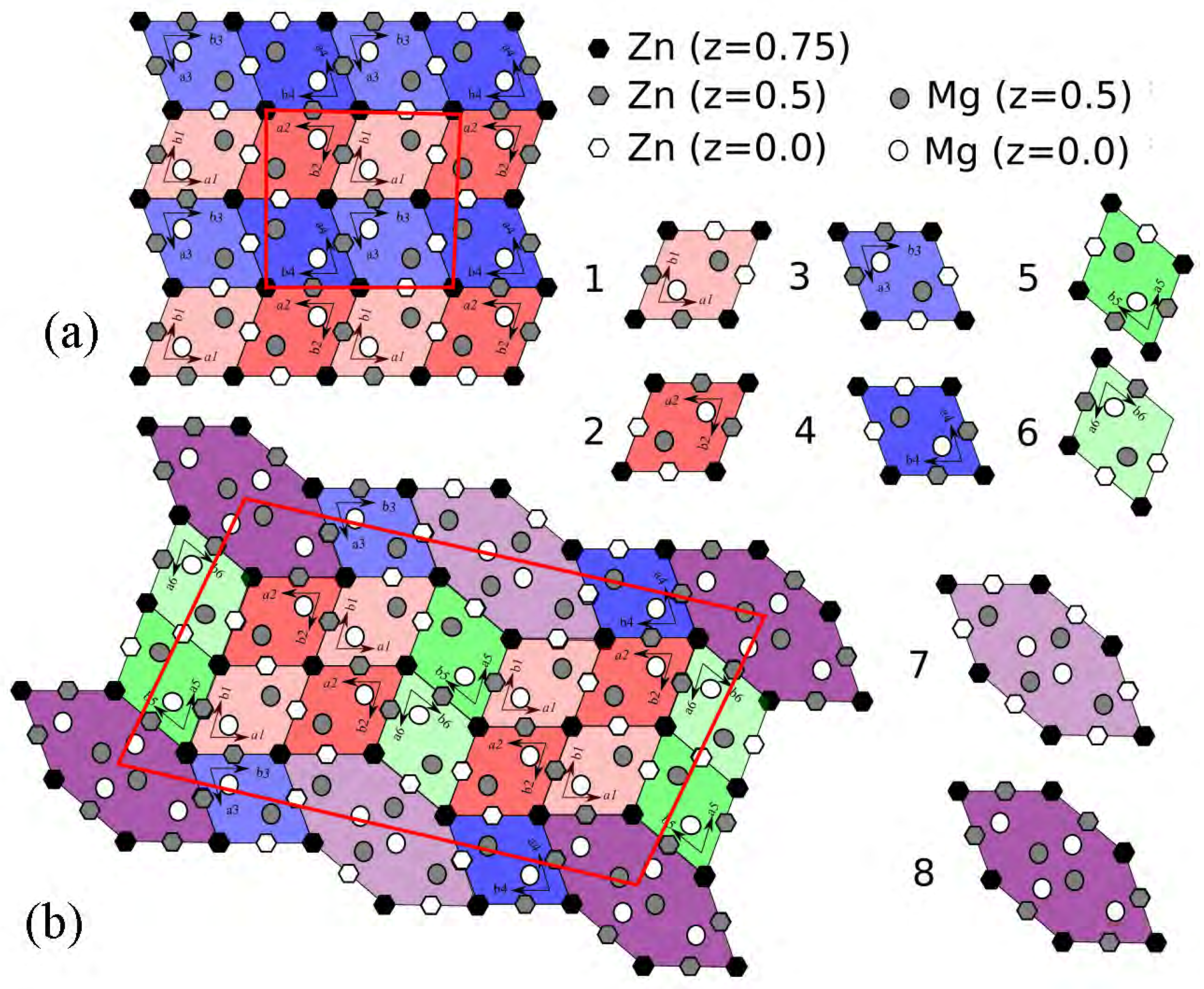
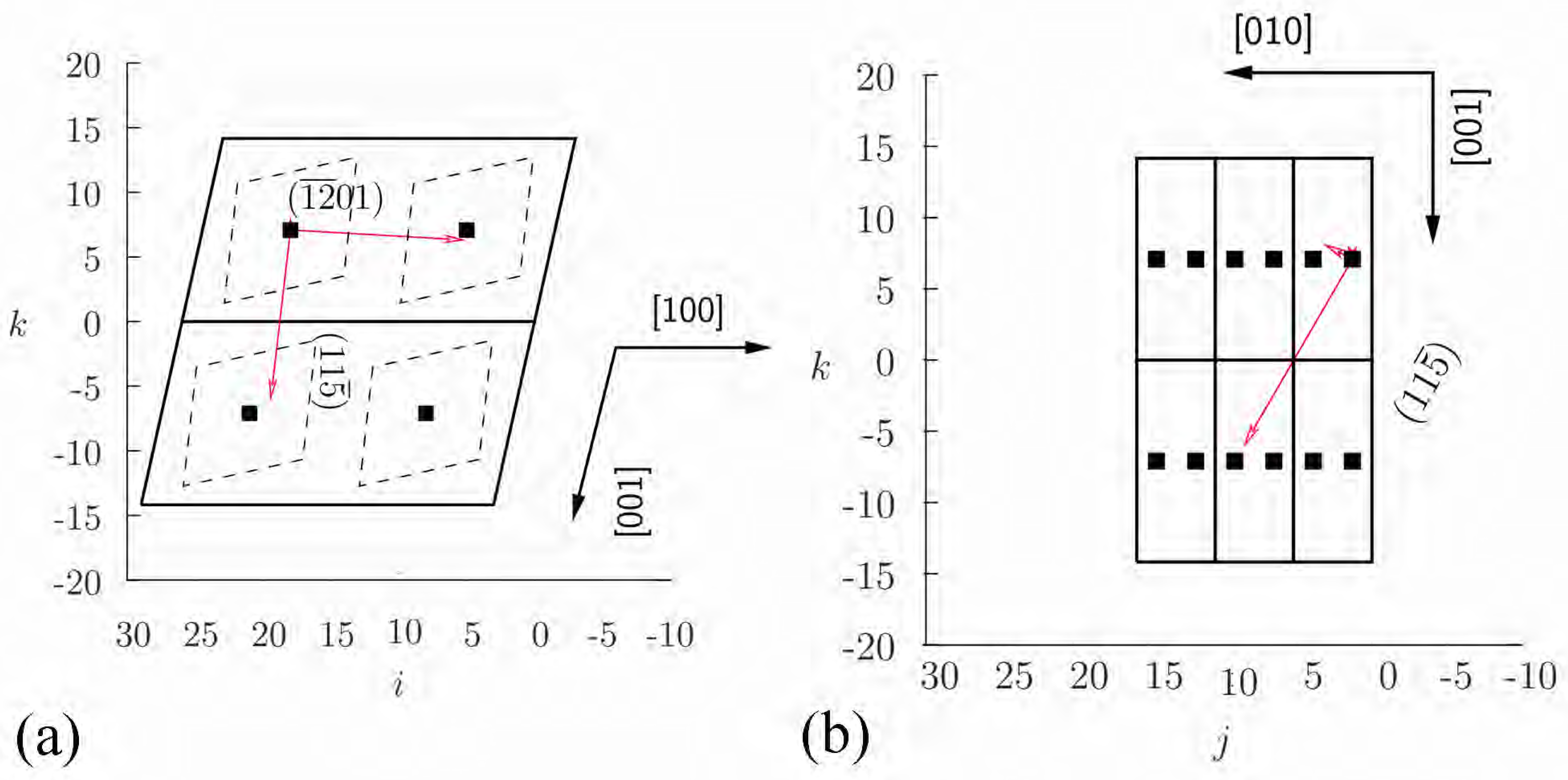
: Since this vector connects adjacent rhomboidal units, (Figure 10) the pseudo lattice parameter was taken as the ± 0.5 a Mg 4 Zn 7 . This has a magnitude of 12.48 Å, which is approximately 6 × d ( 12 ¯ 0 1 ) . (6 × d ( 12 ¯ 0 1 ) = 12.96 Å, within 3% of 0.5 a Mg 4 Zn 7 .)
  • The line between the centres of rhomboids lies parallel to [100] Mg 4 Zn 7 which is within 3 of the normal to ( 12 ¯ 0 1 ) .
  • ( 11 5 ¯ ) : The normal to the ( 11 5 ¯ ) plane lies close to the line connecting one rhomboidal unit with another with co-ordinates ± ( 1.5 b - c ) . This vector has magnitude 16.48 Å, equal to 6.495 × d ( 11 5 ¯ ) and the angle between the normal to the ( 11 5 ¯ ) plane is 4.9 .
  • (023): There is considerable distortion in this direction. The best match between the rhomboidal units and the twofold axis appears to be for the adjacent unit cell with ± c Mg 4 Zn 7 . This at a distance of 5.2 Å, or 2.27 times 6 × d ( 023 ) ; however, there is considerable angular distortion (also visible in the stereo projection).

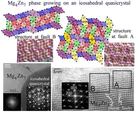
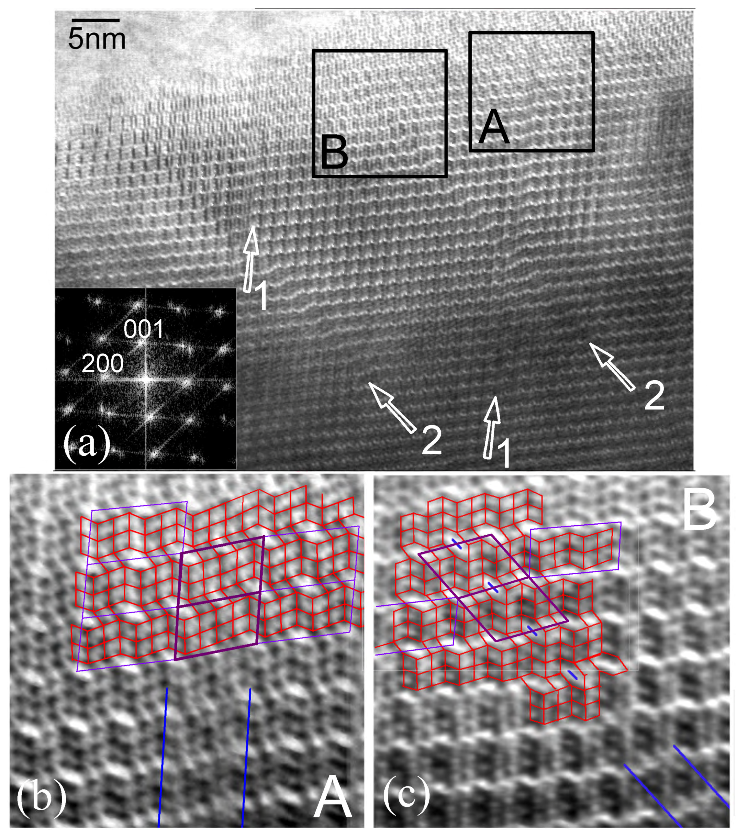
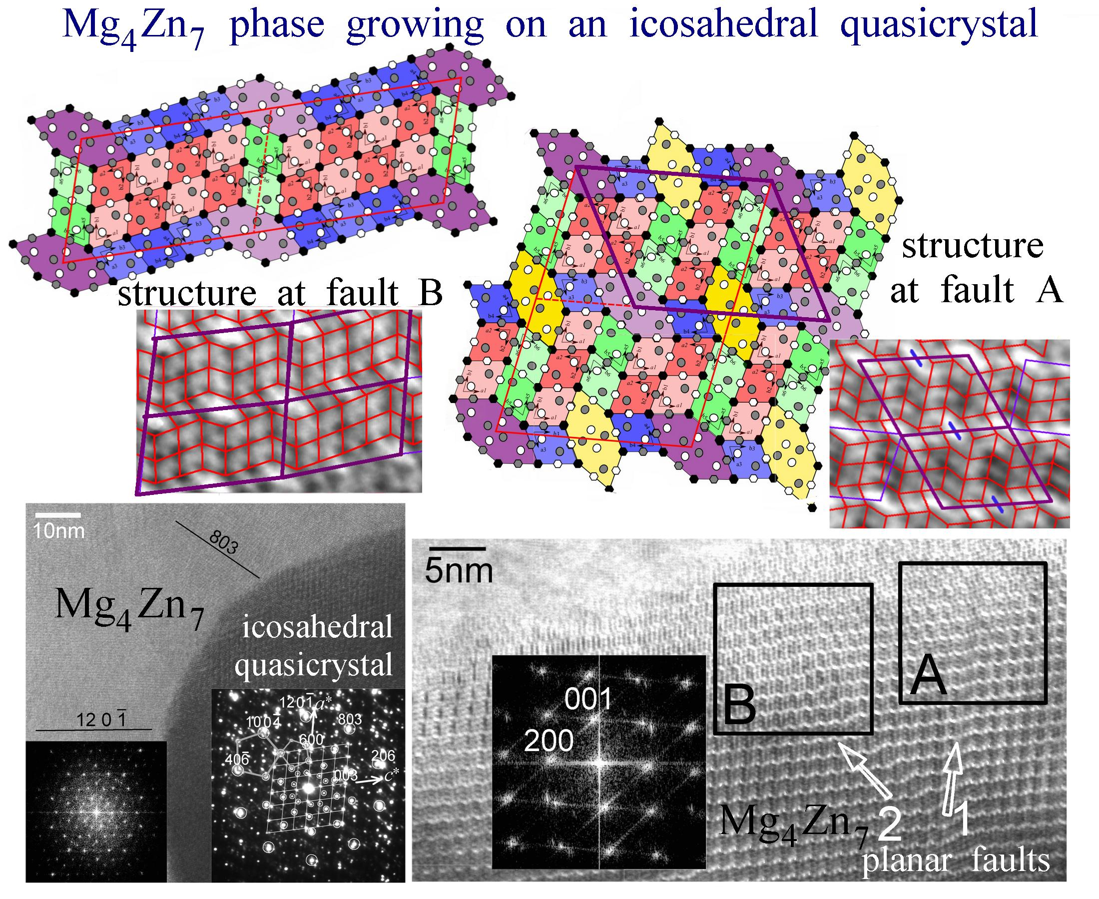
4.2. Structure at Planar Faults

The building blocks of the Mg 4 Zn 7 structure is a rhombus that connects the centers of icosahedral coordination units, Figure 1. Table 1 reports the various structures observed as variations of Mg 4 Zn 7 . The structures Tr(A) and Tr(B) reported by Rosalie et al. [23] are called transitional structures, referring to a transition to the MgZn 2 phase. Defects on plane ( 2 ¯ 01) can be understood from Rosalie et al. [26], where it is shown that an icosahedron can be defined at hexagonal sites of the Mg 4 Zn 7 unit cell, whose one of the twofold axis is along this plane. The structural units defined at these two kinds of planar faults are shown in Figure 11, and the lattice parameters determined are listed in Table 4. It can be observed in Figure 11b that there is one more orientation of hexagonal unit. The lattice parameter of fault B shows a monoclinic angle of 108 , whose acute complimentary angle is 72 (i.e., 2 π 5 ). An interesting question is about the stability of these structures. Similar modifications of the Mg 4 Zn 7 structure shown by us previously were tied to chemistry (local composition) [23]. In the present study, however, they seem to arise out of the lattice constraint of a periodic crystal growing on a quasiperiodic lattice. In this case, it is possible that these defects’ structures are necessary for the stability of the interface.
Here, we also note of a report of an icosahedral phase growing on a Mg 4 Zn 7 phase precipitate [35]. In this case, the icosahedral phase also shows streaked diffraction spots (in the direction of the growth, perpendicular to a fivefold plane). The icosahedral phase is reported to have grown in layers, possibly relating to the local chemistry.

5. Conclusions

Structure of a monoclinic Mg 4 Zn 7 phase growing on an icosahedral phase has been studied by transmission electron microscopy in a cast Mg-Zn-Y alloy. The lattice correspondence has been studied by electron diffraction. The structure of planar faults have been studied by high resolution microscopy. The following conclusions are drawn:
  • Mg 4 Zn 7 
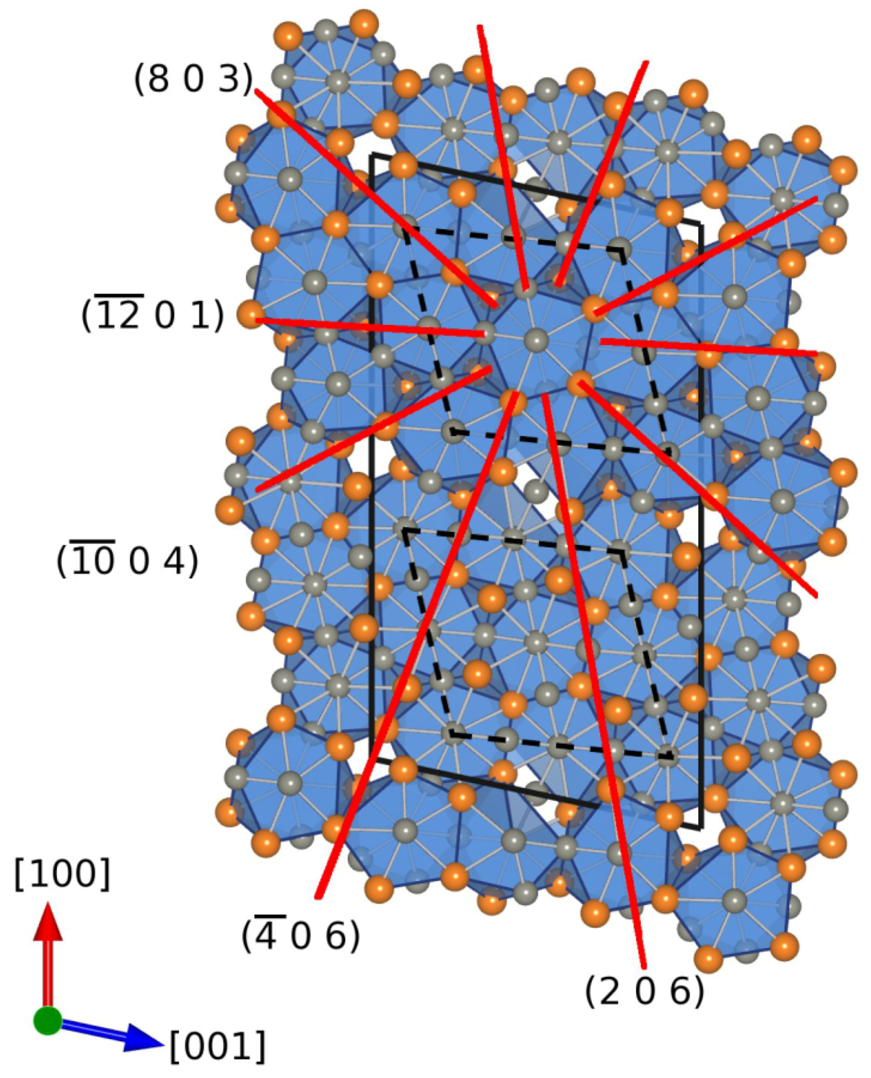
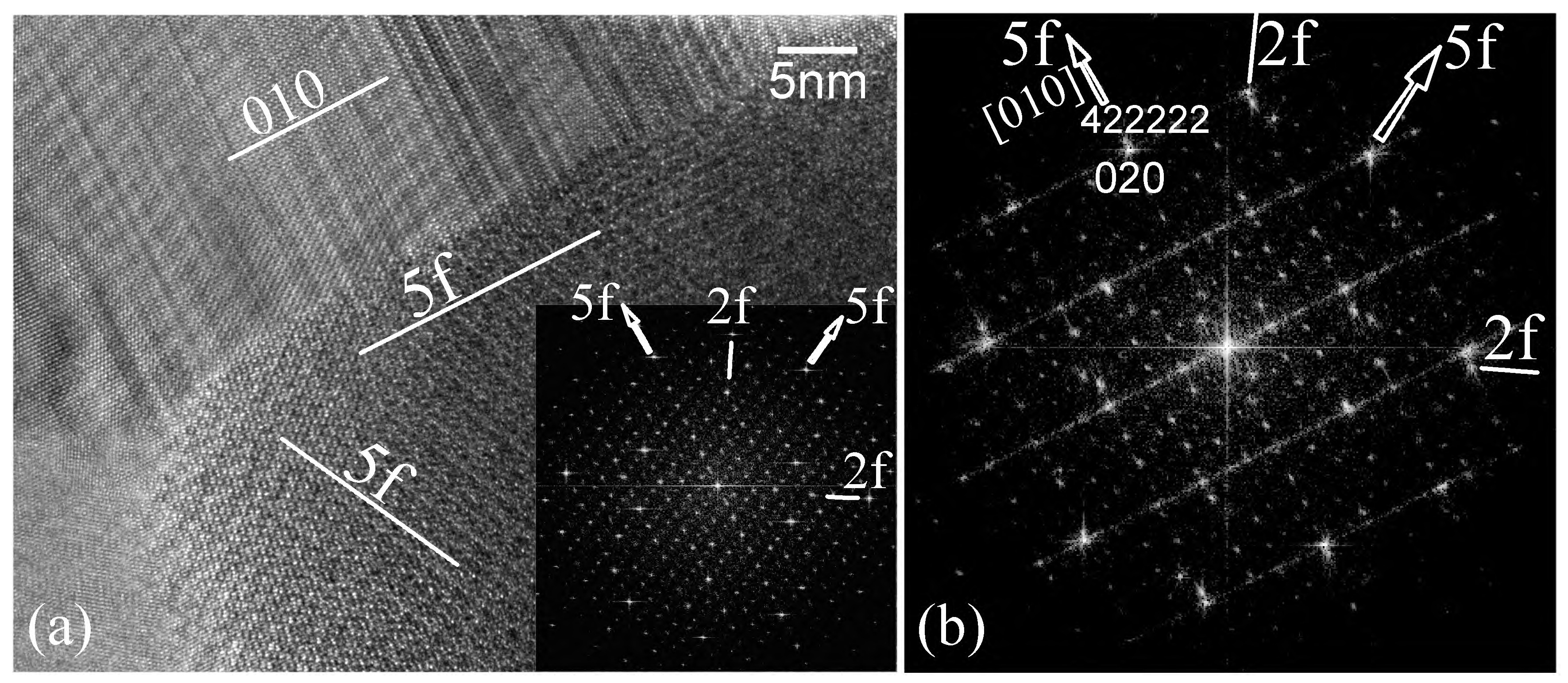
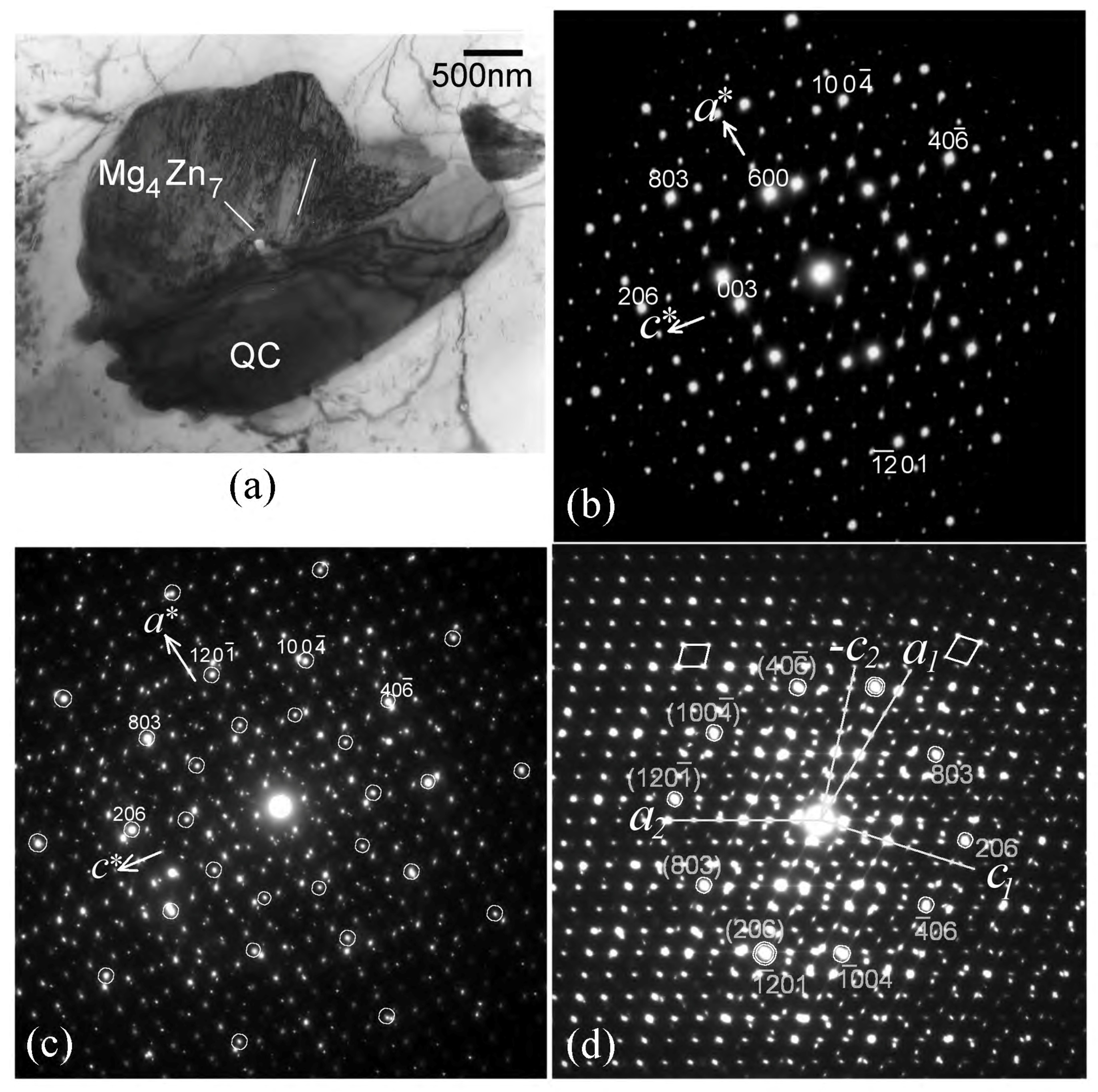
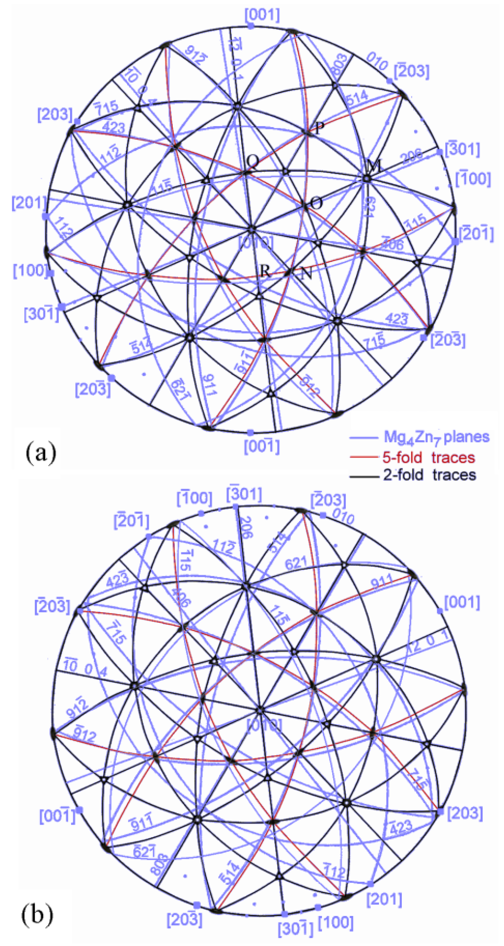
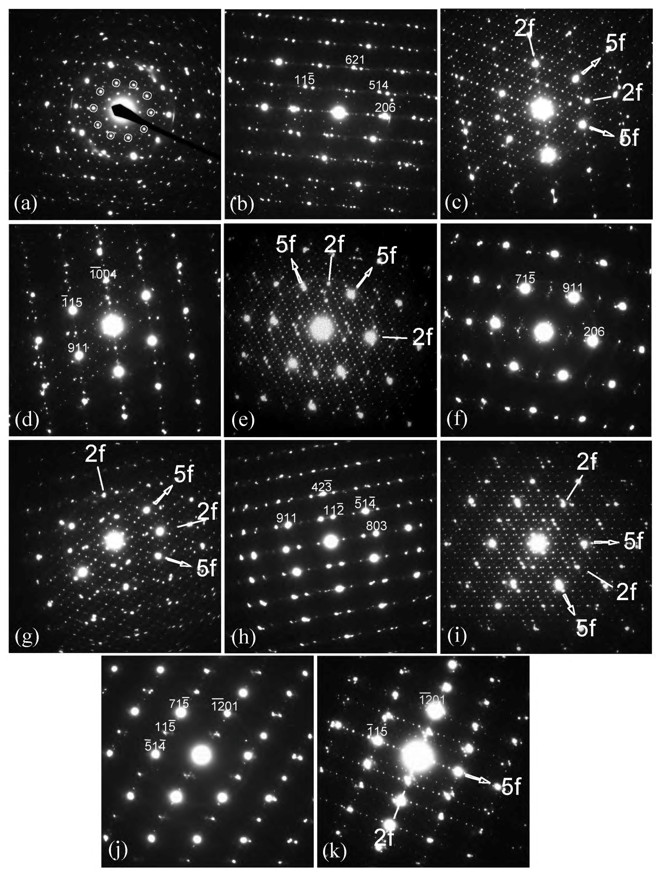
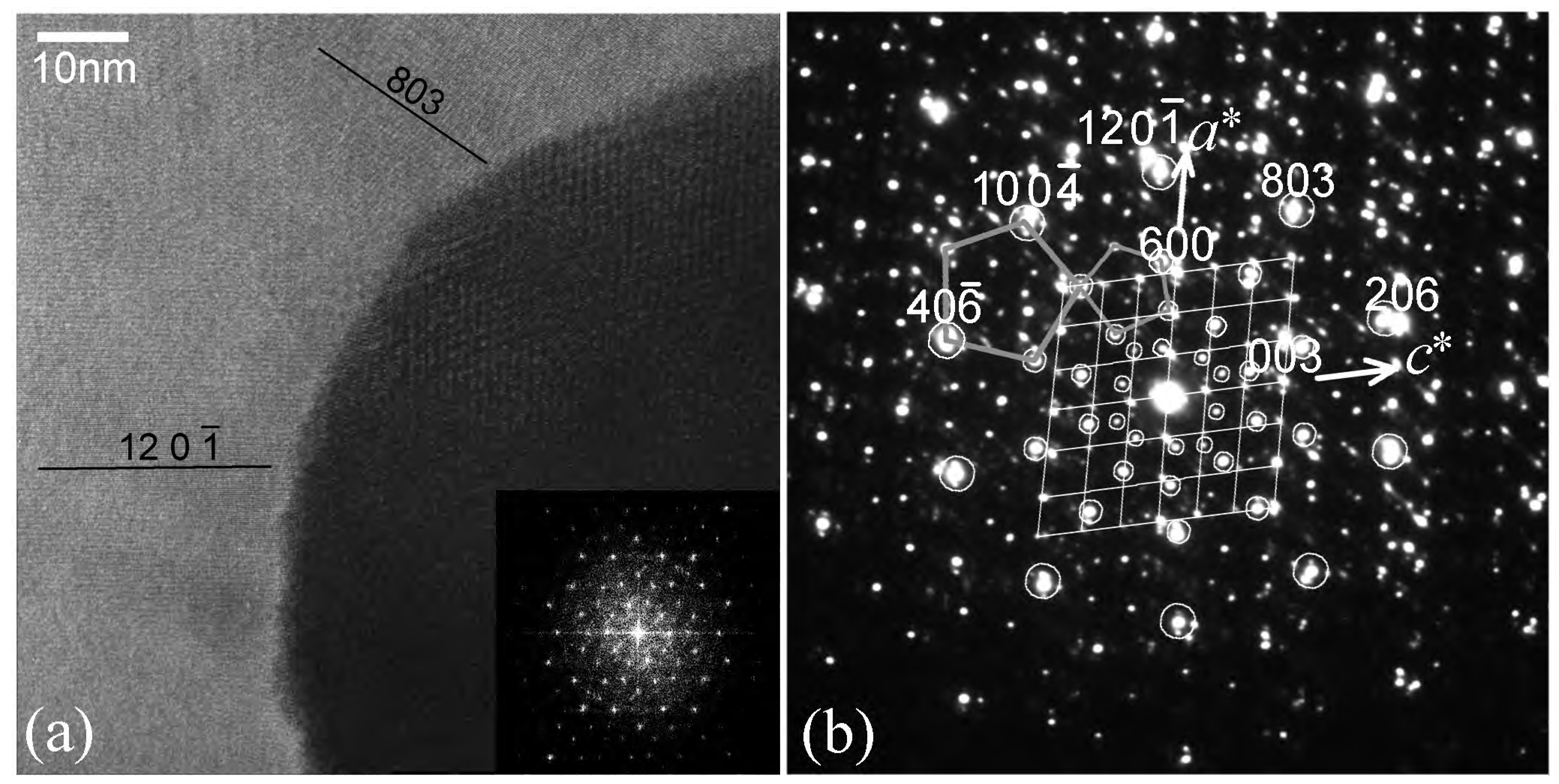
phase grows on an icosahedral phase with its [010] axis along a fivefold axis of the icosahedral phase, with orientation relationship [010] Mg 4 Zn 7 5 f , (803) Mg 4 Zn 7 { 2 f } . In the [010] Mg 4 Zn 7 zone axis diffraction pattern, pseudo-fivefold symmetry is generated by (803), (206), ( 4 ¯ 06), ( 10 ¯ 0 4) and (12 0 1 ¯ ) spots. These spot correspond to twofold symmetry vectors in the icosahedral lattice.
  • Five sets of three nearly-mutually orthogonal Mg 4 Zn 7 planes related to icosahedral twofold symmetry planes have been determined to define near-orthogonal cells. One such cell is defined by ( 12 ¯ 0 1)-(11 5 ¯ )-(023) set of planes.
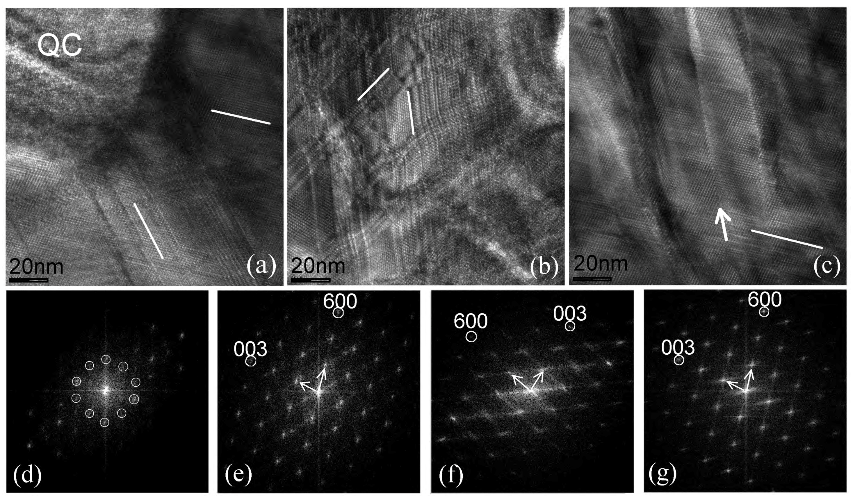
  • Due to incommensurable crystalline a-c plane with the fivefold icosahedral lattice planes, the Mg 4 Zn 7 lattice exhibited a high density of planar faults in this plane (parallel to its monoclinic axis). These faults were determined to be of two kinds, in {200} and { 2 ¯ 01} planes. Their structures were determined; the faults altered the unit cell to (i) a = 44.4, b = 5.24, c = 14.3 Å and β = 108 , and (ii) a = 32.0, b = 5.24, c = 22.7 Å and β = 103 .

Author Contributions

A.S. conceived, designed and performed the experiments; J.M.R. significantly contributed to analysis.

Acknowledgments

One of the authors (J.M.R.) gratefully acknowledges Japan Society for Promotion of Science for a fellowship to work at the National Institute for Materials Science. The authors thank Hidetoshi Somekawa for providing the alloy.

Conflicts of Interest

The authors declare no conflict of interest.

References

  1. Shechtman, D.; Blech, I.; Gratias, D.; Cahn, J.W. Metallic Phase with Long-Range Orientational Order and No Translational Symmetry. Phys. Rev. Lett. 1984, 53, 1951–1953. [Google Scholar] [CrossRef]
  2. Chattopadhyay, K.; Ranganathan, S.; Subbanna, G.N.; Thangaraj, N. Electron microscopy of quasi-crystals in rapidly solidified Al-14%Mn alloys. Scripta Metall. 1985, 19, 767–771. [Google Scholar] [CrossRef]
  3. Bendersky, L. Quasicrystal with One-Dimensional Translational Symmetry and a Tenfold Rotation Axis. Phys. Rev. Lett. 1985, 55, 1461–1463. [Google Scholar] [CrossRef] [PubMed]
  4. Schaefer, R.J.; Bendersky, L. Replacement of icosahedral Al-Mn by decagonal phase. Scripta Metall. 1986, 20, 745–750. [Google Scholar] [CrossRef]
  5. Thangaraj, N.; Subbanna, G.N.; Ranganathan, S.; Chattopadhyay, K. Electron microscopy and diffraction of icosahedral and decagonal quasicrystals in aluminium-manganese alloys. J. Microsc. 1987, 146, 287–302. [Google Scholar] [CrossRef]
  6. Hiraga, K.; Hirabayashi, M.; Inoue, A.; Masumoto, T. High resolution electron microscopy of AlMnSi icosahedral and AlMn decagonal quasicrystals. J. Microsc. 1987, 146, 245–260. [Google Scholar] [CrossRef]
  7. Levine, D.; Steinhardt, P.J. Quasicrystals: A New Class of Ordered Structures. Phys. Rev. Lett. 1984, 53, 2477–2480. [Google Scholar] [CrossRef]
  8. Levine, D.; Steinhardt, P.J. Quasicrystals. I. Definition and structure. Phys. Rev. B 1986, 34, 596–616. [Google Scholar] [CrossRef]
  9. Elser, V.; Henley, C.L. Crystal and Quasicrystal Structures in AlMnSi Alloys. Phys. Rev. Lett. 1985, 55, 2883–2886. [Google Scholar] [CrossRef] [PubMed]
  10. Ishihara, K. Periodic and Aperiodic Lattices. Mater. Sci. Forum 1987, 22–24, 223–230. [Google Scholar] [CrossRef]
  11. Luo, Z.P.; Zhang, S.Q.; Tang, Y.I.; Zhao, D. Quasicrystals in as-cast Mg-Zn-RE alloys. Scripta Metall. Mater. 1993, 28, 1513–1518. [Google Scholar] [CrossRef]
  12. Tsai, A.P.; Niikura, A.; Inoue, A.; Masumoto, T.; Nishida, Y.; Tsuda, K.; Tanaka, M. Highly ordered structure of icosahedral quasicrystals in Zn-Mg-RE (RE = rare earth metals) systems. Phil. Mag. Lett. 1994, 70, 169–175. [Google Scholar] [CrossRef]
  13. Sato, T.J.; Abe, E.; Tsai, A.P. Composition and stability of decagonal quasicrystals in the Zn-Mg-rare-earth systems. Philos. Mag. Lett. 1998, 77, 213–219. [Google Scholar] [CrossRef]
  14. Abe, E.; Sato, T.J. The structure of a Frank-Kasper decagonal quasicrystal in the Zn-Mg-Dy system: Comparison with the Al-Ni-Co system. Phil. Mag. Lett. 1998, 77, 205–211. [Google Scholar] [CrossRef]
  15. Yi, S.; Park, E.S.; Ok, J.B.; Kim, W.T.; Kim, D.H. Quasicrystals and related approximant phases in Mg-Zn-Y. Micron 2002, 33, 565–570. [Google Scholar] [CrossRef]
  16. Lebrun, N.; Stamou, A.; Baetzner, C.; Robinson, J.; Pisch, A. Magnesium-Yttrium-Zinc. In Ternary Alloys; Effenberg, G., Aldinger, F., Rogl, P., Eds.; MSI: Stuttgart, Germany, 2001; Volume 18, pp. 702–710. [Google Scholar]
  17. Clark, J.B.; Zabdyr, L.; Moser, Z. Mg-Zn (Magnesium-Zinc). In Phase Diagrams of Binary Magnesium Alloys; Nayeb-Hashemi, A.A., Clark, J.B., Eds.; ASM International: Materials Park, OH, USA, 1988; pp. 353–364. [Google Scholar]
  18. Friauf, J.B. The crystal structure of magnesium di-zincide. Phys. Rev. 1927, 29, 34–40. [Google Scholar] [CrossRef]
  19. Yarmolyuk, Y.P.; Kripyakevich, P.I.; Mel’nik, E.V. Crystal structure of the compound Mg4Zn7. Sov. Phys. Crystallogr. 1975, 20, 329–331. [Google Scholar]
  20. Yang, Q.B.; Kuo, K.H. A new description of pentagonal Frank-Kasper phases and a possible structural model of the icosahedral phase. Acta Cryst. A 1987, A43, 787–795. [Google Scholar] [CrossRef]
  21. Singh, A.; Tsai, A.P. Structural characteristics of β 1 precipitates in Mg-Zn-based alloys. Scripta Mater. 2007, 57, 941–944. [Google Scholar] [CrossRef]
  22. Baek, S.Y.; Lee, K.H.; Kim, T.S. HRTEM Study of Precipitation Behavior in Mg-6 wt%Zn-1 wt%Y Alloy. Korean J. Mater. Res. 2008, 18, 362–366. [Google Scholar] [CrossRef]
  23. Rosalie, J.; Somekawa, H.; Singh, A.; Mukai, T. Structural relationships among MgZn2 and Mg4Zn7 phases and transition structures in Mg-Zn-Y alloys. Philos. Mag. 2010, 90, 3355–3374. [Google Scholar] [CrossRef]
  24. Singh, A.; Rosalie, J.; Somekawa, H.; Mukai, T. The structure of β 1 precipitates in Mg-Zn-Y alloys. Phil. Mag. Lett. 2010, 90, 641–651. [Google Scholar] [CrossRef]
  25. Kim, W.J.; Hong, S.I.; Lee, K.H. Structural Characterization of Laves-Phase MgZn2 Precipitated in Mg-Zn-Y Alloy. Met. Mater. Int. 2010, 16, 171–174. [Google Scholar] [CrossRef]
  26. Rosalie, J.M.; Somekawa, H.; Singh, A.; Mukai, T. Orientation relationships between icosahedral clusters in hexagonal MgZn2 and monoclinic Mg4Zn7 phases in Mg-Zn(-Y) alloys. Phil. Mag. 2011, 91, 2634–2644. [Google Scholar] [CrossRef]
  27. Xie, Y.-P.; Wang, Z.-Y.; Hou, Z.F. The phase stability and elastic properties of MgZn2 and Mg4Zn7 in Mg-Zn alloys. Scripta Mater. 2013, 68, 495–498. [Google Scholar] [CrossRef]
  28. Li, X.-D.; Ma, H.-T.; Dai, Z.-H.; Qian, Y.-C.; Hu, L.-J.; Xie, Y.-P. First-principles study of coherent interfaces of Laves-phase MgZn2 and stability of thin MgZn2 layers in Mg-Zn alloys. J. Alloys. Comp. 2017, 696, 109–117. [Google Scholar] [CrossRef]
  29. Singh, A.; Somekawa, H.; Mukai, T. Microstructure and strength of extruded Mg-Zn-Ho alloys. 2017; in press. [Google Scholar]
  30. Elser, V. Indexing problems in quasicrystal diffraction. Phys. Rev. B 1985, 32, 4892–4898. [Google Scholar] [CrossRef]
  31. Momma, K.; Izumi, F. Other information about VESTA. VESTA 3 for three-dimensional visualization of crystal, volumetric and morphology data. J. Appl. Crystallogr. 2011, 44, 1272–1276. [Google Scholar] [CrossRef]
  32. Black, P.J. Structural relationships between intermetallic compounds. Acta Metall. 1956, 4, 172–179. [Google Scholar] [CrossRef]
  33. Henley, C.L. Crystals and quasicrystals in the aluminum-transition metal system. J. Non-Cryst. Solids 1985, 75, 91–96. [Google Scholar] [CrossRef]
  34. Kumar, V. An Atomistic Model for the Decagonal Phase of Al-Fe Alloy. Mater. Sci. Forum 1987, 22–24, 283–294. [Google Scholar] [CrossRef]
  35. Singh, A. Tailoring microstructure of Mg-Zn-Y alloys with quasicrystal and related phases for high mechanical strength. Sci. Technol. Adv. Mater. 2014, 15, 044803. [Google Scholar] [CrossRef] [PubMed]
Figure 1. Representation of the structures of (a) Laves phase MgZn 2 (projected along [110] axis with axes [1 1 ¯ 0] and [001] along horizontal and vertical directions, respectively) and (b) monoclinic Mg 4 Zn 7 phase (projected along the monoclinic [010] axis). Solid red lines outline the unit cell. Mg atoms are represented by circles and Zn atoms by hexagons; z-coordinates are indicated by shading (the co-ordinates are relative to the 5.2 Å b -lattice parameter of Mg 4 Zn 7 ). There are three pairs of differently oriented rhombic prisms required to make the structures (each type indicated by a different color in the figure, labelled 1–6). The members of each pair are distinguished by different shading intensities and differ in the z-coordinates of the Mg atoms and side-centered Zn atoms. Similarly, there is a pair of irregular hexagonal Zn-deficient sites (7–8), members of each pair again distinguished by the atom z-coordinates.
Crystals 08 00194 g001
Figure 2. A high resolution micrograph showing growth of monoclinic Mg 4 Zn 7 on an icosahedral phase in a Mg-6Zn-1Ho (at%) extruded at 230 C [29]. The icosahedral phase is in twofold zone axis orientation, as shown by the Fast Fourier Transform (FFT) inset in (a). The FFT in (b) shows that the monoclinic phase is oriented with its c-axis along a fivefold direction of the icosahedral phase. Fivefold and twofold symmetry reciprocal directions are marked.
Crystals 08 00194 g002
Figure 3. (a) coexisting icosahedral and Mg 4 Zn 7 phases in a Mg-Zn-Y alloy; (b) a diffraction pattern from the Mg 4 Zn 7 phase; (c) a composite diffraction pattern of icosahedral phase in a fivefold zone axis and the Mg 4 Zn 7 phase in [010] zone axis. Some spots from the icosahedral phase are marked by circles; (d) in one region [010], zone axis diffraction patterns in two orientations were observed, shown in this composite diffraction pattern. Indices for one variant are written with brackets, while, for the other orientation, without brackets.
Crystals 08 00194 g003
Figure 4. Stereograms for orientation relationship (a) OR1 and (b) OR2.
Crystals 08 00194 g004
Figure 5. Composite icosahedral phase- Mg 4 Zn 7 diffraction patterns and corresponding Mg 4 Zn 7 diffraction patterns from axes in the stereogram of Figure 4a marked (a,b) M, (c,d) N, (e,f) O, (g,h) P, (i,j) Q and (k) R. Fivefold (5f) and twofold (2f) symmetry reciprocal directions are marked in the icosahedral symmetry diffraction patterns.
Crystals 08 00194 g005
Figure 6. (a) interface between the icosahedral phase and the monoclinic phase. Planar defects seem to originate from the interface. Two main planes of defects are marked by white lines; (b) a high density of planar defects, mainly in two directions marked by two lines; (c) a set of planar faults (marked with a white line) and a wavy line of defect (marked by an arrow) in the monoclinic phase. FFT patterns from the icosahedral quasicrystal region (QC) and the monoclinic phase in (a) are shown in (d,e), respectively; (f) FFT pattern of image (b). (g) FFT pattern from image (c), which includes the defect marked by an arrow.
Crystals 08 00194 g006
Figure 7. Another high resolution micrograph showing interface between the icosahedral phase and the monoclinic phase. An FFT from the icosahedral phase is inset on the bottom right in (a). A composite diffraction pattern from the two phases is shown in (b). In this diffraction pattern, prominent icosahedral phase spots are marked by circles. Position of monoclinic phase spots are shown by a grid in the center.
Crystals 08 00194 g007
Figure 8. (a) a high resolution image of the monoclinic phase showing two kinds of planar defects marked 1 and 2 with arrows. The inset FFT indicates that these defects are on {200} and { 2 ¯ 01} planes. Regions marked A and B are shown in greater detail in (b,c), in each of which the planar region containing the lattice defect are marked with two parallel lines.
Crystals 08 00194 g008
Figure 9. Relationship between the monoclinic cell and planes normal to the monoclinic [010] axis. Unit cell: solid line, Rhomboidal units: dashed lines, and Planes: red lines.
Crystals 08 00194 g009
Figure 10. Relationship between the monoclinic cell and (a) planes normal to the monoclinic [010] axis and (b) in b c plane. Unit cell edges are shown by the bold, solid lines; the rhomboidal units are indicated by dashed lines. The normals to the pseudo-2f axes for variant one are shown by the red arrows. The filled squares show the centres of the rhomboidal units. Distances are shown in units of Angstroms.
Crystals 08 00194 g010
Figure 11. Atomic structures at planar defects of Mg 4 Zn 7 (a) defect A and (b) defect B. Solid red lines outline the unit cell; dashed red lines represent the asymmetric unit. Mg atoms are represented by circles and Zn atoms by hexagons. There is one more pair (than the regular structure shown in Figure 1) of irregular hexagonal Zn-deficient sites (9 and 10), members of each pair again distinguished by the atom z-coordinates.
Crystals 08 00194 g011
Table 1. Most intense diffraction peaks of Mg 4 Zn 7 phase, with experimental intensity values from powder diffraction pattern [19], as well as calculated intensities using program VESTA [31], and their correspondence to icosahedral reciprocal vectors (5f, 3f and 2f denote fivefold, threefold and twofold icosahedral reciprocal vectors, respectively. 5f is highlighted in bold).
Peak IndicesPlanar Spacing (Å)Intensity (%)Correspondence to Icosahedral Vector
ExperimentalCalculated
4 ¯ 2 32.22100712f, 3 f
2 0 62.2089672f
7 ¯ 1 52.24691002f, 5f
6 ¯ 2 12.24-162f, 3 f
12 ¯ 0 12.1654722f
1 ¯ 1 62.16-8
6 2 12.16-172f, 3 f
1 ¯ 1 24.2250342f, 3 f
5 1 42.3444582f, 5f
0 0 34.644360
9 ¯ 1 22.4933312f, 5f
1 ¯ 1 52.49-322f, 5f
9 1 12.3633492f, 5f
6 ¯ 2 32.103339
3 ¯ 1 14.3931412f
4 ¯ 0 62.3531352f
10 ¯ 0 42.3018282f
4 2 32.0815152f, 3 f
8 0 32.3914202f
0 2 02.62-85f
Table 2. Interplanar spacings for the strongly diffracting icosahedral twofold symmetry-related planes.
VariantPlaned (hkl)
1(1 1 5 ¯ )2.525
( 12 ¯ 0 1)2.159
(0 2 3)2.291
2(2 0 6)2.239
( 9 1 2 ¯ )2.491
( 6 ¯ 2 1)2.239
3( 10 ¯ 0 4)2.303
(1 1 1) *2.381
( 5 ¯ 1 4 ¯ )2.370
4( 4 ¯ 0 6)2.380
(9 1 1)2.374
( 6 2 ¯ 1)2.165
5(8 0 3)2.412
( 7 ¯ 1 5)2.255
( 4 2 3 ¯ )2.228
Table 3. Angle between principal vectors for each variant.
Variant 1 ( 11 5 ¯ ) ( 12 ¯ 0 1 ) (023)
( 11 5 ¯ ) 92.58590.066
( 12 ¯ 01 ) 91.66
Variant 2(206) ( 91 2 ¯ ) ( 6 ¯ 21 )
(206) 90.95892.4
( 91 2 ¯ ) 92.793
Variant 3 ( 10 ¯ 0 4 ) ( 111 ) ( 5 ¯ 1 4 ¯ )
( 10 ¯ 04 ) 89.39687.076
( 111 ) 87.722
Variant 4 ( 4 ¯ 06 ) (911) ( 6 2 ¯ 1 )
( 4 ¯ 06 ) 89.03586.696
( 911) 82.748
Variant 5(803) ( 7 ¯ 15 ) ( 42 3 ¯ )
(803) 90.34190.669
( 7 ¯ 15 ) 96.247
Table 4. Reported variations of Mg 4 Zn 7 structure.
StructureLattice ParametersComments
a, Åb, Åc, Å β ,
Mg 4 Zn 7 25.965.2414.48102.5[19]
Tr(A) Mg 64 Zn 118 25.965.2423.8999.4[23]
Tr(B) Mg 64 Zn 122 43.715.2414.48107.3[23]
fault A44.45.2414.3108present study
fault B32.05.2422.7103present study

