Article

Effects of Iodine Doping on Carrier Behavior at the Interface of Perovskite Crystals: Efficiency and Stability

1
School of Science, Jiangnan University, Wuxi 214122, China
2
School of Materials Science & Engineering, Beijing Institute of Technology, Beijing 100081, China
3
College of Engineering, Peking University, Beijing 100871, China
*
Author to whom correspondence should be addressed.
Crystals 2018, 8(5), 185; https://doi.org/10.3390/cryst8050185
Submission received: 22 March 2018 / Revised: 21 April 2018 / Accepted: 21 April 2018 / Published: 25 April 2018

Abstract

:
The interface related to the polycrystalline hybrid perovskite thin film plays an essential role in the resulting device performance. Iodine was employed as an additive to modify the interface between perovskite and spiro-OMeTAD hole transport layer. The oxidation ability of iodine significantly improved the efficiency of charge extraction for perovskite solar cells. It reveals that the Open Circuit Voltage (Voc) and Fill Factor (FF) of perovskite solar cells were improved substantially due to the dopant, which is mainly attributed to the interfacial improvement. It was found that the best efficiency of the devices was achieved when the dopant of iodine was in equivalent mole concentration with that of spiro-OMeTAD. Moreover, the long-term stability of the corresponding device was investigated.

1. Introduction

Organometal halide perovskite solar cells (PSCs) have attracted much attention because of their advantages such as high-power efficiency [1,2,3], flexibility [4,5,6], and long-term stability [7,8,9]. Compared with silicon solar cells [10,11,12], perovskite solar cells have simplified manufacture processing, and can be rapidly fabricated by spin-coating with precursor solutions of lead (II) iodide and methylamine hydroiodide (MAI). After only a few years of development, perovskite solar cells have reached a comparable efficiency to that of crystalline silicon solar cells [13]. To further improve the high efficiency, issues regarding crystallinity [14,15], film morphology [16,17], and grain size [18,19] have been widely investigated. The photon absorption [20] was a key purpose in those abovementioned investigations. Meanwhile, the charge extraction is equally important for perovskite crystals. Perovskite crystal surface and interfaces play an essential role in determining device performance, which includes different functional components such as the electron transport layer (ETL), hole transport layer (HTL), counter electrode, and so forth. In contrast to electrons, the transportation for holes within devices is challenging because of the heavier effective mass of holes [21] and the lack of HTLs with satisfactory hole conductivity. Moreover, carrier accumulation would be disastrous if carriers are not balanced in the photovoltaic devices [22]. Therefore, in the charge extraction step, the interfaces between the perovskite crystal and HTLs should be carefully studied with the emphasis on charge extraction and interface interactions [23]. To improve the hole conductivity in the organic HTL, oxidization is a feasible approach to increase the carrier concentration and thus the depletion length. However, the application of oxidant may deteriorate the perovskite crystals and its interface. Coincidentally, spiro-OMeTAD aging takes a long time in oxygen [24]. Considering HTL aging, we propose iodine as a dopant in the spiro-OMeTAD layer in order to increase the efficiency of charge extraction without damaging the polycrystalline perovskite thin films. Seok [25] recently found that additional iodide ions could decrease the concentration of deep-level defects in formamidinium-lead-halide-based perovskite solar cells. This research indicated that using the dopant of iodine was a feasible method for methylamine-lead-halide-based perovskite solar cells as well.

2. Experimental

2.1. Fabrication

The Indium Tin Oxides (ITO) substrates were cleaned with isopropanol, acetone, ethanol, and distilled water in a sonicator and then were blown with nitrogen gas. All substrates were sent into an ozonizer for a 20-min UV treatment. SnOx solution (15% in H2O, Alfa Aesar, Haverhill, MA, USA) were then spin-coated on substrates as the electron transport layer (ETL) and annealed at 150 °C for 30 min in ambient. The thickness was around 40 nm. Methylamine iodide (MAI, >99%, Sigma Aldrich, St. Louis, MO, USA) and lead (II) iodide (PbI2, 99%, Sigma Aldrich) were predissolved in N, N-dimethylformamide (DMF, >99%, Sigma Aldrich) as precursor solution before spin-coating process. After SnOx annealing, methylamine-lead(II)-iodide (MAPbI3) precursor solution was then spin-coated on ETL as an intrinsic layer at 3000 rpm for 20 s; 500 μL of diethyl ether (analytical reagent, Sinopharm Chemical Reagent Co., Ltd., Shanghai, China) was dripped (before end of the 14 s) on perovskite films during the spin-coating operation. Substrates were immediately moved to hot plate for 10 min annealing at 75 °C to exclude solvents. The thickness of perovskite film was around 300 nm. 2,2′,7,7′–tertrakis(N, N-dimethoxyphenylamine)-9,9′-spirobiflurorene (Spiro-OMeTAD, 99%, Sigma Aldrich) solution was prepared by dissolving 80 mg of spiro-OMeTAD, 30 μL of 4-tert-butylpyridine (TBP, 99.9%, Sigma Aldrich), and 35 μL of a stock solution of 260 mg/mL lithium bis(trifluoromethylsulfonyl)-imide (Li-TFSI, 99.9%, Sigma Aldrich) in acetonitrile (99.9%, Sigma Aldrich) in 1 mL of chlorobenzene (99.9%, Sigma Aldrich). The iodine (99.8%, Sigma Aldrich) was doped into the spiro-OMeTAD solution in different concentrations. The dopant was varied from 0 mg/mL to 15 mg/mL in a gradient of 3 mg/mL. Before the metal electrode evaporation, samples were sent into an oxygenated, sealed cabin for 12-h of aging. Finally, the 100-nm counter electrode was deposited by thermal evaporation of gold under a pressure of 5 × 10⁻⁵ Pa to form five functional cells. The effective area was 0.102 cm2.

2.2. Characterization

The X-ray diffraction (XRD) spectrum of the ITO/perovskite film was measured using a PANalytical X-ray diffractometer with Cu kα radiation at a scanning rate (2θ) of 3° min−1. The accelerating voltage and current were 40 kV and 40 mA, respectively. Ultraviolet/visible (UV/vis) absorption spectrum was recorded by a Hitachi (model UH4150) spectrophotometer at a rate of 0.5 nm/s. Photocurrent–voltage (JV) measurements for the perovskite solar cells were characterized under both dark and AM 1.5 G irradiation (100 mW/cm2) by using a xenon lamp simulator (Enlitech, model-SS-F7-3A, Kaohsiung City, Taiwan) after sample fabrication. The fluorescence (FL) and time-resolved photoluminescence were characterized by Oxford FLS 920 and FLS 980, respectively. Cross-sectional images were measured by field emission scanning electron microscope (FE-SEM, Hitachi S-4800FESEM, Hitachi, Tokyo, Japan) operated at 5 kV. The transient photovoltage and transient photocurrent measurements were carried out by a home-built system. The Nd:YAG laser irradiated with a 1064-nm pulse with 200-ns bandwidth and then generated 532-nm green light after passing through a second harmonic generation (SHG) crystal. The light spot was incident on the optical attenuator and then excited samples. Before the laser output, the laser respectively travels through a polarizer, a half-wave plate, and the shutter, generating a p-polarized pulse. The transient voltage and current were then traced and recorded by a Tektronix MDO 400 oscilloscope.

3. Results and Discussion

The employment of iodine aims to improve the carrier extraction efficiency and avoid other negative effects. XRD analysis, shown in Figure 1a, indicated that the hexagonal phase of the perovskite crystal was stable following doped HTL deposition. The perovskite thin film has strong diffraction patterns at 14.1°, and 28.3°, assigned to 110 and 220 of MAPbI3, respectively. We did not observe the diffraction peak often shown at 12.7° with perovskite, which belongs to excess PbI2. The XRD diffraction pattern strongly supports the crystal stability. Similar results were shown in Figure S1: the spiro-OMeTAD HTL as well as the dopant gathered and transferred extracted charge carriers without damaging perovskite crystal quality. The absorption spectrum was slightly changed in the wavelength range from 600 to 800 nm, indicating that the dopant has a small influence on the perovskite crystal as well. Meanwhile, spiro-OMeTAD was rapidly oxidized as shown in the absorption spectrum (Figure 1b). Commonly, spiro-OMeTAD [26] absorbs photons in the wavelength around 300–420 nm, and oxidized spiro-OMeTAD+ has a polaronic band at 500 nm. Hence, we zoomed into the absorption spectrum in the 350–550 nm and 730–800 nm regions for comparison. The comparison was summarized in Figure 2.
The tail bandgap was in accordance with the XRD patterns in the perovskite samples with spiro-OMeTAD on top. In Figure 2b, the cutoff wavelengths were all around 1.59 eV, without shifts, which also strongly supports the stability of the perovskite crystal. Interestingly, in the 400 to 500 nm range, the absorption intensity gradient was increased when the doping concentration was below 9 mg/mL, mainly attributed to the formation of spiro-OMeTAD+. According to Figure 3a, it was vital to achieve the optimum doping concentration of iodine in the layer of spiro-OMeTAD, because iodine has a strong oxidation effect [27] on both perovskite and hole transport material. According to experimental details, the mole concentration of spiro-OMeTAD was approximately 6.452 × 10⁻² mmol/mL. Meanwhile, with the gradient of the concentration of the iodine dopant increasing, the I* radicals were consequently increased from 0 mmol/mL to 2.362 × 10⁻² mmol/mL, 4.724 × 10⁻² mmol/mL, 7.086 × 10⁻² mmol/mL, 9.448 × 10⁻² mmol/mL, and 3.543 × 10⁻¹ mmol/mL, respectively. In comparison to the constant molar concentration of spiro-OMeTAD, iodine was fully reduced by spiro-OMeTAD initially. Once the concentration was over 9 mg/mL, polarons [27] were formed after reaction with I2 as the excessive oxidant. Herein, the absorption intensity decreased (in Figure S2) after dopant concentration was over 9 mg/mL due to the photobleaching effect.
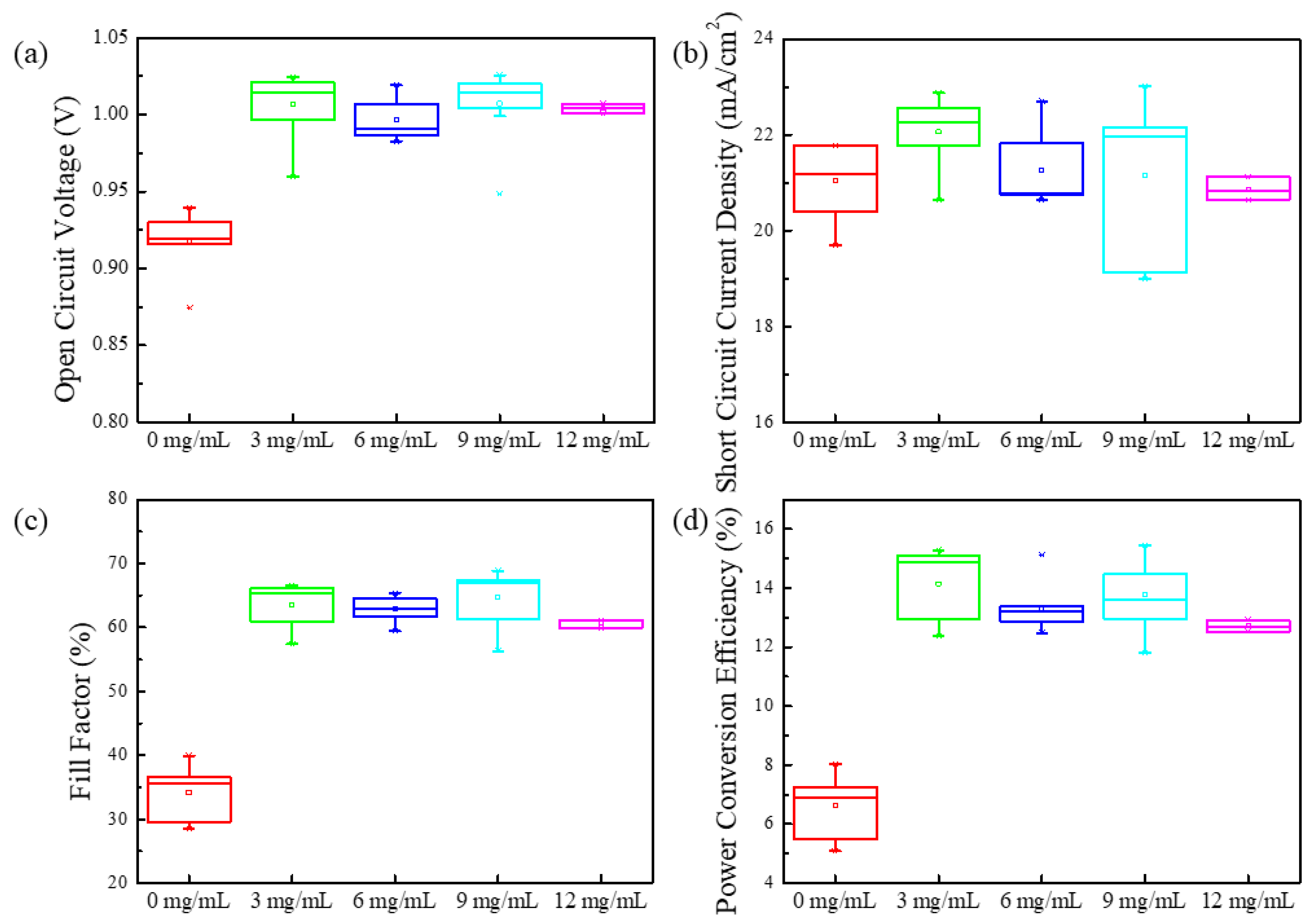
The photovoltaic properties of the MAPbI3 PSCs were sequentially characterized under solar simulator after counter electrode evaporation. It is worth mentioning that the silver electrode is not suitable for iodine dopant-based HTLs due to silver iodide (AgI) formation, according to our records in Figure S3. Thermal evaporation is a homogeneous deposition process; however, we have observed a gradient variation of rough surfaces after silver evaporation. Obviously, the quality of electrode morphology relied on the overweighting of iodine. To exclude the formation of AgI, we applied gold as the counter electrode material for the PSCs. The photovoltaic parameters were summarized and are shown in Figure 3. It can be seen that the Voc was immediately increased from 0.92 V (average) to over 1 V due to spiro-OMeTAD+ formation. According to the definition, the Voc is related to both light-generated current and saturation current [28], as shown by Equation (1):
V oc = n k T q ln ( I L I 0 + 1 )
where n is the ideality factor, T is the absolute temperature, IL is the photo-generated current, Isc is the short-circuit current, and I0 is the reverse saturation current. In the open-circuit condition, most charges remained in excited states and decayed to ground states through a nongeminate recombination. As we have described, the dopant has slight impacts on perovskite crystals, and the photo-generated currents were approximately close to each other. As a result, the Voc depends on the saturation current. JV measurements in the dark condition are summarized in Figure S4 (Supplementary Materials). It was found that the Is was decreased from 100 μA to only 14 μA once the iodine was doped into the HTL. Meanwhile, under the forward bias condition, the depletion zone was extended because of spiro-OMeTAD+ formation. As a result, the threshold voltage was increased from 1.47 V to 1.76 V. Hence, the Voc was immediately increased when the dopant was employed in the HTL.
The spiro-OMeTAD+ was instantly formed by the iodine dopant, leading to an improved charge extraction, leading to a FF promotion. Meanwhile, it was found that the grain boundaries were improved as well (Figure S5). The perovskite crystal grain grew larger in low dopant concentration, which contributed to the charge extraction as well. In comparison to the pristine 35%, the FF was dramatically increased to over 60%. However, though the charge extraction was improved, the charge density was relatively stable because of the limitation of photon absorption. Furthermore, apparently, the charge transport remained stable since the thicknesses of all layers were the same, as described in the Experimental section. Hence, the short-circuit current density (Jsc) remained stable, indicating that the charge density was rarely decreased after iodine doping. All these parameters contributed to the Power Conversion Efficiency (PCE). Although the average and highest PCE of a single channel was from the group of 3 mg/mL, we believe that the group of 6 mg/mL was better for the practical application because its PCE was smaller in the dispersion ratio compared with others. Also, we provided photovoltaic properties of PSCs with silver electrodes in Figure S6. In low dopant concentration, the FF suddenly increased to 60% because of the interfacial improvement. It is clear to see that the highest PCE was from the group of 6 mg/mL, corresponding to the molar ratio as we have mentioned. In the condition of dopant concentration of 6 mg/mL, most spiro-OMeTAD can be oxidized into spiro-OMeTAD+ without the introduction of iodine impurity. However, once the dopant concentration was over 9 mg/mL, excess iodine remained in the HTL, leading to the short-circuit current collapse. These results were in accordance with Figure S6; both indicated that high concentration of iodine is unsuitable for HTLs and PSCs.
The interfacial charge extraction was characterized by the time-resolved photoluminescence based on samples of perovskite film and perovskite/HTL dual films. The results were summarized in Figure S1. The intersystem conversion rate was rapidly increased by at least one order of magnitude once the HTL was spin-coated onto the perovskite film. Simultaneously, the singlet transition was around 2 ns, independent of the HTL contact. Note that the time-resolved photoluminescence and fluorescence have invariant radiation efficiency and peak positions, indicating that the oxidant has a negligible influence on perovskite crystals.
Further transient photovoltage (TPV) and transient photocurrent (TPC) investigations were carried out to verify the interfacial interactions as drawn in Figure S8. The laser was integrated with the polarizers and a half-wave plate inside. Conventionally, the laser was perpendicularly injected into PSCs with p-polarized light, triggering the -electron photoexcitation perpendicular to the interface, while other information such as the interfacial interactions was eliminated. We modified the TPV/TPC setups with a home-built sample holder so that the PSC could rotate 45 degrees along with the tangential direction. Once the sample was deviated from its original position, the excited state of perovskite crystal would be polarized across the interface perpendicular with the Poynting vector. Hence, the interfacial interactions can be traced by comparing with different angles, as shown in Figure 4.
The charge dynamics confirmed that iodine doping has a positive effect on the interfacial charge transfer of perovskite crystals. The excited polarons were polarized across the interface once the electric field of light was shifted 45°, as we assumed. As plotted in Figure 4, the excited electron transfer was 5 μs faster than instantly after the sample was tilted, due to the interfacial interactions. Meanwhile, the iodine doping has a slight influence on perovskite crystals, as we have reiterated. The nongeminate recombination then plays a dominant role in the open-circuit condition. The detrapping rate constant used of 2.57 × 10⁷ s−1 qualitatively reproduces the current tail after light-off, confirming that charges in perovskite crystal are rapidly detrapped. The current intensity and trapping rates were slightly changed compared with the perpendicular incident condition. Although the transient photovoltage was lower at 45° of incidence angle, the charge extraction remained stable with a constant trapping rate of 9.48 × 10⁴ s−1 in the short-circuit condition.
However, the long-term stability was unsatisfactory, compared with dopant-free samples. After one-week exposure in ambient air, PSCs with doped HTLs lost power generation ability, while PSCs with pure spiro-OMeTAD HTLs maintained stability in PCE. One reason [29] is that the I diffused to the anode, leading to a light-induced reactivity of the gold iodide; a new possible degradation mechanism in PSCs. The formation of MA2Au2I6 blocked charge extraction, and then the PCE was dramatically decreased after long-term exposure in air. After one-week exposure in ambient air, samples were characterized by XRD measurements; the XRD patterns are shown in Figure 5. It can be seen that a split peak appeared close to 14.1° once the iodine was doped into the HTL. The result was in accordance with the formation of MA2Au2I6, as we have mentioned [29]. Meanwhile, an additional peak emerged at 6.79° after one week in air. This peak was compared with related research [30]. A new phase of the Pb3I8 intermediate was formed due to the perovskite decomposition. The excess iodine played an important role in the perovskite decomposition since the dopant-free sample remained in the tetragonal phase. As a result, in order to avoid the ion diffusion, an additional buffer layer such as polymethyl methacrylate (PMMA) is essential for further studies of long-term stability based on this type of structure.

4. Conclusions

In this article, iodine effects on the perovskite crystal and the relevant device are investigated. It was found that when it is applied in an HTL, the oxidation time for the HTL can be significantly decreased. The experimental results found that iodine has no substantial impacts on crystal quality or the perovskite optical bandgap. The PSC performance was best when the molar ratio of dopant and spiro-OMeTAD was equal; that is, in equivalent mole concentration. The improvement was mainly benefited from Voc and FF enhancement, possibly due to the charge extraction enhancement. However, iodine doping devices exhibit decreased stability. These findings can be used to guide the design of other optoelectronic devices such as light-emitting diodes and lasers, which have recently involved hybrid perovskite materials.

Supplementary Materials

The following are available online at https://www.mdpi.com/2073-4352/8/5/185/s1, Figure S1: The fluorescence spectrum (a) and time-resolve photoluminescence spectra (b), Figure S2: absorption spectra of perovskite films with oxidized spiro-OMeTAD layers when the dopant was over 9 mg/mL, Figure S3: Rough morphology of sliver electrode with increasing iodine doping, Figure S4: Dark current of perovskite solar cells after the electrode evaporation, Figure S5: cross-section images of perovskite samples with doped HTL, the HTLs were doped with various concentration of iodine, Figure S6: photovoltaic parameters of PSCs evaporated with sliver electrode, Figure S7: Photovoltaic parameters of PSCs evaporated with gold electrodes. All samples were characterized after 48 h oxygen aging in sealed cabin, Figure S8: Schematic figure of TPV/TPC setups, Table S1: Lifetime extracted from Figure S1, where the t1 was the lifetime of radiative de-excitation and t2 was the time of delayed fluorescence.

Author Contributions

H.Z. and Q.C. conceived and designed the experiments; G.L. performed and analyzed the experiments; L.L. conceived the transient experiments and contributed analysis; X.N. contributed to the device fabrication and characterization. G.L. and Q.C. wrote the paper.

Acknowledgments

This work is supported by the Fundamental Research Funds for the Central Universities (Grant No. JUSRP11834). We sincerely thank Enli technology for offering the steady-state solar simulator.

Conflicts of Interest

The authors declare no conflict of interest.

References

  1. Zhou, H.; Chen, Q.; Li, G.; Luo, S.; Song, T.B.; Duan, H.S.; Hong, Z.; You, J.; Liu, Y.; Yang, Y. Interface engineering of highly efficient perovskite solar cells. Science 2014, 345, 542–546. [Google Scholar] [CrossRef] [PubMed]
  2. Sun, W.; Li, Y.; Xiao, Y.; Zhao, Z.; Ye, S.; Rao, H.; Ting, H.; Bian, Z.; Xiao, L.; Huang, C.; et al. An ammonia modified PEDOT: PSS for interfacial engineering in inverted planar perovskite solar cells. Org. Electron. 2017, 46, 22–27. [Google Scholar] [CrossRef]
  3. Burschka, J.; Nazeeruddin, M.K.; Gratzel, M. Sequential deposition as a route to high performance perovskite-sensitized solar cells. Nature 2013, 499, 316–319. [Google Scholar] [CrossRef] [PubMed]
  4. Heo, J.H.; Shin, D.H.; Jang, M.H.; Lee, M.L.; Kang, M.G.; Im, S.H. Highly flexible, high-performance perovskite solar cells with adhesion promoted AuCl3-doped graphene electrodes. J. Mater. Chem. A 2017, 5, 21146–21152. [Google Scholar] [CrossRef]
  5. Wang, Z.; Peng, L.; Lin, Z.; Ni, J.; Yi, P.; Lai, X.; He, X.; Lei, Z. Flexible semiconductor technologies with nanohole-provided high area coverages and their application in plasmonic-enhanced thin film photovoltaics. Sci. Rep. 2017, 7, 13155. [Google Scholar] [CrossRef] [PubMed]
  6. Chen, L.; Xie, X.; Liu, Z.; Lee, E.C. A transparent poly(3,4-ethylenedioxylenethiophene): Poly (styrene sulfonate) cathode for low temperature processed, metal-oxide free perovskite solar cells. J. Mater. Chem. A 2017, 5, 6974–6980. [Google Scholar] [CrossRef]
  7. Qiao, B.; Song, P.; Cao, J.; Zhao, S.; Shen, Z.; Gao, D.; Liang, Z.; Xu, Z.; Song, D.; Xu, X. Water-resistant, monodispersed and stably luminescent CsPbBr3/CsPb2Br5 core-shell-like structure lead halide perovskite nanocrystals. Nanotechnology 2017, 28, 445602. [Google Scholar] [CrossRef] [PubMed]
  8. Hou, X.; Huang, S.; Ou-Yang, W.; Pan, L.; Sun, Z.; Chen, X. Constructing efficient and stable perovskite solar cells via interconnecting perovskite grains. ACS Appl. Mater. Interfaces 2017, 9, 35200–35208. [Google Scholar] [CrossRef] [PubMed]
  9. Shukla, S.; Shukla, S.; Haur, L.J.; Dintakurti, S.S.; Han, G.; Priyadarshi, A.; Baikie, T.; Mhaisalkar, S.G.; Mathews, N. Effect of formamidinium/Cesium substitution and PbI2 on the long-term stability of triple-cation perovskites. ChemSusChem 2017, 10, 3804–3809. [Google Scholar] [CrossRef] [PubMed]
  10. Moumni, B.; Jaballah, A.B. Correlation between oxidant concentrations, morphological aspects and etching kinetics of silicon nanowires during sliver-assist electroless etching. Appl. Surf. Sci. 2017, 425, 1–7. [Google Scholar] [CrossRef]
  11. Jin, J.; Shen, H.; Zheng, P.; Chan, K.S.; Zhang, X.; Jin, H. >20.5% diamond wire sawn multicrystalline silicon solar cells with maskless inverted pyramid like texturing. IEEE J. Photovolt. 2017, 7, 1264–1269. [Google Scholar] [CrossRef]
  12. Dullweber, T.; Hannebauer, H.; Dorn, S.; Schimanke, S.; Merkle, A.; Hampe, C.; Brendel, R. Emitter saturation current densities of 22fA/cm2 applied to industrial PERC solar cells approaching 22% conversion efficiency. Prog. Photovolt. 2017, 25, 509–514. [Google Scholar] [CrossRef]
  13. Green, M.A.; Emery, K.; Hishikawa, Y.; Warta, W. Solar cell efficiency tables (version 51). Prog. Photovolt. 2017. [Google Scholar] [CrossRef]
  14. Chen, Q.; Zhou, H.; Hong, Z.; Luo, S.; Duan, H.S.; Wang, H.H.; Liu, Y.; Li, G.; Yang, Y. Planar heterojunction perovskite solar cells via vapor-assisted solution process. J. Am. Chem. Soc. 2014, 136, 622–625. [Google Scholar] [CrossRef] [PubMed]
  15. Liu, M.; Johnston, M.B.; Snaith, H.J. Efficient planar heterojunction perovskite solar cells by vapour deposition. Nature 2013, 501, 395–398. [Google Scholar] [CrossRef] [PubMed]
  16. Conings, B.; Baeten, L.; De Dobbelaere, C.; D’Haen, J.; Manca, J.; Boyen, H.G. Perovskite-based hybrid solar cells exceeding 10% efficiency with high reproducibility using a thin film sandwich approach. Adv. Mater. 2014, 26, 2041–2046. [Google Scholar] [CrossRef] [PubMed]
  17. Saliba, M.; Tan, K.W.; Sai, H.; Moore, D.T.; Scott, T.; Zhang, W.; Estroff, L.A.; Wiesner, U.; Snaith, H.J. Influence of thermal processing protocol upon the crystallization and photovoltaic performance of organic-inorganic lead trihalide perovskites. J. Phys. Chem. C 2014, 118, 17171–17177. [Google Scholar] [CrossRef]
  18. Xiao, M.; Huang, F.; Huang, W.; Dkhissi, Y.; Zhu, Y.; Etheridge, J.; Gray-Weale, A.; Bach, U.; Cheng, Y.B.; Spiccia, L. A fast deposition-crystallization procedure for highly efficient lead iodide perovskite thin-film solar cells. Angew. Chem. 2014, 126, 10056–10061. [Google Scholar] [CrossRef]
  19. Jeng, J.Y.; Chiang, Y.F.; Lee, M.H.; Peng, S.R.; Guo, T.F.; Chen, P.; Wen, T.C. CH3NH3PbI3 perovskite/fullerene planar heterojunction hybrid solar cells. Adv. Mater. 2013, 25, 3727–3732. [Google Scholar] [CrossRef] [PubMed]
  20. Da, Y.; Xuan, Y.M.; Li, Q. Quantifying energy losses in planar perovskite solar cells. Sol. Energy Mater. Sol. Cells 2017, 174, 206–213. [Google Scholar] [CrossRef]
  21. Si, H.; Liao, Q.; Zhang, Z.; Li, Y.; Yang, X.; Zhang, G.; Kang, Z.; Zhang, Y. An innovative design of perovskite solar cells with Al2O3 inserting at ZnO/perovskite interface for improving the performance and stability. Nano Energy 2016, 22, 223–231. [Google Scholar] [CrossRef]
  22. Zheng, K.; Žídek, K.; Abdellah, M.; Chen, J.; Chábera, P.; Zhang, W.; Al-Marri, M.J.; Pullerits, T. High excitation intensity opens a new trapping channel in organic-inorganic hybrid perovskite nanoparticles. ACS Energy Lett. 2016, 1, 1154–1161. [Google Scholar] [CrossRef]
  23. Sun, X.; Ji, L.Y.; Chen, W.W.; Guo, X.; Wang, H.H.; Lei, M.; Wang, Q.; Li, Y.F. Halide anion-fullerene pi noncovalent interactions: N-doping and a halide anion migration mechanism in p-i-n perovskite solar cells. J. Mater. Chem. A 2017, 5, 20720–20728. [Google Scholar] [CrossRef]
  24. Li, L.; Liu, N.; Xu, Z.; Chen, Q.; Wang, X.; Zhou, H. Precise Composition Tailoring of Mixed-Cation Hybrid Perovskites for Efficient Solar Cells by Mixture Design Methods. ACS Nano 2017, 11, 8804–8813. [Google Scholar] [CrossRef] [PubMed]
  25. Yang, W.S.; Park, B.W.; Seok, S.I. Iodine management in formamidinium-ldea-halide-based perovskite layers for efficient solar cells. Science 2017, 356, 1376–1379. [Google Scholar] [CrossRef] [PubMed]
  26. Carrillo, J.; Guerrero, A.; Rahimnejad, S.; Almora, O.; Zarazua, I.; Mas-Marza, E.; Bisquert, J.; Garcia-Belmonte, G. Ionic reactivity at contacts and aging of methylammonium lead triiodode perovskite solar cells. Adv. Energy Mater. 2016, 6, 1502246. [Google Scholar] [CrossRef]
  27. Tsai, H.; Nie, W.; Cheruku, P.; Mack, N.H.; Xu, P.; Gupta, G.; Mohite, A.D.; Wang, H.L. Optimizing composition and morphology for large-grain perovskite solar cells, via chemical control. Chem. Mater. 2015, 27, 5570–5576. [Google Scholar] [CrossRef]
  28. Park, I.J.; Seo, S.; Park, M.A.; Lee, S.; Kim, D.H.; Zhu, K.; Shin, H.; Kim, J.Y. Effect of rubidium incorporation on the structural, electrical, and photovoltaic properties of Methylammonium lead iodide-based perovskite solar cells. ACS Appl. Mater. Interfaces 2017, 9, 41898–41905. [Google Scholar] [CrossRef] [PubMed]
  29. Shlenskaya, N.N.; Belich, N.A.; Grätzel, M.; Goodilin, E.A.; Tarasov, A.B. Light-induced reactivity of gold and hybrid perovskite as a new possible degradation mechanism in perovskite solar cells. J. Mater. Chem. A 2018, 6, 1780–1786. [Google Scholar] [CrossRef]
  30. Cao, J.; Jing, X.; Yan, J.; Hu, C.; Chen, R.; Yin, J.; Li, J.; Zheng, N. Identifying the molecular structures of intermediates for optimizing the fabrication of high-quality perovskite films. J. Am. Chem. Soc. 2016, 138, 9919–9926. [Google Scholar] [CrossRef] [PubMed]
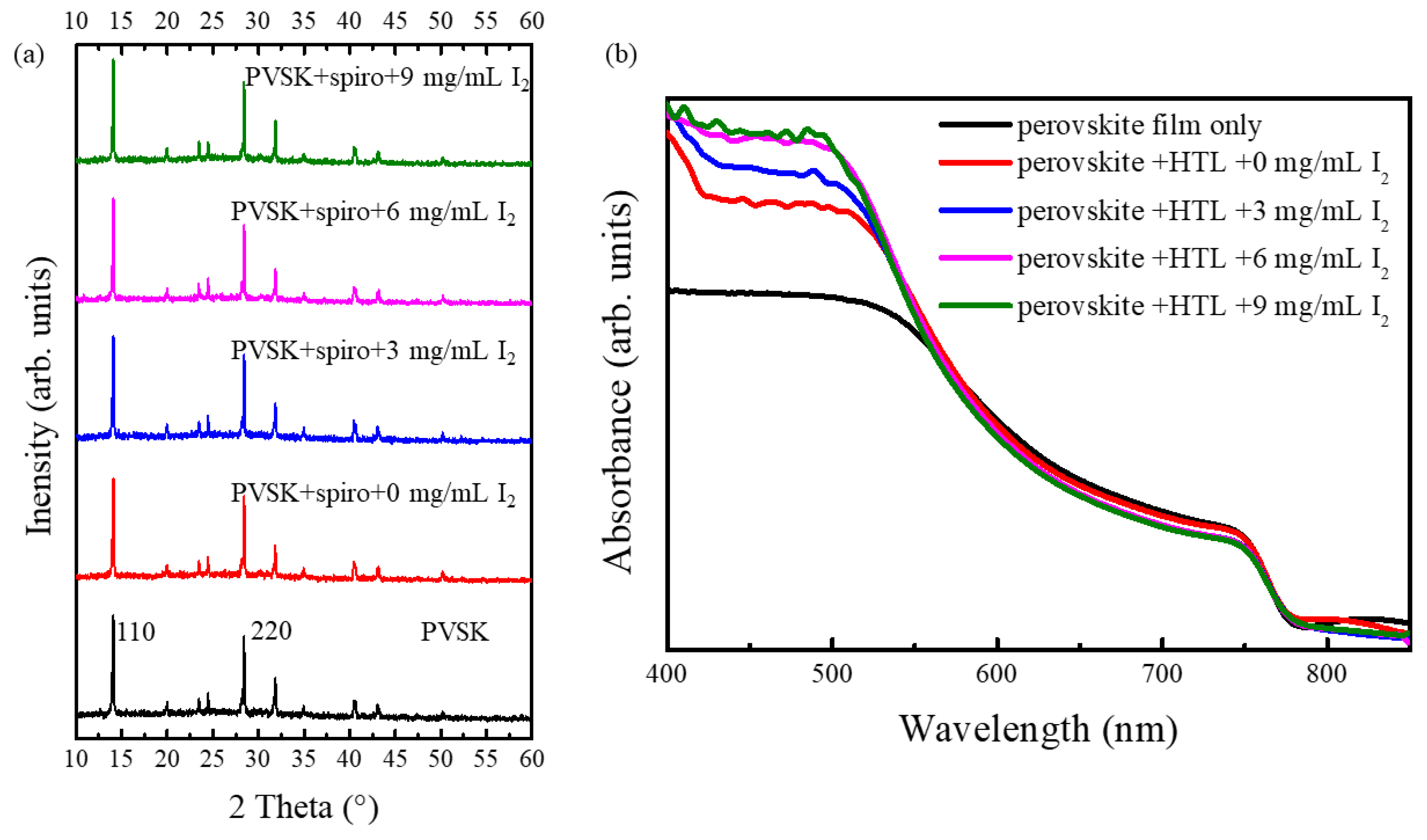
Figure 1. (a) XRD patterns of MAPbI3 thin film after coating with doped spiro-OMeTAD hole transport layer (HTL) layers; (b) UV–vis absorption of perovskite intrinsic film and with different doped spiro-OMeTAD HTL layers.
Crystals 08 00185 g001
Figure 2. (a) Absorption spectra of films of pristine and oxidized spiro-OMeTAD layers and the reduction of the polaronic band (≈500 nm) by reaction with I; (b) bandgap of perovskite films; the tangent line of the cutoff peak shows that the bandgap of all films is around 1.59 eV.
Crystals 08 00185 g002
Figure 3. Photovoltaic parameters of PSCs evaporated with gold electrode.
Crystals 08 00185 g003
Figure 4. (a) shows the transient photovoltage (TPV) results via angle shift and (b) exhibits the transient photocurrent (TPC) changed by switching angles.
Crystals 08 00185 g004
Figure 5. The XRD patterns of PSCs after one-week exposure in air.
Crystals 08 00185 g005