Article

Effect of Thermally Reduced Graphene Oxide on Mechanical Properties of Woven Carbon Fiber/Epoxy Composite

1
Surface Engineering and Tribology Division, Council of Scientific and Industrial Research-Central Mechanical Engineering Research Institute, Durgapur 713209, India
2
Academy of Scientific and Innovative Research (AcSIR), CSIR-CMERI, Campus, Durgapur 713209, India
*
Authors to whom correspondence should be addressed.
Crystals 2018, 8(3), 111; https://doi.org/10.3390/cryst8030111
Submission received: 12 January 2018 / Revised: 11 February 2018 / Accepted: 26 February 2018 / Published: 27 February 2018
(This article belongs to the Special Issue Graphene Mechanics)

Abstract

:
Thermally reduced graphene oxide (TRGO) was incorporated as a reinforcing filler in the epoxy resin to investigate the effect on the mechanical properties of carbon fiber (CF)/epoxy composites. At first, the epoxy matrix was modified by adding different wt % of TRGO from 0.05 to 0.4 wt % followed by the preparation of TRGO/CF/epoxy composites througha vacuum-assisted resin transfer molding process. The prepared TRGO was characterized by using Fourier transform infrared spectroscopy, Raman Spectroscopy and field emission scanning electron microscopy (FE-SEM) techniques. It was observed that the wrinkled structure of synthesized TRGO may be helpful to interlock with the epoxy resin and CF.The inter-laminar shear strength, in-plane fracture toughness and impact strength increased by ~67%, 62% and 93% at 0.2 wt % of TRGO loading in the CF/epoxy composites as compared to the CF reinforced epoxy. The mechanical properties of the hybrid composites decreased beyond the 0.2 wt % of TRGO incorporation in the epoxy resin. The fracture surfaces of the hybrid composites were studied by FE-SEM image analysis to investigate the synergistic effect of TRGO in the CF/epoxy composite. This study suggested that TRGO could be used asgood nanofiller to resist the matrix and fiber fracture.
Keywords:
fiber; shear; fracture; defect

1. Introduction

Carbon fiber (CF) reinforced epoxy composites are being widely used in many structural applications especially in aerospace and automotive industries due to their superior cost-effectiveness, high specific strength and light weight [1,2]. However, the on-road applications of the CF/epoxy laminates are limited owing to their inter-laminar failure, i.e., delamination and brittle nature of epoxy matrix [3,4]. The delamination deteriorates the mechanical strength and stiffness of the structures made off CF/epoxy composites. Most of the time, the laminas are buckled out from their plane due to the application of compressive and bending load [5]. The manufacturing imperfections, low-velocity impact and stress concentrations caused by sudden changes in laminate structure sometime are liable for the delamination of the composite laminates [6,7]. Thus, the resistance of the delamination phenomenon and impact damage is of great interest to composite researchers.
Many approaches have been applied to overcome the inter-laminar fracture problem and the most popular method is implanting a separate interlayer (either thermoplastic or thermosetting) between the adjacent laminas. The interlayer helps to form a mechanical linkage between crack interfaces and twisted crack paths and enhances the plane strain fracture toughness of the composite laminates [8]. Different kinds of nanofibrous membranes, films and nanofillers were used as interleaves in the composite laminates [9,10,11,12]. Dzenis et al. claimed that the electro-spun nanofibrous mats could be used for toughening the laminated composites [13]. The polybenzimidazole (PBI) electro-spun non-woven nanofibers were used as interleaves and showed the enhancement of mode I fracture toughness by ~15%. Consequently, different kinds of nanofibrous membranes such as polyacrylonitrile (PAN), polyamide, polycaprolactone (PCL), polyetherketonecardo (PEK-C) and polycarbonate (PC) were incorporated for improving the inter-laminar fracture toughness of the composite laminates [14,15,16,17,18]. Although, the nanofibrous membranes is helpful to enhance the fracture toughness of the laminates, but, the mismatch incompatibility between the fiber and matrix material leads to processing difficulties [19]. Extensive researches focused on the enhancement of inter-laminar fracture toughness (IFT) of the composites by modifying the epoxy matrix [20,21,22]. Different types of nanofillers, such as SiO2, Al2O3, TiO2, carbon nanotubes (CNT), graphene nanoplatelets (GNPs), etc. were used for the development of CF/epoxy composites [23,24,25,26,27]. Zeng et al. showed that nylon particles blended with the resin facilitated the enhancement of toughness of the CF/dicyanate composites [28]. Arai et al. investigated the IFT of CF/epoxy composites by introducing an interlayer of vapor grown carbon nanofiber (VGNF) and showed the mode I and mode II IFT improvement of ~50% and 200% compared to the pure CF/epoxy laminates [29]. Karapappas et al. reported the improvement of mode I and mode II fracture toughness by~63% and 70%, respectively by incorporating multiwall carbon nanotubes (MWCNT) in the CF/epoxy composites [30]. Though CNT and MWCNTs were considered as a superior matrix modifier, yet there are a few challenges like agglomeration, complicated surface modification and high production cost [31].The heterogeneous dispersion of resin and CNT restricts the flow of matrix during processing and creates defects i.e., voids, stress concentration, etc. in the laminate [32]. Some special techniques such as sonication, mechanical stirring, centrifugal mixing and the use of surfactant and chemical modification of nanofiller’s surfaces were opted for preparing homogeneous matrix dispersion [33]. Of late, graphene and its derivatives were used to enhance the matrix toughness and interfacial adhesive strength [34]. Extraordinary functionalities, mechanical strength, high surface area, effectiveness at deflecting cracks in bending/shear, chemical stability, conductivity, cost effectiveness, ultra high aspect ratio and abundance in nature of graphene makes it novel nanofiller for the production of fiber reinforced hybrid composite [35]. Du et al. investigated the effects of GO coating on the mechanical properties of short glass fiber (SGF) reinforced polyethersulphone composites and reported the improvement in tensile and flexural strength by 10.2% and 9.4%, respectively [36]. Kwon et al. coated GO/CNT on to the surface of CF by electrophoretic deposition (EPD) technique and showed an improvement of ~10% in short beam shear strength of the coated CF reinforced epoxy hybrid composite [37]. Lee et al. introduced EPD coating of partially reduced GO on the CF surface and enhanced by ~14% inter-laminar shear strength (ILSS) of the coated CF/epoxy composites [38]. Qin et al. studied the mechanical properties of GNPs coated CF/epoxy composites and showed ~19% improvement in ILSS than uncoated CF/epoxy composites [39]. Shen et al. observed the enhancement in cryogenic ILSS of the 0.3 wt % GO incorporated GF/epoxy composites than the base GF/epoxy composite [40]. Yavari et al. reported that the fatigue life could be improved up to 1200-fold by incorporating 0.2 wt % of graphene in the GF/epoxy composite [41]. Zhang et al. reported~12.7% improvement in ILSS of the unidirectional CF/epoxy composite by introducing GO sheet to the interfacial region of fiber and matrix material [42].
The majority of the previous studies reported the improvement of mechanical and electrical properties of different kinds of fibers (short, unidirectional long fiber and woven fabric of glass and carbon) reinforced composites prepared by different techniques such as electrophorectic deposition, hand lay-up, coating processes, etc. using graphene and its derivatives as nano-filler. In addition, they investigated the effect of GO on the mechanical properties of fiber reinforced epoxy composites. However, the use of GO as reinforcing filler in structural composite is not appropriate due to the presence of various types of oxygen functional groups in GO which may deteriorate the thermal stability of the resulting composites. Therefore, the use of chemically reduced GO or thermally reduced GO (TRGO) as reinforcing filler is always recommended to develop thermally stable structural composite materials. However, the use of chemically reduced GO for the fabrication of scaled-up structural components is not feasible due to the hazardous nature of chemical reducing agents, expensive chemicals and multi-step reduction reaction. Therefore, TRGO could be the best choice as reinforcing filler for epoxy-based composites. To the best of our knowledge, there is no report how the TRGO influenced the mechanical properties of the woven carbon fiber reinforced epoxy symmetric laminates. As reduced GO partially retains the intrinsic properties of graphene, thus it may exhibit significant effects on the mechanical properties of the composites. Thus, the use of TRGO could affect the mechanical properties of fiber reinforced epoxy composites. In this context, the present work intends to gain the basic understanding on the effect of TRGO on the mechanical properties of hybridized CF/epoxy laminate.The TRGO reinforced CF/epoxy laminate manufactured by vacuum assisted resin transfer molding (VARTM) process. The IFT, inter-laminar shear strength (ILSS) and Impact resistance were carried out to investigate the effect of TRGO on the delamination phenomena of the prepared hybrid composites. The interaction or interfacial adhesionbetween the fiber and matrix was examined by the field emission scanning electron microscopy (FE-SEM) images of the fractured specimens.

2. Experimental

2.1. Materials

Graphite flakes procured from India Mart, India was used for the preparation of TRGO. H2SO4 (98% v/v), HCl (35% v/v) and H2O2 (30% v/v) were obtained from Merck India. The CF used for this work is a plain weave carbon fabric with an areal density of 200 g/m2, thickness of 0.3 mm, ENDs (cm) 5 and PICKs (cm) 5. The filaments diameter is 6 micrometers. The CF fabric was purchased from Flips India Engineering (Mumbai, Indian) for reinforcement. Bisphenol-A epoxy resin (LAPOX*C-51) and modified cycloaliphatic amine hardener (Lapox AH-428) was bought from Atul Limited (Gujarat, India) to prepare the matrix system in this work. A heavy-duty silicon spray mold release agent and an adhesive spray were purchased from Aerol Formulation Pvt. Ltd. (New Delhi, India).

2.2. Fabrication of TRGO/CF/Epoxy Laminate

The TRGO was prepared by thermal reduction of GO, which was synthesized by modified Hummers method as reported in our earlier work [43]. In brief, ~1 g of freeze dried GO was taken in a alumina crucible and then placed inside a muffle furnace at ~600 °C for 3 min underargon atmosphere.The different amount of TRGO i.e., 50, 100, 200 and 400 mg TRGO was dispersed in 100 mL THF to prepare 0.05, 0.1, 0.2 and 0.4 wt % TGRO incorporated CF/epoxy composites as compared to the weight of the epoxy resin and curing agent. The required amount of TRGO was first dispersed in THF by sonication for 1 h in a water bath sonicator. The dispersion was then added into the epoxy resin to obtain the 0.05, 0.1, 0.2 and 0.4 wt % TRGO loaded epoxy composite. The TRGO/epoxy was further sonicated for 1 h to prepare homogeneous dispersion of TRGO and epoxy resin. The unwanted THF was removed under reduced pressure from the TRGO/epoxy mixture by evaporation at 85 °C for an hour. Later on the TRGO/epoxy suspension stirred for 6 h by using a magnetic stirrer with a speed of 250 rpm at ambient temperature. The required amount of curing agent was added into the TRGO/epoxy suspension and stirred at 600 rpm for about 3 min to obtain homogeneous mixing. Finally, modified TRGO/epoxy composite was obtained for the development of CF/TRGO/epoxy composite after degassing the TRGO/epoxy suspension inside a vacuum chamber. The woven CF fabrics were cut with a dimension of 160 × 200 mm and CF/TRGO/epoxy laminates were prepared by vacuum assisted resin transfer molding (VARTM) process. The VARTM process was carried out at room temperature. The lamina’s thickness was 0.3 mm. The symmetric laminates have material symmetry and geometric symmetry with respect to the mid-plane of the laminate plate. Geometric symmetry representsthe orientations of the laminas, above and below the mid-surface is identical. Material symmetry can result from either having all lamina the same material, or requiring different lamina to be symmetrically disposed about the mid-surface. The symmetric laminate is elected by subscript S on a square bracket i.e., []s. The 0/90 signifies a cross ply whose fibers are oriented in 0° and 90°. The stacking sequence of the lamina was [(0/90)9]s for the IFT, [(0/90)6]s for ILSS and [(0/90)7]s for impact test. The CF/TRGO/epoxy composite was cured at room temperature for 24 h and post cured at 80 °C for 2 h and 120 °C for 1 h. Finally, the required samples were cut from the laminates for testing.

2.3. Characterization

Fourier transform infrared (FT-IR) spectra of the synthesized TRGO were recorded with a PerkinElmer RXI FT-IR in the frequency range of 4000–400 cm−1. Field emission scanning electron microscopy (FE-SEM) was carried out with Ʃigma HD, Carl Zeiss, Germany to obtain the surface morphology of the TRGO and SENB fractured surfaces of the composites. The Raman spectra of the TRGO were obtained on a WITec alpha 300 (WITecWissenschaftlicheInstrumente und Technologie GmbH, Ulm, Germany) using a laser wavelength of 532 nm. The rheological properties of the TRGO/epoxy mixtures were determined by using a stress-controlled rotational rheometer MCR 501 (Anton Paar, Austria) set with a Peltier heating system and parallel plate-plate fixture of 25-mm. The gap size was determined in the range 0.7–1 mm depending on the TRGO content in epoxy resin. Steady shear measurements were conducted at shear rates in the range of 0.1–100 s−1 at 35 °C. Transmission electron microscope (TEM) of microtomed samples was carried out using a JEM 2100 instrument (JEOL Ltd., Tokyo, Japan) at 200 kV. The fiber volume fraction ( v f ) = ( w / f ) / ( W / c ) , matrix volume fraction ( v m ) = ( W w / m ) / ( W / c ) and void volume fractions ( v 0 ) = 1 − ( v f + v m ) of the prepared composites were determined using a matrix digestion test according to ASTM D 3171-99, where w , W , f , m and c are weight of fiber in the composite, weight of the initial composite specimen, density of fiber, matrix and composite respectively. The single edge notched bending (SENB) test was carried out according to the ASTM D5045to evaluate the fracture toughness of the prepared composites. The short beam shear test (SBS) of the composites was determined according to the ASTM D2344 to investigate the inter-laminar shear strength (ILSS) of the composites. Both the SBS and SENB tests were carried out using a universal testing machine (UTM) (Tinius Olsen, H50KS). The impact strength of the laminates was evaluated according to the ASTM D256 by using Izod impact tester. The specimen dimensions of ILSS, SENB and impact test are shown in Figure 1.

3. Results and Discussions

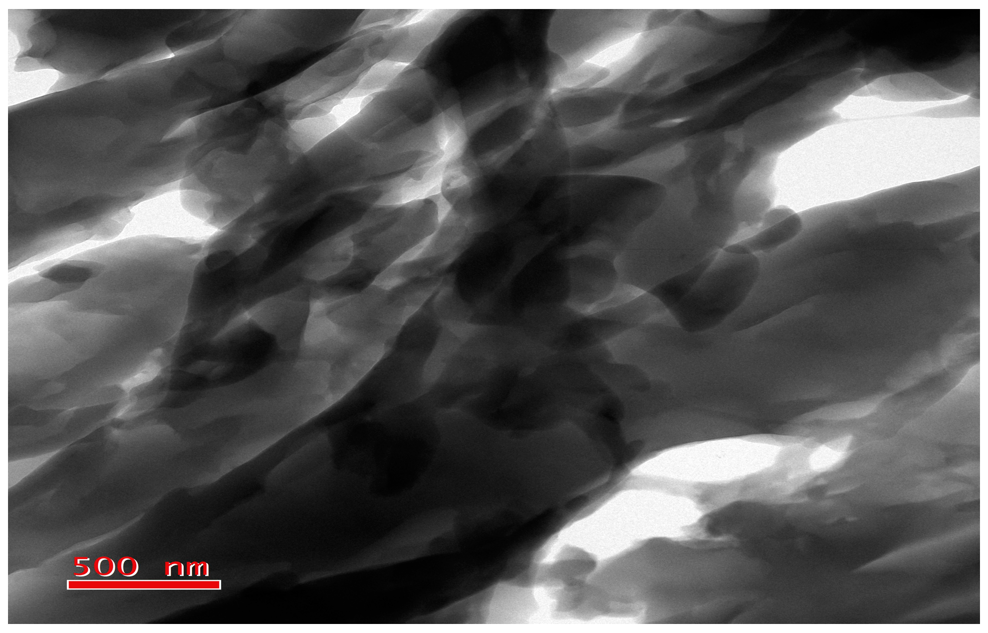
3.1. Structural and Morphological Study of TRGO

The presence of oxygen-containing functional groups in GO was investigated before and after thermal reduction of GO by FTIR, which is shown in Figure 2a. The oxygen-containing functional groups can be clearly identified prior to thermal reduction. GO shows a broad absorption peak centered at ~3432 cm−1, which can be attributed to the stretching vibration of –OH of water and GO [44]. The peak appeared at 1731 cm−1 can be attributed to the stretching vibrations of C=O for carboxyl and carbonyl groups present in GO. The two peaks appeared at 1369 cm−1 can be assigned to the bending vibration of –OH and the peak at 1052 cm−1can be attributed to C–O epoxide groups. The peak at 1731 cm−1 exhibits the sp2 character of graphite in thermally reduced GO. After the thermal reduction at 600 °C, the peaks related to –OH decreased significantly and the peak associated with C–O epoxide groups disappeared completely.
Raman spectroscopy is a well-known non-destructive technique to distinguish the electronic structure of graphite and graphene-derivative materials. Raman spectra of GO and TRGO are shown in Figure 2b. Generally, two peaks, one at 1575 cm−1 and another at 2700 cm−1 are used to characterize graphene and the related materials [45]. Chemically derived graphene and multi-crystalline graphite, exhibits an additional peak (D-band) at ~1355 cm−1. This D band is an indirect quantification of disorder arises due to the oxidation of graphite. Herein, GO exhibited two peaks; the G-band at 1593 cm−1 and the D band at 1348 cm−1. This is ascribed to the oxidation of graphite and the subsequent introduction of defects in the graphitic planes due to the addition of oxygen functionalities. In case of TRGO, the D-band appeared at 1351 cm−1and that of G-band at 1588 cm−1. The intensity ratio of the D-band to G-band is helpful to understand the degree of defects and restoration of π electron clouds in graphitic plane after reduction. In case of GO, the ID/IG ratio was found to be ~0.99 and that of TRGO the ratio was ~0.95. The decreased intensity ratio in case of TRGO indicated the restoration of π electronic conjugated structure after thermal reduction. Figure 2c,d show the FE-SEM images of GO and TRGO, respectively. The graphene sheets were folded with extensive wrinkles. It is likely that during thermal exfoliation, the exfoliated graphene sheets became unstable due high Van der Waals attraction, to achieve stability the layers tend to fold, hence the folded structure.

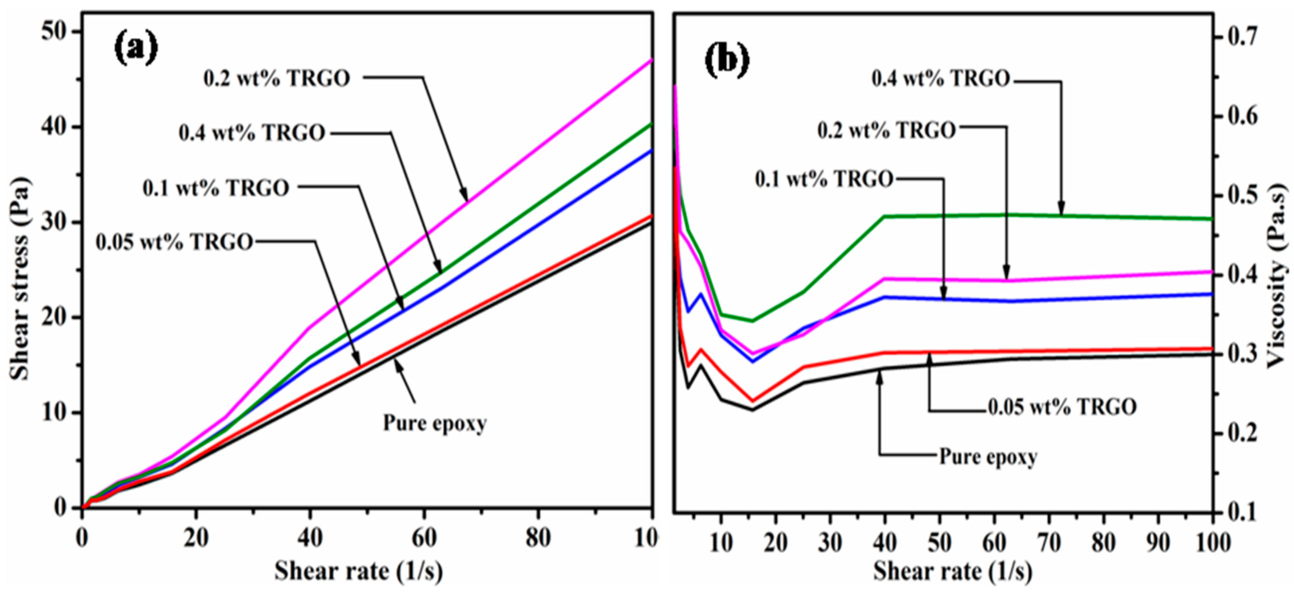
3.2. Effects of TRGO on the Viscoelastic Properties of Epoxy Resin

The steady shear rheological investigation was carried out with the aim to illustrate the behaviour of TRGO incorporated into the epoxy resin to find out the relation between absolute viscosities with TRGO loading. It is important to know the rheological behavior of the matrix material i.e., Newtonian or non-Newtonian for the optimization of TRGO content during the preparation of composite materials. Figure 3 shows the steady shear rheological analysis of the epoxy resin containing different concentration of TRGO in terms of shear stress and viscosity as a function of shear rate at 35 °C. Figure 3a shows the variation of shear stress with the variation of shear rate of the TRGO/epoxy composite. It was found that the induced shear stress increased upto 0.2 wt % of TRGO loading and beyond this concentration, the shear stress value of the TRGO/epoxy composite decreased. The viscosity of the TRGO/epoxy composite as a function of shear rate remained constant within the range of 25–100 s−1as shown in Figure 3b. But, the viscosity of the composite increased constantly with the increment of TRGO content. The curves of both the Figure 3a, brepresents that the TRGO/epoxy mixture behaved like a Newtonian fluid.
TEM image analysis of TRGO/epoxy composites showed the direct observation of dispersed TRGO sheets. It is the most familiar microscopic technique for determining the state of dispersion of reinforcing filler in the matrix material. Thicker sheets usually show the sufficient contrast against the epoxy resin, whereas the observation of a single layer graphene in the polymer matrix is quite difficult. Figure 4 shows the TEM image of 0.2 wt % of TRGO/epoxy composites. It showed that the TRGO was homogeneously dispersed in the epoxy resin.

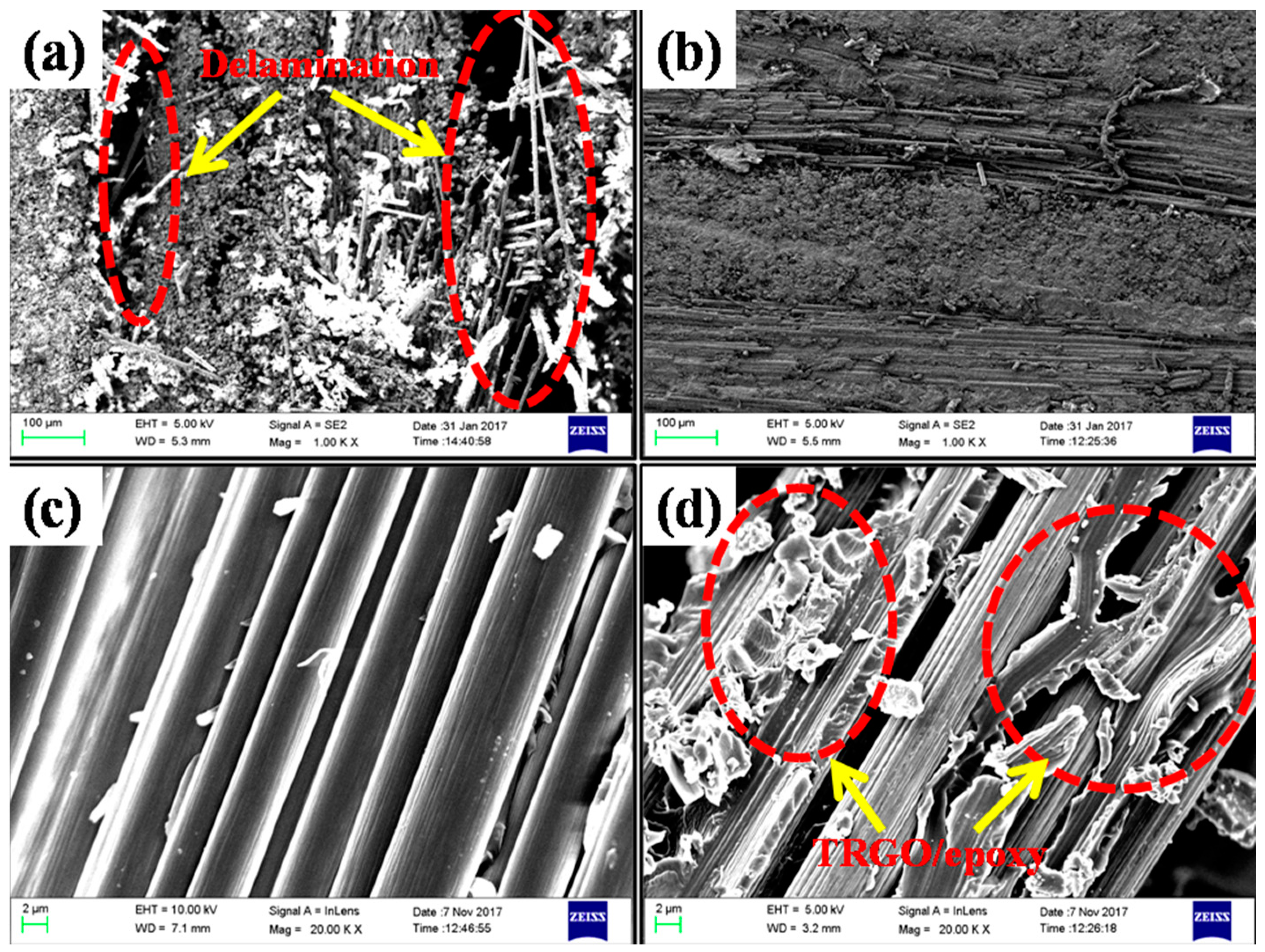
3.3. Fracture Surface Morphology Analysis

The morphology of the fracture surfaces of pure CF/epoxy and 0.2 wt % loaded TRGO/CF/epoxy composite was studied by ILSS and SENB tests to investigate the fracture mechanism of the prepared composites. The fiber-polymer composites enhanced the fracture toughness by consuming some amount of the elastic energy during failure like matrix fracture, fiber pullout, fiber-matrix de-bonding, etc. [46]. So, the overall mechanical properties of the composites depend on each component represent in the composite material. The fiber breakage and fiber pull out failure mechanism absorbs more energy compared to the matrix failure. The fiber failure in the composites occurred because of the low adhesion and interfacial strength between fiber and matrix. The fracture surface morphology of the CF/epoxy and TRGO/CF/epoxy composites after ILSS and SENB tests are shown in Figure 5a–d. It was observed that the SENB fracture surface of CF/epoxy composite was smoother as compared to the TRGO incorporated CF/epoxy composites and it was shown in Figure 5c,d. The incorporation of TRGO in the CF/epoxy composites made the fiber surfaces rougher. This was due to the toughening effect of TRGO in the epoxy resin. The incorporation of TRGO obstructs the propagation of generated cracks along the axis of fibers in the composites and enhanced the toughness of the composites. It also reduced the stress concentration in the composites and improved the inter-laminar adhesion between CF and epoxy resin. Davis et al. observed similar phenomenon by incorporating fluorine functionalized carbon nanotubes (f-CNTs) in the CF/epoxy composites [47]. They suggested that the incorporation of CNTs in the matrix material improved the fracture toughness of the composites by consuming more energy compared to neat CF/epoxy specimens. In this concern, TRGO facilitated the bridging between fiber and matrix material and thus improved the toughness of the composites. The branched cracking of matrix absorbed more energy under loading condition and showed improved fracture toughness of the prepared composites. The fracture sample of pure CF/epoxy composites after ILSS test showed a wide gap between the two laminas as compared to the TRGO/CF/epoxy hybrid composites as shown in Figure 5a,b. It revealed that the delamination of the CF/epoxy composites could be improved by incorporating TRGO in the composites. So, after the investigation of the fracture morphology of the prepared composites, it is confirmed that TRGO not only enhance the fracture toughness of the composites but also the ILSS and impact strength.

3.4. Volume Fraction of the Constituents

The volume fraction of fiber, matrix and void was summarized in Table 1. It was noticed that v f , v m and v 0 varied by 54–56, 43–44 and 1–2%, respectively. The value of v 0 in the composites increased because of increment of the viscosity of the epoxy resin. Viscosity of the epoxy matrix was increased as compared to the neat epoxy resin as the incorporation of TRGO was increased in the epoxy resin. The highly viscous TRGO incorporated epoxy matrix restricted the flow rate of the matrix material during the preparation of the hybrid composites. The flow rate of the TRGO incorporated epoxy resin decreased in transverse direction during infusion of laminated panel. As a result, entrapped air was more in the hybrid composite and reduced the mechanical strength of the composites.

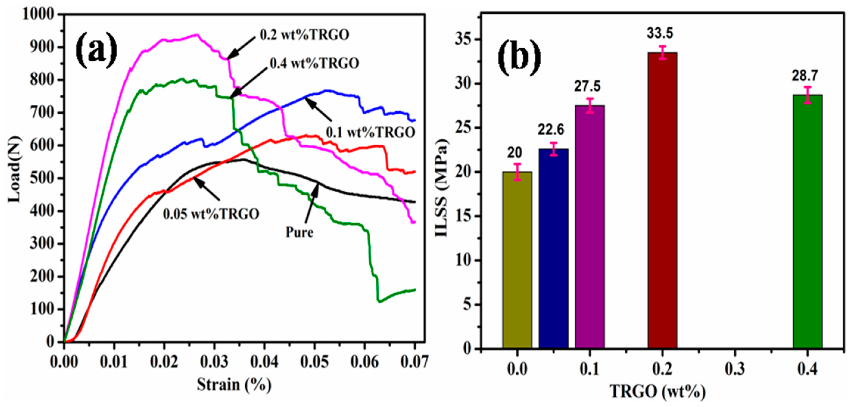
3.5. Interlaminar Shear Strength (ILSS)

The delamination failure occurred between the CF laminas as the generated shear stress under transverse loading on the CF/epoxy laminate exceeds the ILSS of the composite. Hence, ILSS is a major criterion to investigate the mechanical properties of the CF/epoxy composites. The ILSS of the laminate is generally evaluated by short beam shear (SBS) test method following the classical Euler-Bernoulli beam theory. In this work, ILSS of the CF/epoxy composites was determined following the equation I L S S = 0.75 P b w t , where Pb, w and t are the breaking load, width and thickness of the test specimens. The applied load increased gradually with the deformation of the samples, until a peak load is reached. It is anticipated that the composite failed during laminar shear when the applied load dropped by ~40% after attaining the peak load. The peak load could be considered as the determining factor of the ILSS for the prepared composites. Figure 6a shows the typical load-displacement curve of each TRGO hybridized CF/epoxy composite. Though, four samples of each hybridized composites were tested, but for the sake of transparency, only single specimen’s load-deformation curve has been presented. The load carrying capacity of the TRGO modified CF/epoxy was more than pure CF/epoxy composite and it also increased with the increment of TRGO content in the prepared composites. Similarly, the ILSS of the TRGO/CF/epoxy composite increased as the ILSS is directly proportional to the load carrying capacity of the composites. But the ILSS of the composites decreased beyond 0.2 wt % loading of TRGO in the CF/epoxy composites. This observation affirmed that the epoxy resin could be modified by the incorporation of TRGO up to a certain limit. The excess incorporation of TRGO in epoxy matrix may cause incompatible dispersion or agglomeration. The matrix viscosity also increased, and the flow rate of the epoxy resin decreased during the infusion process. The lack of infusion of the laminas may create micro voids in the laminate and deteriorates the ILSS of the prepared composite. The bar chart of ILSS vs. wt % of TRGO is shown in Figure 6b. The measured ILSS of each TRGO/CF/epoxy composite varies in between 2–3 MPa. The maximum improvement of ILSS of the prepared CF/epoxy composites was recorded at 0.2 wt % of TRGO loading. The ILSS of 0.2 wt % TRGO incorporated CF/epoxy improved ~67% as compared to the pure CF/epoxy composite. The enhancement of ILSS of the prepared composites indicated good adhesion between CF and TRGO modified epoxy matrix. The overall ILSS of the prepared composites are given in Table 2. The ILSS represents the resistance under transverse load of the composites but how the composites resist the crack propagation under transverse load in presence of a crack, i.e., fracture toughness is described in the next paragraph.

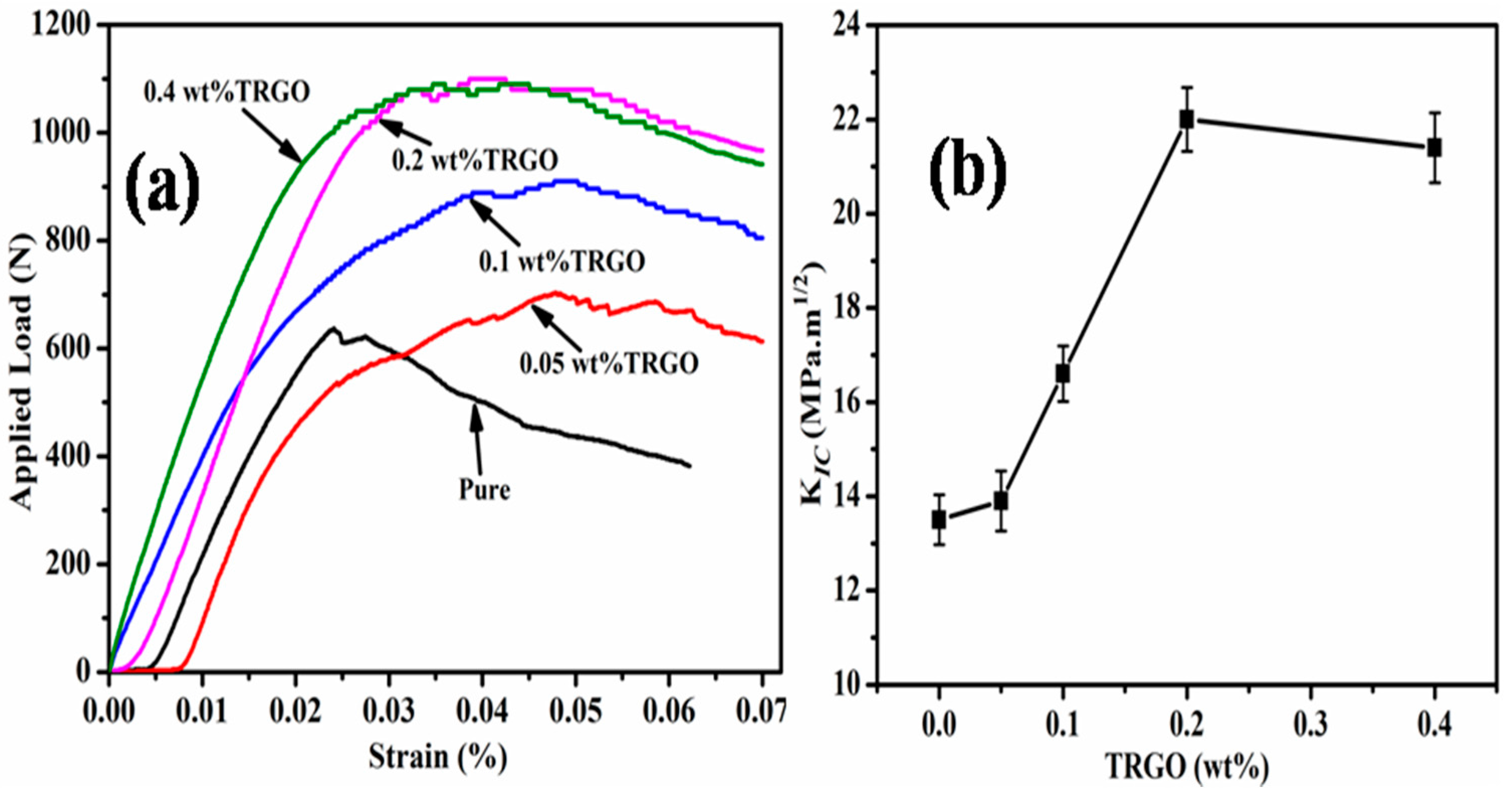
3.6. Plane-Strain Fracture Toughness

The relevant improvement in fracture toughness of the TRGO/CF/epoxy composites is described in this section. The fracture toughness is generally expressed in terms of critical-stress-intensity factor (KIC) and the critical strain energy release rate (GIC) at the initiation of fracture in the composites. The GIC is defined as the energy required for the crack propagation in the material [48]. According to the ASTM D5045, the value of KIC is expressed by the Equation (1) and to satisfy the Equation (1), it must go after the Equation (2) [49].
K Q = ( P Q B W 1 / 2 ) f ( x )
where, (0 < x < 1), f ( x ) = 6 x 1 / 2 [ 1.99 x ( 1 x ) ( 2.15 3.93 x + 2.7 x 2 ) ] ( 1 + 2 x ) ( 1 x ) 3 / 2 .
P Q = applied load, B = specimen thickness, w = specimen width, a = crack length and x = a/w
B ,   a ,   ( w a )   >   2.5 ( K Q σ y ) 2
where, K Q = the conditional or trial KIC value and σ y = the yield stress of the material.
Figure 7a shows load vs. displacement curve of the pure CF/epoxy composite and TRGO incorporated CF/epoxy composites. The load carrying capacity of the TRGO/CF/epoxy composites increased compared to the pure CF/epoxy composite. The deformation of the CF/epoxy composites increased linearly up to a certain limit with the increment of the applied load and then deformed non-linearly. The maximum load (Pmax) was determined for the calculation of KIC according to the equation, Pmax/ P Q < 1.1. The Pmax of the TRGO/CF/epoxy composites increased with the increment of the TRGO loading in the composites. Beyond the 0.02 wt % TRGO loading in the CF/epoxy composites, the Pmax of the TRGO/CF/epoxy composites decreased as shown in Figure 7a. The maximum load carrying capacity of the composites is about 1034 N at 0.2 wt % TRGO content. The minimum load carried by pure CF/epoxy composite was about 635 N. The bar chart of KIC vs. wt % of TRGO in the prepared TRGO/CF/epoxy composites is shown in Figure 7b. The GIC was measured directly by integrating the load versus displacement curve up to the same load point as used for calculating KIC. GIC is the minimum energy required for propagating the existing fracture of the prepared materials. The GIC of the TRGO/CF/epoxy composites increased due to the enhancement of the interfacial interaction between TRGO and epoxy matrix. But the GIC of the TRGO/CF/epoxy composites at 0.4 wt % of TRGO loading decreased compared to 0.2 wt % TRGO content. It may be attributed to the presence of micro voids in the TRGO/CF/epoxy composites with 0.4 wt % of TRGO loading. Therefore, the excess loading of TRGO in the composites not only increased the viscosity but also resulted poor wetting of TRGO with the epoxy matrix. This agglomeration of TRGO and high viscosity of the epoxy resin created micro voids in the composites which deteriorated the load bearing capacity of the prepared composites and corresponding value of GIC. The calculated value of all parameters related to the in-plane fracture toughness of the prepared CF/epoxy composites has been summarized in the Table 3.
Besides the ILSS and SENB test, the impact property analysis of CF/epoxy composites is very important for the failure analysis of the CF/epoxy composite as the impact damage induced in the laminated composite structure used for primary load bearing criterion in different structural applications. There may be some unexpected damage during in-service conditions such as mechanical and thermal shock, acoustic shock, electromagnetic irradiation etc. This unexpected damage may also happen due to impacts during operations of flight like impacting of runway debris and bird-strikes during on composite airframes. The effect of impact load on the prepared composites is described in the next section.

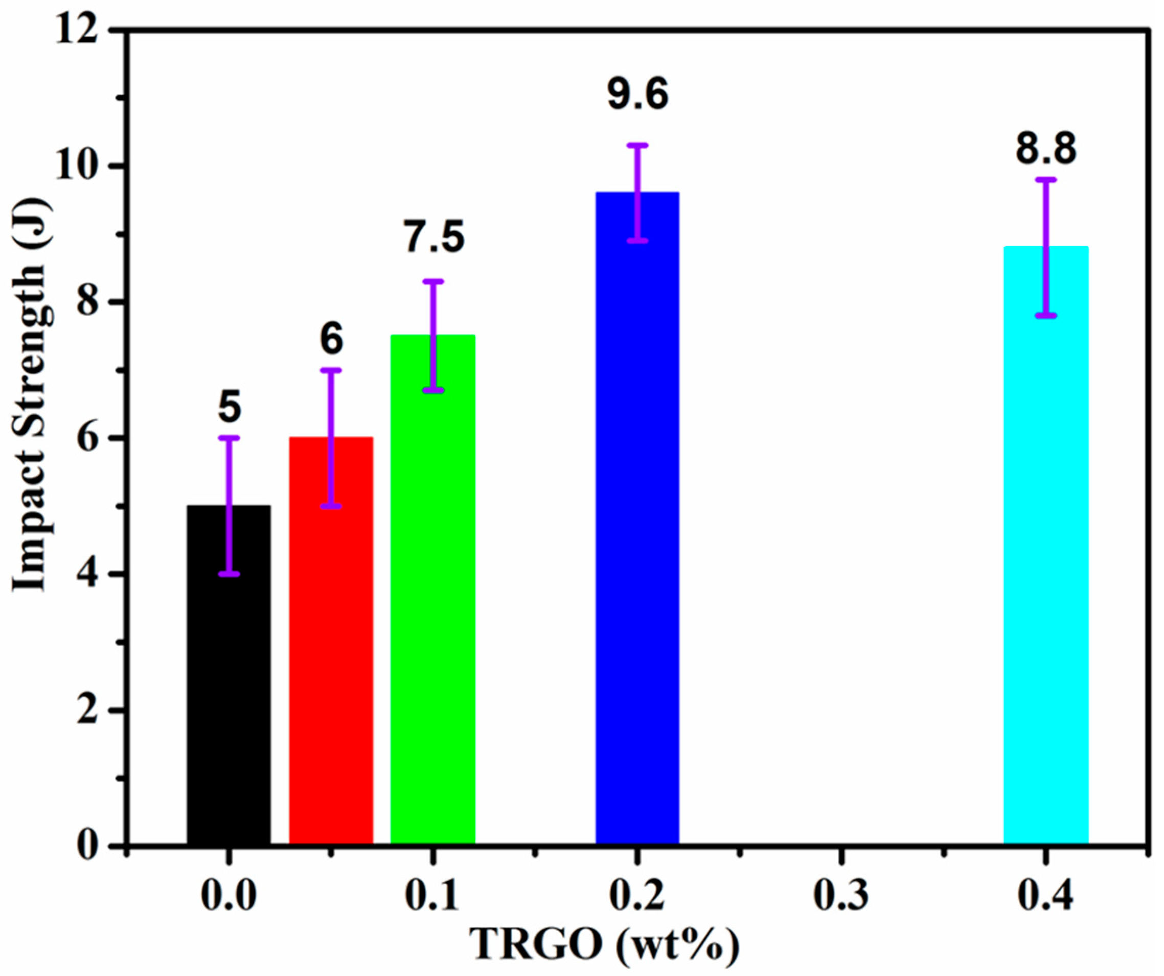
3.7. ImpactProperties Analysis

Most of the damage under impact load in the laminated composites was found as internal defects. The internal defects are generally originated due to the matrix cracking and fiber breakage at micro level which are not easily detected on the surface of the specimen. But at macro level, it is observed as interlayer failure or delamination. Some energy is required for the failure of the CF/epoxy composites during matrix cracking and fiber breakage under impact load [50]. The required energy is known as impact fracture toughness of the composites. Therefore, failure type is dependent on impact toughness of the laminates. The energy absorbed by the laminate is the sum of the energy absorbed by each constituent material. So, the impact toughness of the CF/epoxy laminate can be enhanced by improving the individual impact toughness of the constituent material. Here, an attempt was taken to improve the impact toughness of the epoxy resin by incorporating different wt % of TRGO for the overall improvement of the impact toughness of the CF/epoxy composites as the epoxy matrix fails under impact load. The Izod impact toughness of pure CF/epoxy and TRGO/CF/epoxy composites at different wt % of the TRGO loading is shown in Figure 8. It was observed that the incorporation of TRGO improved the impact strength of the CF/epoxy composites.

4. Conclusions

The improvement of ILSS, in-plane fracture toughness and impact toughness of the CF/epoxy composites was investigated by using TRGO as filler material. The TRGO was prepared by simple reduction of GO at high temperature (600 °C). The partial reduction was carried out to get the graphene like properties of GO. The TRGO/CF/epoxy composite laminates were manufactured by the VARTM process after modifying the epoxy resin by TRGO. The partial reduction of GO made its surface more wrinkled compared to GO surface. The wrinkled surface texture of TRGO promoted mechanical interlocking with epoxy resin, thereby enhancing the load transfer capability of the CF/epoxy composite. The good adhesion between CF and TRGO modified epoxy resin also increased the ILSS (50%), fracture toughness (40%) and impact toughness (93%) up to a certain limit of TRGO content (0.2 wt%) present in the prepared composites. The excess incorporation of TRGO also agglomerates in the epoxy resin and makes micro voids in the CF/epoxy composites. The micro voids reduced the mechanical properties of the TRGO/CF/epoxy composites. Considering the overall performance of TRGO in the CF/epoxy, it could be explored in the areas of automotive, aerospace and other allied industries.

Acknowledgments

Authors are thankful to the Director of CSIR-CMERI. Authors are also thankful to Department of Science and Technology, New Delhi, India for the financial supports (GAP215312).

Author Contributions

Pranab Samanta and Tapas Kuila designed and coordinated the research work. Nitai C. Adak and Suman Chhetri performed all the experiments. Naresh C. Murmu analyzed the mechanical testing’s of the developed materials and all the authors assisted the assembly and editing of the manuscript.

Conflicts of Interest

The authors declare no conflict of interest.

References

  1. Kim, J.K.; Mai, Y.W. High strength, high fracture toughness fibre composites with interface control-a review. Compos. Sci. Technol. 1991, 41, 333–378. [Google Scholar] [CrossRef]
  2. Adak, N.C.; Chhetri, S.; Kim, N.H.; Murmu, N.C.; Samanta, P.; Kuila, T. Static and Dynamic Mechanical Properties of Graphene Oxide-Incorporated Woven Carbon Fiber/Epoxy Composite. J. Mater. Eng. Perform. 2018. [Google Scholar] [CrossRef]
  3. Jin, J.C.; Sun, C.T. Prediction of delamination in composite laminates subjected to low velocity impact. J. Compos. Mater. 1993, 27, 684–701. [Google Scholar]
  4. Choi, N.S.; Kinloch, A.J.; Williams, J.G. Delamination fracture of multidirectional carbon-fiber/epoxy composites under Mode I. Mode II and mixed-Mode I/II loading. J. Compos. Mater. 1999, 33, 73–99. [Google Scholar] [CrossRef]
  5. James, R.; Song, R.K.; Chunchu, P.; Ambur, D.R. Postbukling and growth of delamination in composite plates subjected to axial compression. In Proceedings of the 43rd AIAA/ASME/ASCE/AHS/ASC Structures, Structural Dynamics, and Materials Conference, Denver, CO, USA, 22–25 April 2002; p. 1746. [Google Scholar]
  6. Greenhalgh, E.S.; Rogers, C.; Robinson, P. Fractographic observations on delamination growth and the subsequent migration through the laminate. Compos. Sci. Technol. 2009, 69, 2345–2351. [Google Scholar] [CrossRef]
  7. Greenhalgh, E.S. Woodhead Publishing Series in Composites Science and Engineering; CRC Press: Boca Raton, FL, USA, 2009; pp. 164–165. [Google Scholar]
  8. Chen, C.Z.; Li, Y.; Yu, T. Interlaminar toughening in flax fiber-reinforced composites interleaved with carbon nanotube buckypaper. J. Reinf. Plast. Compos. 2014, 33, 1859–1868. [Google Scholar] [CrossRef]
  9. Palazzetti, R.; Zucchelli, A.; Gualandi, C.; Focarete, M.L.; Donati, L.; Minak, G.; Ramakrishna, S. Influence of electrospun Nylon 6,6 nanofibrous mats on the interlaminar properties of Gr–epoxy composite laminates. Compos. Struct. 2012, 94, 571–579. [Google Scholar] [CrossRef]
  10. Jiang, W.; Tjong, S.C.; Chu, P.K.; Li, R.K.Y.; Kim, J.K.; Mai, Y.-W. Interlaminar fracture properties of carbon fibre/epoxy matrix composites interleaved with polyethylene terephthalate (PET) films. Polym. Polym. Compos. 2001, 9, 141–145. [Google Scholar]
  11. Yuna, N.G.; Wona, Y.G.; Kimb, S.C. Toughening of carbon fiber/epoxy composite by inserting polysulfone film to form morphology spectrum. Polymer 2004, 45, 6953–6958. [Google Scholar] [CrossRef]
  12. White, K.L.; Sue, H.J. Structural composites hybridized with epoxy compatible polymer/MWCNT nanofibrous interlayers. Polymer 2012, 53, 37–42. [Google Scholar] [CrossRef]
  13. Dzenis, Y.; Reneker, D. Delamination Resistant Composite Prepared by Small Diameter Fiber Reinforcement at Ply Interfaces. U.S. Patent No. 6,265,333, 24 July 2001. [Google Scholar]
  14. Sihn, S.; Kim, R.Y.; Huh, W.; Lee, K.H.; Roy, A.K. Improvement of damage resistance in laminated composites with electrospunnano-interlayers. Compos. Sci. Technol. 2008, 68, 673–683. [Google Scholar] [CrossRef]
  15. Lingaiah, S.; Shivakumar, K.N.; Sadler, R.; Sharpe, M. Electrospinning of nylon-66 polymer Nanofabrics. In Proceedings of the 49th AIAA/ASME/ASCE/AHS/ASC Structures, Structural Dynamics and Materials Conference, Honolulu, HI, USA, 7–10 April 2008; p. 1. [Google Scholar]
  16. Heijden, S.V.; Daelemans, L.D.; Schoenmaker, B.D. Interlaminar toughening of resin transfer moulded glass fibre epoxy laminates by polycaprolactoneelectrospunnanofibers. Compos. Sci. Technol. 2014, 104, 66–73. [Google Scholar] [CrossRef]
  17. Zhang, J.; Lin, T.; Wang, X. Electrospunnanofibre toughened carbon/epoxy composites: Effects of polyetherketonecardo (PEK-C) nanofibre diameter and interlayer thickness. Compos. Sci. Technol. 2010, 70, 1660–1666. [Google Scholar] [CrossRef]
  18. Magniez, K.; Chaffraix, T.; Fox, B. Toughening of a Carbon-Fibre Composite Using Electrospun Poly(Hydroxyether of Bisphenol A) Nanofibrous Membranes Through Inverse Phase Separation and Inter-Domain Etherification. Materials 2011, 4, 1967–1984. [Google Scholar] [CrossRef] [PubMed]
  19. Zheng, N.; Huang, Y.; Liu, H.Y.; Gao, J.; Mai, Y.W. Improvement of interlaminar fracture toughness in carbon fiber/epoxy composites with carbon nanotubes/polysulfone interleaves. Compos. Sci. Technol. 2017, 140, 8–15. [Google Scholar] [CrossRef]
  20. Todo, M.; Jar, P.Y.B. Study of mode I interlaminar crack growth of fibre reinforced composites using DCB specimens. Compos. Sci. Technol. 1998, 58, 105–118. [Google Scholar] [CrossRef]
  21. Singh, S.; Partridge, I.K. Delamination failure in unidirectional carbon fibre/epoxy under mixed mode loading. Polym. Polym. Compos. 1995, 3, 35–39. [Google Scholar]
  22. Hwang, S.F.; Shen, B.C. Opening-mode interlaminar fracture toughness of interplyhybride composite materials. Compos. Sci. Technol. 1999, 59, 1861–1869. [Google Scholar] [CrossRef]
  23. Rocha, R.M.; Cairo, C.A.A.; Graca, M.L.A. Formation of carbon fiber-reinforced ceramic matrix composites with polysiloxane/silicon derived matrix. Mater. Sci. Eng. 2006, 437, 268–273. [Google Scholar] [CrossRef]
  24. Kachold, F.; Singer, R. Mechanical Properties of Carbon Fiber-Reinforced Aluminum Manufactured by High-Pressure Die Casting. J. Mater. Eng. Perform. 2016, 25, 3128–3133. [Google Scholar] [CrossRef]
  25. Cai, F.; Gao, F.; Pant, S.; Huang, X.; Yang, Q. Solid Particle Erosion Behaviors of Carbon-Fiber Epoxy Composite and Pure Titanium. J. Mater. Eng. Perform. 2016, 25, 290–296. [Google Scholar] [CrossRef]
  26. Spitalsky, Z.; Tasis, D.; Papagelis, K.; Galiotis, C. Carbon nanotube-polymer composites: Chemistry, processing, mechanical and electrical properties. Prog. Polym. Sci. 2010, 35, 357–401. [Google Scholar] [CrossRef]
  27. Liu, N.; Luo, F.; Wu, H.; Liu, Y.; Zhang, C.; Chen, J. Onestep ionic-liquid-assisted electrochemical synthesis of ionicliquid-functionalized graphene sheets directly from graphite. Adv. Funct. Mater. 2008, 18, 1518–1525. [Google Scholar] [CrossRef]
  28. Zeng, S.; Hoisington, M.; Seferis, J.C. Particulate interlayer toughening of dicyanate matrix composites. Polym. Compos. 1993, 14, 458–466. [Google Scholar] [CrossRef]
  29. Arai, M.; Noro, Y.; Sugimoto, K.I.; Endo, M. Mode I and mode II interlaminar fracture toughness of CFRP laminates toughened by carbon nanofiber interlayer. Compos. Sci. Technol. 2008, 68, 516–525. [Google Scholar] [CrossRef]
  30. Karapappas, P.; Vavouliotis, A.; Tsotra, P.; Kostopoulos, V.; Paipetis, A. Enhanced fracture properties of carbon reinforced composites by the addition of multi-wall carbon nanotubes. J. Compos. Mater. 2009, 43, 977–985. [Google Scholar] [CrossRef]
  31. Seyhan, A.T.; Tanoglu, M.; Schulte, K. Mode I and mode II fracture toughness of E-glass non-crimp fabric/carbon nanotube (CNT) modified polymer based composites. Eng. Fract. Mech. 2008, 75, 5151–5162. [Google Scholar] [CrossRef]
  32. Tang, L.C.; Zhang, H.; Han, J.H.; Wu, X.P.; Zhang, Z. Fracture mechanisms of epoxy filled with ozone functionalized multi-wall carbon nanotubes. Compos. Sci. Technol. 2011, 72, 7–13. [Google Scholar] [CrossRef]
  33. Esposito, L.H.; Ramos, J.A.; Kortaberria, G. Dispersion of carbon nanotubes in nanostructured epoxy systems for coating application. Prog. Org. Coat. 2014, 77, 1452–1458. [Google Scholar] [CrossRef]
  34. Rafiee, M.A.; Rafiee, J.; Wang, Z.; Song, H.H.; Yu, Z.Z.; Koratkar, N. Enhanced Mechanical Properties of Nanocomposites at Low Graphene Content. ACS Nano 2009, 3, 3884–3890. [Google Scholar] [CrossRef] [PubMed]
  35. Stankovich, S.; Dikin, D.A.; Dommett, G.H.B.; Kohlhaas, K.M.; Zimney, E.J.; Stach, E.A.; Piner, R.D.; Nguyen, S.T.; Ruoff, R.S. Graphene-based composite materials. Nature 2006, 442, 282–286. [Google Scholar] [CrossRef] [PubMed]
  36. Du, S.S.; Li, F.; Xiao, H.M.; Li, Y.Q.; Hu, N.; Fu, S.Y. Tensile and flexural properties of graphene oxide coated-short glass fiber reinforced polyethersulfone composites. Compos. Part B 2016, 99, 407–415. [Google Scholar] [CrossRef]
  37. Kwon, Y.J.; Kim, Y.; Jeon, H.; Cho, S.; Lee, W.; Lee, J.U. Graphene/carbon nanotube hybrid as a multi-functional interfacial reinforcement for carbon fiber-reinforced composites. Compos. Part B 2017, 122, 23–30. [Google Scholar] [CrossRef]
  38. Lee, W.; Lee, J.U.; Cha, H.J.; Byun, J.H. Partially reduced graphene oxide as a multi-functional sizing agent for carbon fiber composites by electrophoretic deposition. RSC Adv. 2013, 3, 25609–25613. [Google Scholar] [CrossRef]
  39. Qin, W.; Vautard, F.; Drzal, L.T.; Yu, J. Mechanical and Electrical Properties of Carbon Fiber Composites with Incorporation of Graphene Nanoplatelets at the Fiber-Matrix Interphase. Compos. Part B 2015, 69, 335–341. [Google Scholar] [CrossRef]
  40. Shen, X.J.; Meng, L.X.; Yan, Z.Y.; Sun, C.J.; Ji, Y.H.; Xiao, H.M.; Fu, S.Y. Improved cryogenic interlaminar shear strength of glass fabric/epoxy composites by graphene oxide. Compos. Part B 2015, 73, 126–131. [Google Scholar] [CrossRef]
  41. Yavari, F.; Rafiee, M.A.; Rafiee, J.; Yu, Z.Z.; Koratkar, N. Dramatic Increase in Fatigue Life in Hierarchical Graphene Composites. ACS Appl. Mater. Interfaces 2010, 10, 2738–2743. [Google Scholar] [CrossRef] [PubMed]
  42. Zhang, X.; Fan, X.; Yan, C.; Li, H.; Zhu, Y.; Li, X.; Yu, L. Interfacial Microstructure and Properties of Carbon Fiber Composites Modified with Graphene Oxide. ACS Appl. Mater. Interfaces 2012, 4, 1543–1552. [Google Scholar] [CrossRef] [PubMed]
  43. Kuila, T.; Bose, S.; Khanra, P.; Mishra, A.K.; Kim, N.H.; Lee, J.H. A green approach for the reduction of graphene oxide by wild carrot root. Carbon 2012, 50, 914–921. [Google Scholar] [CrossRef]
  44. Liu, X.; Qi, X.; Zhang, Z.; Ren, L.; Hao, G.; Liu, Y.; Wang, Y.; Huang, K.; Wei, X.; Li, J.; et al. Electrochemically reduced graphene oxide with porous structure as a binder-free electrode for high-rate supercapacitors. RSC Adv. 2014, 4, 13673–13679. [Google Scholar] [CrossRef]
  45. Mou, Z.; Chen, X.; Du, Y.; Wang, X.; Yang, P.; Wang, S. Forming mechanism of nitrogen doped graphene prepared by thermal solid-state reaction of graphite oxide and urea. Appl. Surf. Sci. 2011, 258, 1704–1710. [Google Scholar] [CrossRef]
  46. Park, B.Y.; Kim, W.S.C.; Jung, B. Interlaminar Fracture Toughness of Carbon Fiber/Epoxy Composites using Short Kevlar Fiber and/or Nylon-6 Powder Reinforcement. Polym. Adv. Technol. 1997, 8, 371–377. [Google Scholar] [CrossRef]
  47. Davis, D.C.; Whelan, B.D. An experimental study of interlaminar shear fracture toughness of a nanotube reinforced composite. Compos. Part B Eng. 2011, 42, 105–116. [Google Scholar] [CrossRef]
  48. Chhetri, S.; Adak, N.C.; Samanta, P.; Mallisetty, P.K.; Murmu, N.C.; Kuila, T. Interface engineering for the improvement of mechanical and thermal properties of covalent functionalized graphene/epoxy composites. J. Appl. Polym. Sci. 2017, 46124, 1–10. [Google Scholar] [CrossRef]
  49. Chhetri, S.; Adak, N.C.; Samanta, P.; Murmu, N.C.; Kuila, T. Functionalized reduced graphene oxide/epoxy composites with enhanced mechanical properties and thermal stability. Polym. Test. 2017, 63, 1–11. [Google Scholar] [CrossRef]
  50. Zhang, Z.Y.; Richardson, M.O.W. Low velocity impact induced damage evaluation and its effect on the residual flexural properties of pultruded GRP composites. Compos. Struct. 2007, 81, 195–201. [Google Scholar] [CrossRef]
Figure 1. Geometry and dimension of (a) In-plane fracture toughness (b) Inter-laminar shear strength and (c) Izod impact test specimens.
Crystals 08 00111 g001
Figure 2. (a) FTIR and (b) Raman Spectrum and FE-SEM image of (c) GO and (d) TRGO.
Crystals 08 00111 g002
Figure 3. Effects of thermally reduced graphene oxide on the (a) Shear stress (b) Viscosity of epoxy resin as a function of shear rate.
Crystals 08 00111 g003
Figure 4. TEM image of TRGO (0.2 wt%)/epoxy composite.
Crystals 08 00111 g004
Figure 5. Fracture surfaces after (a,b) short beam shear test and (c,d) single edge notch bending test of the pure and 0.2 wt % TRGO incorporated CF/epoxy composites respectively.
Crystals 08 00111 g005
Figure 6. (a) Load vs. displacement curves and (b) ILSS vs. TRGO content of the prepared CF/epoxy composites.
Crystals 08 00111 g006
Figure 7. (a) Load vs. displacement curves and (b) KIC vs. TRGO content of the prepared CF/epoxy composites.
Crystals 08 00111 g007
Figure 8. Effect of TRGO on impact strength of the prepared CF/epoxy composites.
Crystals 08 00111 g008
Table 1. Volume fraction of theconstituent materials in the TRGO/CF/epoxy composite.
wt % of TRGOvf (%)vm (%)v0 (%)
056431
0.15543.51.5
0.25543.31.7
0.454442
Table 2. Overall ILSS properties of the prepared CF/epoxy composites.
wt % of TRGOPb (N)ILSS (MPa)
0557 ± 2520 ± 0.9
0.05633 ± 2022.6 ± 0.7
0.1771 ± 2227.5 ± 0.8
0.2938 ± 2033.5 ± 0.7
0.4804 ± 2528.7 ± 0.9
Table 3. Overall in-plane fracture behaviour of the prepared CF/epoxy composites.
wt % of TRGOPQ (N)KIC (MPa.m1/2)GIC (J)
0635 ± 2513.5 ± 0.53685
0.05654 ± 3013.9 ± 0.641365
0.1782 ± 2816.6 ± 0.591526
0.21034 ± 3222 ± 0.681782
0.41005 ± 3521.4 ± 0.741680

