Article

Mechanically Robust 3D Graphene–Hydroxyapatite Hybrid Bioscaffolds with Enhanced Osteoconductive and Biocompatible Performance

1
Lanzhou University Second Hospital, Lanzhou 730000, China
2
College of Civil Engineering and Mechanics, Lanzhou University, Lanzhou 730000, China
3
Key Laboratory of Mechanics on Disaster and Environment in Western China (Lanzhou University), The Ministry of Education of China, Lanzhou 730000, China
4
School of Stomatology, Lanzhou University, Lanzhou 730000, China
5
Laboratory of Clean Energy Chemistry and Materials, Lanzhou Institute of Chemical Physics Chinese Academy of Sciences, Lanzhou 730000, China
*
Authors to whom correspondence should be addressed.
These authors contributed equally to this work.
Crystals 2018, 8(2), 105; https://doi.org/10.3390/cryst8020105
Submission received: 30 January 2018 / Revised: 16 February 2018 / Accepted: 21 February 2018 / Published: 23 February 2018
(This article belongs to the Special Issue Graphene Mechanics)

Abstract

:
In this paper, we describe three-dimensional (3D) hierarchical graphene–hydroxyapatite hybrid bioscaffolds (GHBs) with a calcium phosphate salt electrochemically deposited onto the framework of graphene foam (GF). The morphology of the hydroxyapatite (HA) coverage over GF was controlled by the deposition conditions, including temperature and voltage. The HA obtained at the higher temperature demonstrates the more uniformly distributed crystal grain with the smaller size. The as-prepared GHBs show a high elasticity with recoverable compressive strain up to 80%, and significantly enhanced strength with Young’s modulus up to 0.933 MPa compared with that of pure GF template (~7.5 kPa). Moreover, co-culture with MC3T3-E1 cells reveals that the GHBs can more effectively promote the proliferation of MC3T3-E1 osteoblasts with good biocompatibility than pure GF and the control group. The superior performance of GHBs suggests their promising applications as multifunctional materials for the repair and regeneration of bone defects.

Graphical Abstract

1. Introduction

Although bone transplantation, especially autologous bone graft, is considered as a ‘gold standard’ for the repairing of bone defect, but there are still some challenges limiting its clinical applications, such as limited bone mass, obvious pain in bone sites, infection, and even immune rejection [1]. The state-of-the-art three-dimensional (3D) macroporous scaffolds with similar structures of natural bone (e.g., polylactic acid [2], bioactive glass [3], and polycaprolactone [4]) have been widely used as repairing materials for bone defects. Recently, graphene, as a typical two-dimensional (2D) crystal material with one atomic thickness, has been reported regarding its unprecedented properties on mechanical strength (Young’s modulus ~ 1.0 TPa), electrical conductivity (1.0 × 10⁸ S cm−1), specific surface area (2630 m2/g), biochemical modification, and biocompatibility. In particular, 3D graphene foam (GF) achieves scale-up construction and extending application of graphene on macroscopic scale, which has demonstrated its great potential as a bioscaffold for tissue repair with hierarchical pore structures (100–300 μm), robust structure, and good cell conduction/induction properties [5,6]. In addition, the cross-linked framework in GF provides the possibility for further chemical modifications, such as the deposition of biologically active substances calcium phosphate. For instance, Cheng et al. reported a 3D graphene for the regeneration application of neural stem cells, providing a promising option for neural tissue engineering and neural prostheses [7]. Sung et al. selected 3D porous graphene substrate for human mesenchymal stem cells, which reveals that graphene monoliths can maintain stem cell viability [8]. Huo et al. applied 3D graphene scaffolds loaded with bone marrow for skin wound healing with good biocompatibility [9]. Estrada et al. used electrical stimulus on porous graphene framework as 3D biocompatible platform initiating myotube contraction [10]. Sonkusale et al. presented 3D graphene template for cardiac tissue engineering, which can realize in situ recording of related electrical activity [11]. Huang et al. fabricated a biomimetic graphene network-based 3D tissue, showing long-term cell culture and sensitive monitoring of electrochemical sensing performance.
Specifically, for bone tissue engineering and regeneration, hydroxyapatite (HA) is considered as one of the most popular inorganic components within natural bone. At present, the research community has successfully prepared HA or calcium phosphate (CP) modified composites for the repairing of bone defects [12,13,14]. Hydroxyapatite–calcium phosphate (HCP) modified scaffolds enable the promotion of the integration of biomaterials with peripheral bone tissue and serve as templates for osteoblast growth, which are more pronounced than single HCP composite [12]. However, there is still a challenge in the preparation of HCP on the expected bioscaffold with controlled morphology and robust structure. Many publications have reported 3D pore-shaped composites by mixing organic or inorganic polymeric materials with CP [15,16]. Due to complex preparation processes of these methods, it is difficult to control the uniformity of the HCP structure. Furthermore, HCP is mostly coated inside the substrate, which severely hinders direct contact with the cells [15]. Hereinto, electrochemical deposition is considered as a selective method for accelerating mineralization due to controllable fabrication on the microstructure by changing the conditions of the electrochemical deposition process [17,18,19]. The mineralization on carbon-based 3D scaffolds has validated the promotion of proliferation of cell cells and inducing osteogenic differentiation of mesenchymal stem cells [19], which reveals that electrochemical deposition techniques enable the controllable mineralization of HCP-like materials on 2D and 3D substrates. Thereinto, there are still rare reports that achieve mineralization fabrication of HCP onto GF with the structure of mineral salts optimized by changing the electrochemical deposition conditions. Therefore, it is of importance to explore a simple method for the preparation of controlled HCP over the surface of the 3D GF scaffolds for biological applications.
In this paper, we highlight electrochemical deposition as an effective approach to obtain 3D graphene–hydroxyapatite hybrid bioscaffolds (GHBs) with mechanical robust structures. The CP salt was uniformly mineralized on the GF substrate. The corresponding morphologies and microstructures were characterized by scanning electron microscopy (SEM). The crystal structure of as-obtained HCP coverage on GF was further analyzed by X-ray diffraction (XRD). Finally, the GF and MC3T3-E1 osteoblasts were co-cultured before and after mineralization, respectively. The biological behaviors including biocompatibility, cell adhesion, and proliferation were systematically evaluated to investigate the potential of the GHB scaffolds in the repair of bone defects.

2. Materials and Methods

2.1. Materials

NF was purchased from Elaine Hi Tech Co., Ltd. (Dalian, China); PMMA, fetal bovine serum (FBS), dimethylsulfoxide, and Triton-X were purchased Sigma-Aldrich-China. FeCl3, HCl, Ar, H2, CH4, Ca (NO3), NaNO3, and NH4H2PO4 were all obtained from local suppliers (Lanzhou, China) and used as received.

2.2. Sample Preparation

Preparation of the 3D GF: The GF was first fabricated by chemical vapor deposition (CVD) on a nickel foam (NF) substrate with methane gas as the carbon source. Briefly, NF was washed with anhydrous ethanol and deionized water for 10 min to remove the debris from the surface. The dried NF sample by the size of 20 × 20 × 1.6 mm3 was placed in a quartz tube of a CVD furnace for the preparation of GF. Under vacuum conditions, Ar (100 cm3/min), H2 (100 cm3/min), and CH4 (100 cm3/min) were alternately introduced, and the CH4 was turned off at 900 °C for 5 min. The temperature was then rapidly cooled to room temperature to obtain 3D graphene–nickel foam (GF–NF) composite. Then, the 3D GF–NF was coated within PMMA solution (0.8 wt.%) for 10 min, and then baked at 100 °C to make PMMA coating become cured. Subsequently, the NF template was etched with a mixture of hot FeCl3–HCl (1 mol L−1/1 mol L−1). Finally, the obtained GF–PMMA composite was annealed at 450 °C for 2 h to remove PMMA using hot acetone.
Preparation of the 3D GHBs: During the electrochemical deposition of CPH composite, the silver electrode and platinum electrode were used as the reference electrode and the control electrode, respectively. The as-prepared 3D GF (20 × 10 × 1.6 mm3) was served as the working electrode. The electrolyte is consisted of 0.042 M Ca (NO3), 0.1 M NaNO3, and 0.025 M NH4H2PO4 [19]. The ultrasonic treatment was carried out at room temperature for 30 min to ensure the full dissolution of the calcium phosphate at pH value of 4.2 by dilute hydrochloric acid. In the thermostat, the mineralization of HCP on GF was conducted for 30 min by adjusting the reaction conditions, such as temperature and voltage. There are three groups controlling parameters selected as 30 °C/−1.4 V, 60 °C/−1.4 V, and 30 °C/−2.1 V to investigate the effects on HCP’s morphologies. The final obtained graphene–HCP hybrid bioscaffold is noted as GHB in brief.

2.3. Characterization and Measurements

Characterization: The surface morphologies and chemical composition of 3D GF and GHBs were characterized by SEM (JSM-6701F, JEOL, Tokyo, Japan), XRD (D/max-2400, Rigaku, Tokyo, Japan), Raman spectroscopy (HR-800, Jobin Yvon, Edison, NJ, USA), and TEM (Tecnai G2 F30, FEI, Hillsboro, OR, USA). AO–EB double staining is observed with an inverted fluorescence microscope (BX53, OLYMPUS, Tokyo, Japan). Electrochemical deposition system (CHI 660E, Chenhua Instrument Co., Shanghai, China) was used to conduct mineralization of HCP on GF. The total protein content was measured by the Alkaline Phosphatase Assay Kit (Near Infrared, Abcam, Shanghai, China). Statistical analysis was performed using SPSS version 12.0. Mechanical compressibility was measured using a material test machine (MTS-810, MTS, Eden Prairie, MN, USA) with loading rate of 1 mm min−1.
MTT assay: MC3T3-E1 was cultured at 37 °C and 5% CO2 ventilated with Dulbecco’s modified eagle medium containing 10% FBS, and the related culture medium was renewed every day. The 3D GF and GHBs were prepared by the size of 8.0 × 8.0 ×1.6 mm3 and irradiated with ultraviolet light for 24 h. The samples were then placed in 24-well plates, and the MC3T3-E1 cells (105 cells/well) with logarithmic growth phase were implanted and co-cultured with the scaffold materials. The 100 μL MTT solution was added to each well at the indicated time (1st, 2nd, and 4th days) and incubated in the incubator for 4 h. Finally, both culture plate and the original culture medium were removed. The 200 μL dimethylsulfoxide was added to each well. The blue-violet crystals were completely shaken with the absorbance of each well measured by a microplate reader at a wavelength of 490 nm. Each group was repeated three times and averaged to eliminate the possible testing errors.
AO–EB double staining: The MC3T3-E1 cells (1 × 10⁶ cells) were implanted into the 24-well plates and cultured with the scaffolds of GF and GHB, respectively. On the 2nd and 4th days, all samples were washed three times with PBS. Then, dehydration was conducted using anhydrous alcohol for 3 min, and stained with AO–EB mixed solution (100 μg mL−1/100 μg mL−1) for 1 min in a dark environment. The sample was then quickly placed on a glass slide and observed with an inverted fluorescence microscope.
ALP assay: The ALP activity assay was performed on days of 3, 7 and 14 to evaluate the early osteogenic differentiation of MC3T3-E1 cells that were cultured on the prepared scaffolds of GF and GHB, respectively. In detail, after a pre-determined incubation time period, the cell–scaffold constructs were washed three times with phosphate buffer saline (PBS) to remove the medium. An amount of 150 μL of 0.05% Triton-X was injected into each hole to implement cyclic freeze-thaw processes. Then, 100 μL of substrate buffer solution and 20 μL of sample were added to each hole on a 96-hole plate, which was shaken for 1 min on a microplate shaker and incubated for 15 min at 37 °C. After 80 μL reaction stop solution was used, the sample was mixed to be uniform on the microplate shaker for 1 min. Finally, the absorbance at 405 nm was measured using a microplate reader.

3. Results and Discussion

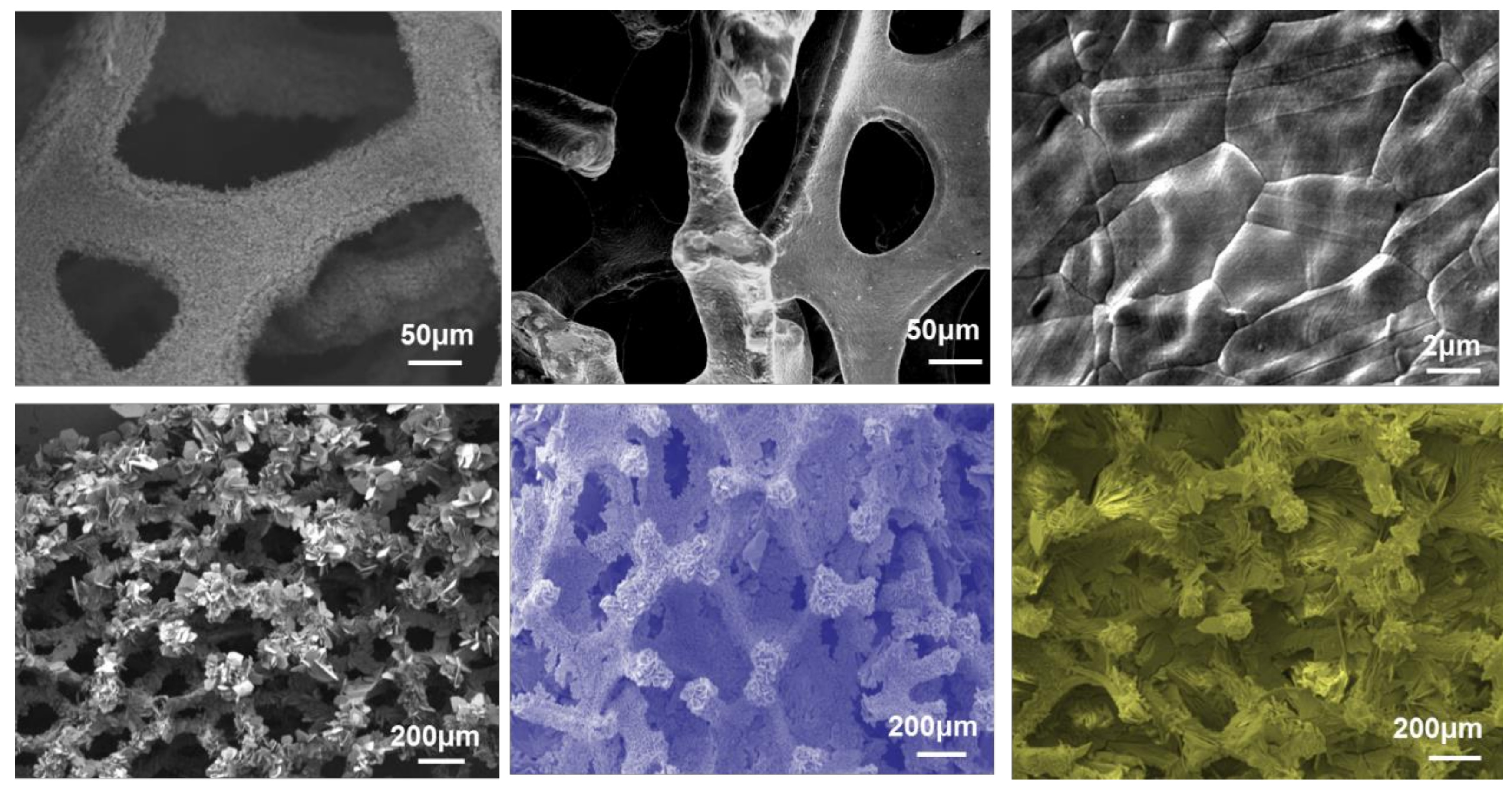
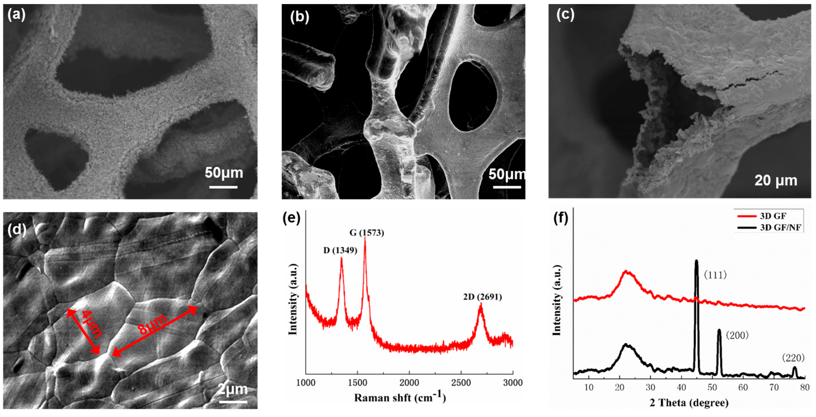
3.1. Structural Characterization of 3D GF

The GF was first fabricated via chemical vapor deposition (CVD) on a nickel foam (NF) substrate with methane gas as the carbon source. Briefly, the surface-cleaned NF sample was placed in a quartz tube. Under vacuum conditions, Ar, H2, and CH4 were alternately introduced by the volumetric ratio of 1:1:1. The obtained 3D graphene–nickel foam composites were then coated by polymethylmethacrylate (PMMA) solution. Subsequently, the NF template was chemically etched with a mixture of hot FeCl3–HCl. Finally, the obtained GF–PMMA composite was annealed at 450 °C for 2 h to remove PMMA using hot acetone. Figure 1a exhibits the SEM image of the NF scaffold with a pore size of 100–300 μm. The surface of the NF skeleton presents a rough morphology. The resulting 3D GF–NF composite exhibits continuous networks with a well inter-connected graphene coating over the NF micro-branches; this porous composite presents good structural robustness and high porosity (see Figure 1b). After completely etching the nickel and PMMA, the resulting pure GF maintains the original morphologies of NF with robust structure and consists of hollow branches. The few-layered graphene sheet grown conformably along with the original waved NF morphologies show flake-like features by the average size of 4 × 8 μm (see Figure 1d).
The structures of both GF and GF–NF are further characterized by Raman and XRD. As shown in Figure 1e, the intensive peak of D-band and relatively high D-band to G-band ratio (ID/IG ≈ 0.75) for Raman test demonstrate that the CVD synthesized 3D GF has high quality and a non-trivial amount of defects [20]. In addition, the sharp peak of 2G-band indicates a few-layered structure of GF [20]. Figure 1f shows the XRD results of the GF before and after etching the nickel substrate. Before the etching of the NF template, typical peaks are observed at positions of 44.6°, 52.3°, and 76.8°, corresponding to the characteristic diffraction peaks of the nickel metal (JCPDS NO. 78-0643), respectively [21,22]. After etching the nickel template, there are no nickel metal-related peaks appeared, indicating that the NF has been completely removed. The single peak on GF at 24° indicates the existence of pure 3D GF [22]. Comparing to those of state-of-the-art graphene monoliths prepared via hydrothermal or self-assembly, the CVD-fabricated GF has the same outstanding mechanical and pliable properties, and even better electrical conductivity due to well-interconnected scaffolds and low defects graphene sheets [23,24].

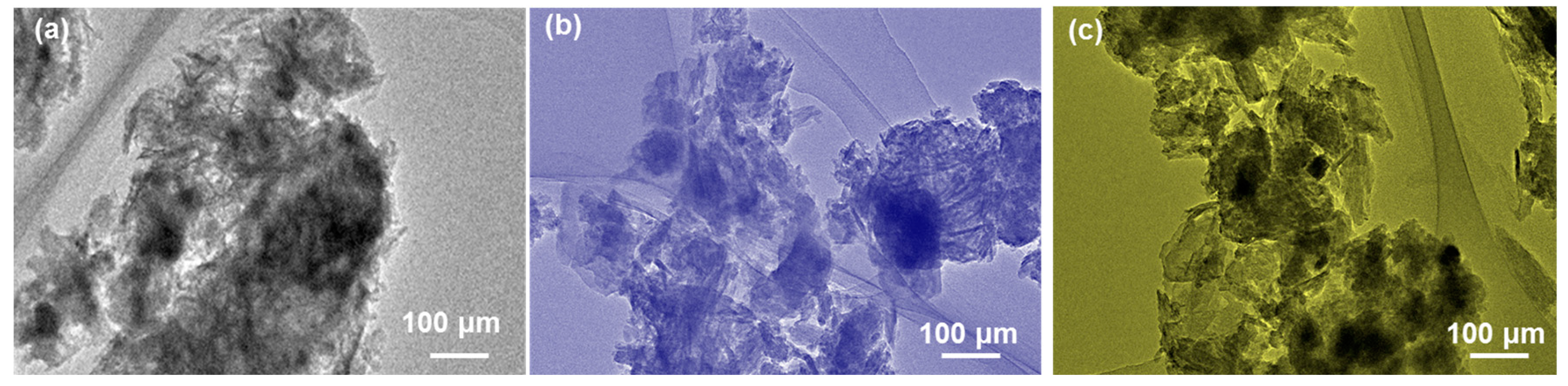
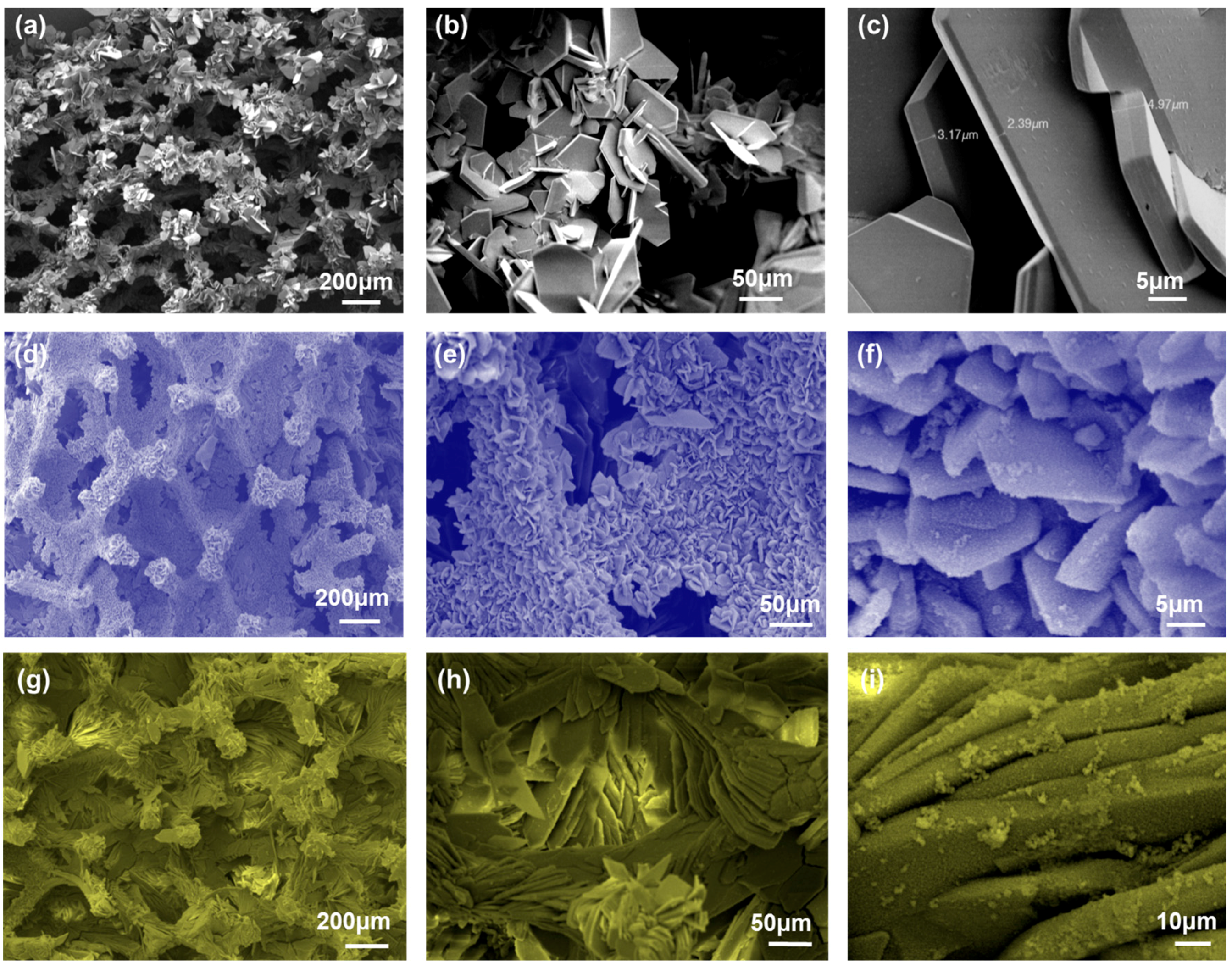
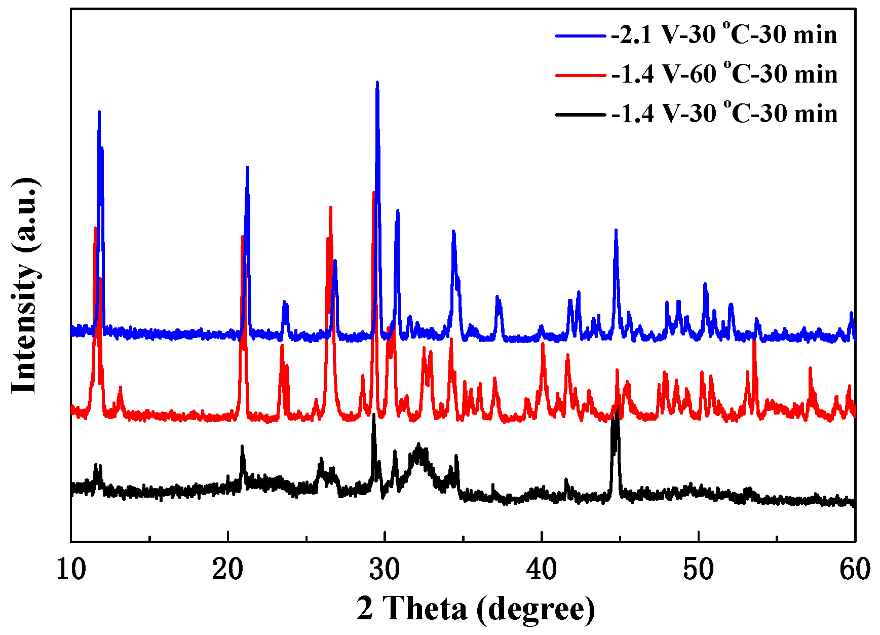
3.2. Mineralizing Evolution of GHBs Microstruture and Chemical Compostion
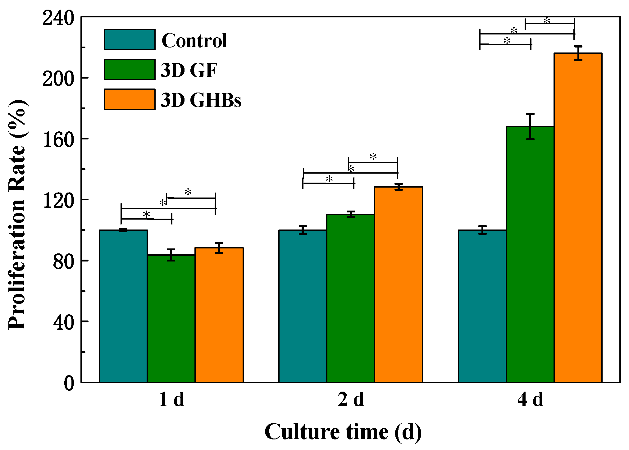
As shown in Figure 2a–c, the surface of the GF scaffold was mineralized with electrodepositing conditions of −1.4 V and 30 °C for 30 min. The related SEM images at different scale bars (200, 50, and 5 μm, respectively) show that the CP composite is conformably covered on the surface of micro-branches within the GF substrate. Although the pore size of GF is slightly reduced, there is no hole-blocking phenomenon that occurred. The high magnification image demonstrates the lamellar-featured structure of the CP composite on multiscale with the average thickness of 3.6 ± 0.5 μm and the diameter of several tens of millimeters. In addition, the effect of electrodepositing conditions on the morphologies of CP composite was further investigated at different temperature of 60 °C (−1.4 V/60° C for 30 min), as illustrated in Figure 2d–f. Interestingly, besides the same uniform and laminar deposition of CP composite, there are significant differences of the morphologies with more regular and smaller grain size appeared, leading to further increases of density and toughness for the mineralized GF.
As another influencing factor for electrochemical deposition, the voltage value also affects the morphology of the CP composite. The comparing case under the conditions of −2.1 V and 30 °C for 30 min shows similar lamellar structure, but the size of the CP grain is tending to be more uniform (about 70–80 μm) than those of other two cases (see Figure 2h–i). The mechanism for CP morphologies depending on mineralization conditions is because the larger cathode constant voltage and the current density can promote the growth of calcium and phosphorus crystals. Such performance can offer a novel way to mediate the structural morphology of the mineralized coating by adjusting the conditions of electrodeposition, facilitating controllable fabrication of CP mineralization with the expected prior properties. In addition, as shown in Figure 3a–c, the TEM images show that the CP composites possess flaky micrograph with laminar-like crystal structures by different sizes, which is consistent with the results obtained by SEM characterizations as demonstrated in Figure 2.
Furthermore, XRD was also utilized to characterize the crystal properties of the CP composite, which is coated on the surface of GF scaffold though electrochemical depositions, as shown in Figure 4. For each electrodeposition condition, a broad peak presents between the 2θ angles of 15° to 30° in the XRD data. However, it is not obvious for case of −1.4 V/60 °C and −2.1 V/30 °C, because the diffraction peaks of the CP composite are too strong to mask that of the graphene. The related peaks for CP composite are at 25.87°, 32.19°, 34.05°, and 50.49°, respectively, which are consistent with hydroxyapatite (HA) standard peaks (002), (112), (202), and (321) corresponding to JPCDS: 09-0432 [25]. The 2θ angles peaked at 25.85°, 29.22°, 30.74°, and 32.32° are consistent with octacalcium phosphate (OCP) standard peaks (−421), (−330), (6−11), and (−222) (JPCDS: 79-0423) [24], while the 2θ angle centered at 32.75° and 34.21° agrees with tricalcium phosphate (TCP) standard peaks (190) and (290) (JPCDS: 29-0359) [26]. In general, the CP composite obtained by electrodeposition under such condition is a mixture of OCP, TCP, and HA. Comparatively, the CP crystal properties deposited at different temperature (60 °C) and voltage (−2.1 V) were validated by XRD results (Figure 2c) with the number of peaks and related intensity greatly increased. Thereinto, the maximum peak of CP deposition formed at 60 °C indicates better crystallinity. Both OCP and TCP are considered as the precursors of HA formation, especially as OCP displays an essential role as biological salts in bone and teeth tissues. Previous studies have shown that OCP and TCP can transition to HA during the process of regulating local pH from acidic to alkaline [27]. Therefore, the change of pH value around the cathode electrode can cause supersaturation of the solution, leading to deposition of CP [28]. In this experiment, it is validated that the electrochemical deposition method can be used to prepare high purity calcium and phosphorus composites (e.g., OCP, dicalcium phosphate (DCP), and HA) on the surface of 3D GF by uniformly coated deposition.

3.3. MTT Assay

Biologically, HA can promote the integration of biomaterials with surrounding bone tissue; the 3D GHBs prepared at −1.4 V/60 °C for 30 min were used for further cytological detection. The cell viability and proliferation rate of MC3T3-E1 osteoblasts on the surface of 3D GF and 3D GHB scaffolds were evaluated by MTT assay. The MTT concerns and quantifies the biocompatibility and/or cytotoxicity, which is normally needed for 96 h (4 days) to get the final evaluation. Briefly, MC3T3-E1 was firstly cultured at 37 °C and 5 % CO2, and GF and GHB samples with a size of 8.0 × 8.0 × 1.6 mm3 were irradiated with ultraviolet light for 24 h. The MC3T3-E1 cells (105 cells/well) were then added to the 24-well culture plates and co-cultured with the scaffold materials. Eventually, the blue-violet crystals were completely shaken with the absorbance of each well measured by a microplate reader at a wavelength of 490 nm. As shown in Figure 5, on the 1st day of co-culture, the cell proliferation was slightly inhibited as compared with the control group. On 2nd day, the number of cells increased significantly, indicating both scaffolds without early cytotoxicity. On the 4th day, the enhancement rates of MC3T3 osteoblasts on the surface of the two scaffolds were 1.68 and 2.16 times higher than that of the control group, respectively. Moreover, the number of cells on the surface of the GHB scaffolds is higher than that of the GF scaffolds throughout the incubation period (except for the 1st day), which reveals the crucial role of CP composite (OCP, TCP, and HA) in regulating cell proliferation. Besides this, the dimension is another possible reason to influence the cell amount, which reveals the necessity to construct the 3D GF and GHBs for tissue regeneration engineering.

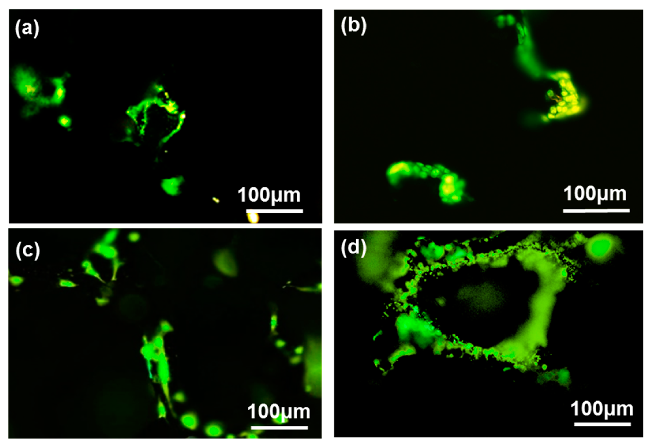
3.4. Acridine Orange–Ethidium Bromide (AO–EB) Double Staining

The health status and cytostatic activity of MC3T3-E1 cells were evaluated by acridine orange–ethidium bromide (AO–EB) double staining assay. Studies have shown that AO reagents can only penetrate into the living cells with the fluorescence appearing as green color, while EB only penetrates into dead cells to be orange-red [29]. Figure 6 shows the AO–EB staining fluorescence images of MC3T3-E1 cells co-cultured on 2nd day and 4th day, where the cells in the all pictures are almost green. The number of cells within both 3D GF and GHBs increase with the prolongation of culture time (2–4 d). Comparatively, the 3D GHBs demonstrate the higher densities of cells on the surface than that of the GF throughout the whole incubation period, which is consistent with the MTT results. Such prior performance validates that both kinds of scaffolds do not have cytotoxicity and can offer compatible substrate for cell adhesions. Therefore, it is necessary to show that 3D GHBs are more capable of promoting the proliferation of MC3T3-E1 cells.

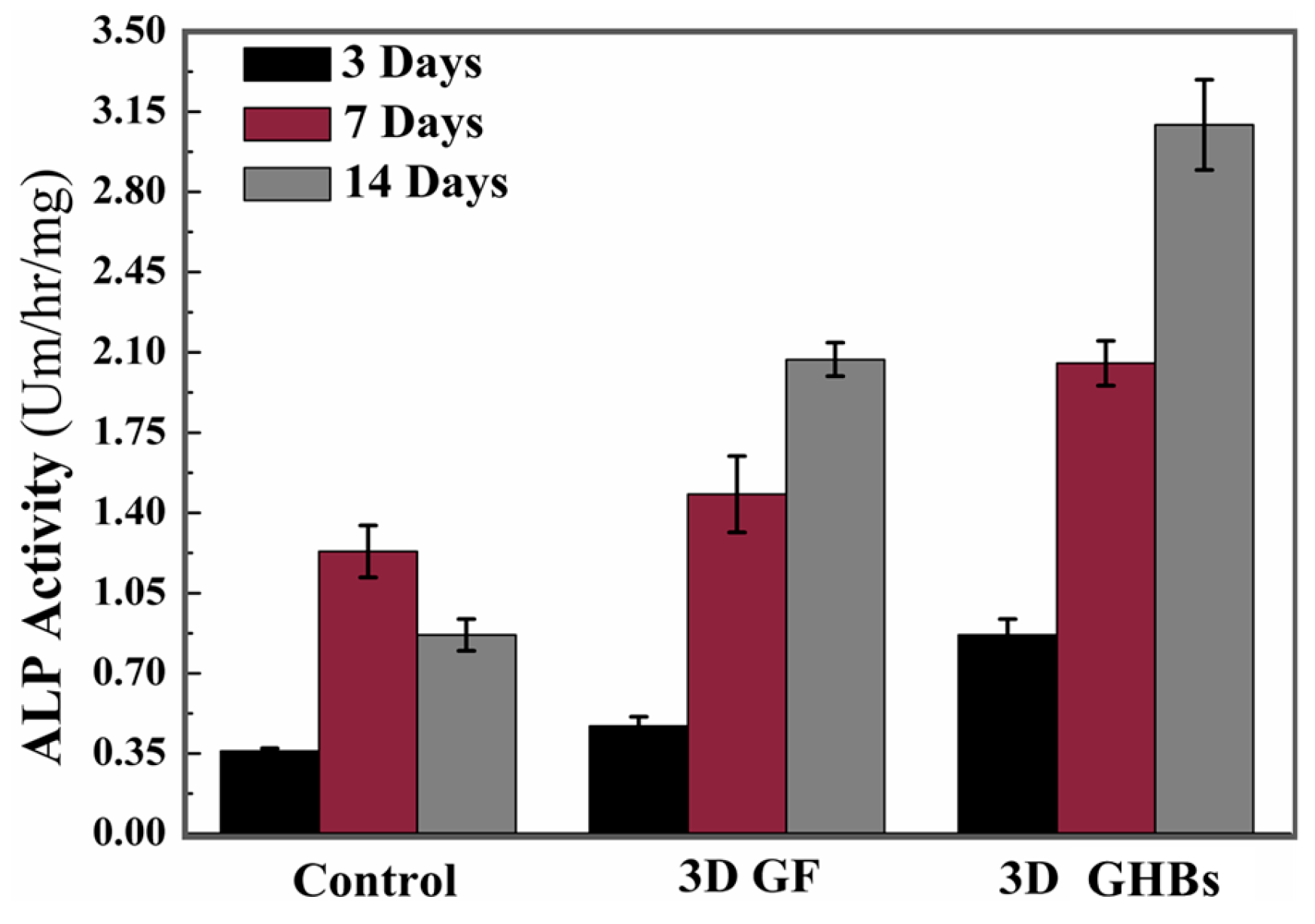
3.5. Alkaline Phosphatase (ALP) Experiments

The osteogenic differentiation ability of the graphene scaffold before and after mineralization was evaluated though the alkaline phosphatase (ALP) experiment, which was performed on 3rd, 7th, and 14th days. In detail, each hole was added with 150 μL of 0.05% Triton-X and implemented cyclic freeze-thaw processes. A mixture of substrate buffer solution and sample was added onto a 96-hole plate to incubate for 15 min at 37 °C. After reaction stop solution was added, the absorbance at 405 nm for finial uniform sample was measured. As shown in Figure 7, the ALP activity of MC3T3-E1 cells on the surface of both kinds of graphene-based scaffolds (3D GF and GHBs) before and after mineralization increases gradually, except for the control group (p < 0.05). At the 7th day after cell implantation, the 3D GHBs have higher ALP activity than that of the GF and control groups, which become more significant on the 14th day (p < 0.05). Those results showed that GHBs could induce the differentiation of osteoblasts MC3T3-E1 into mature osteoblasts, because the mineral salt coating promotes MC3T3-E1 cells to differentiate into osteoblasts in vitro.

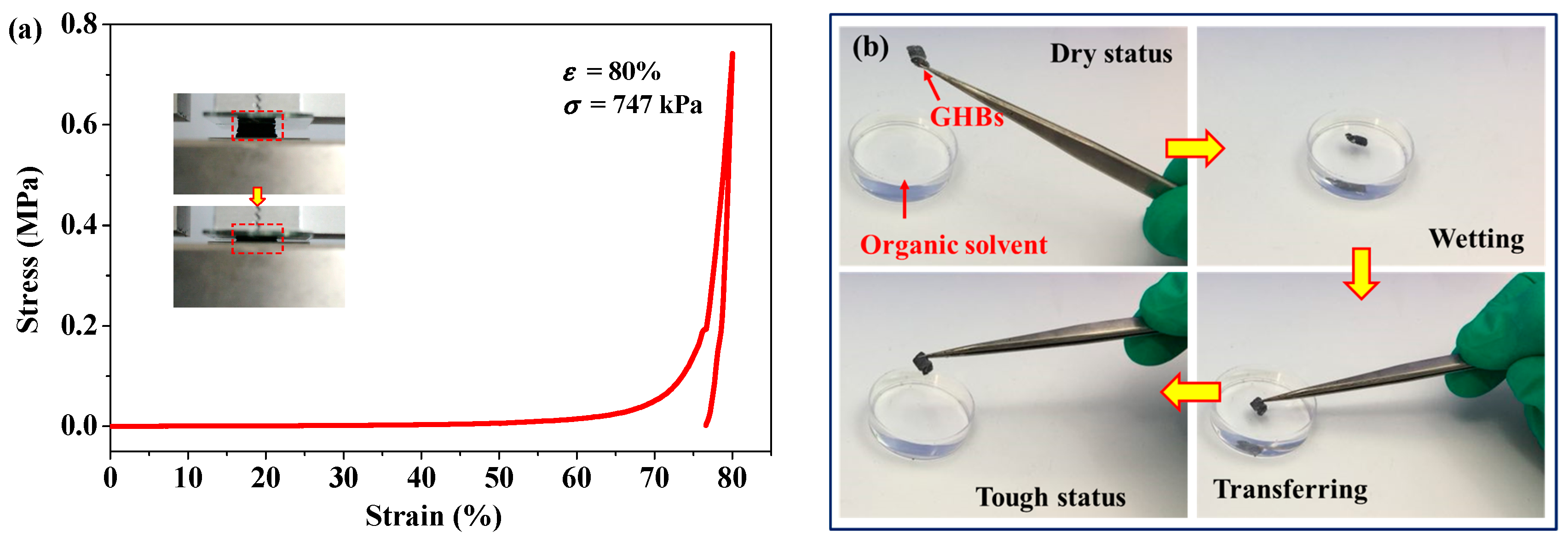
3.6. Mechanially Robust Performance

As shown in Figure 8a, the GHB sample was loaded by with a compression strain up to 80%. The strain vs. stress curve presents non-linear elastic deforming mechanism during compression. The highly porous GHB sample can be compressed into a thin ‘pancake’ with maximum strength up to 747 kPa corresponding to the compressive strain of 80% (see Inset of Figure 8a). Then, the compacted GHB scaffold recovers back to its original porous status, indicating an excellent robustness for structure undergoing a large-scale deformation. Comparatively, as the CP composite coated on GF template after the mineralizing process, the as-obtained GHB sample exhibits significantly increased strength and toughness with effective Young’s modulus of 0.933 MPa, which is over two orders higher than that of GF (~7.5 kPa) [16]. Moreover, as the promising bioscaffolds for cell attaching and creeping, the GHBs are required to not only possess a good mechanical elasticity, but also have tough capability maintaining structural stability during cultivation-transfer processes. As shown in Figure 8b, the original dry and stiff GHB sample was wetted in culture solvent, then transferred away with the structure keeping tough and robust. Such superior performance of GHBs resisting large deformation and tension-force-induced shrinkage enables them to be used widely as bio-compatible scaffolds.

4. Conclusions

In this article, we highlight the hydroxyapatite–calcium phosphate (HCP) salt coating on the surface of 3D GF by electrochemical deposition. The crystal morphologies of the mineral salt can be adjusted by changing the reaction temperature (e.g., 30 and 60 °C) and the applied voltage (e.g., −1.4 and −2.1 V). In particular, the mineral HCP salts obtained at the higher temperature present smaller and more uniform crystal grains. The as-obtained GHBs present highly robust structure under large compressing deformation or wetting processing in culture solvent. In addition, co-culture with MC3T3-E1 cells shows good biocompatibility of both 3D GF and GHBs. In particular, 3D GHBs can promote the proliferation of MC3T3-E1 osteoblasts, which is 2.16 times that of the control group on the 4th day, which is better than the 3D GF group and the control group. The combination of biocompatibility and bone conduction properties suggests promising application of 3D GHBs as a multifunctional material for stereoscopic bio-scaffold cultivation, implantable organ, bone tissue repair, and skin healing to those of clinical patients suffering with soft tissue deformities, congenital disability, comminuted fracture injury, burning hurt, etc.

Acknowledgments

The authors gratefully appreciate financial support from the Natural Science Foundation of China (81571829, 11472119, 11421062, 51702142), the Medical Subject Fund of Stomatology College of Lanzhou University (201502-3), the Fundamental Research Funds for the Central Universities (lzujbky-2015-293, lzujbky-2017-k17), and the open project of State Key Laboratory of Solid Lubrication, Lanzhou Institute of Chemical Physics, Chinese Academy of Sciences (LSL-1505).

Author Contributions

Jizeng Wang and Qiangqiang Zhang conceived and designed the experiments; Weibo Jie and Fuxiang Song performed the experiments; Rui Wang analyzed the data; Shenglin Sun and Miao Li contributed analysis tools; Zengjie Fan and Bin Liu made critical revisions to the article.

Conflicts of Interest

The authors declare no conflict of interest.

References

  1. Mao, J.J.; Stosich, M.S.; Moioli, E.K.; Lee, C.H.; Fu, S.Y.; Bastian, B.; Eisig, S.B.; Zemnick, C.; Ascherman, J.; Wu, J. Facial reconstruction by biosurgery: Cell transplantation versus cell homing. Tissue Eng. Part B Rev. 2010, 16, 257–262. [Google Scholar] [CrossRef] [PubMed]
  2. Xu, T.; Yang, H.Y.; Yang, D.Z.; Yu, Z.Z. Polylactic acid nanofiber scaffold decorated with chitosan islandlike topography for bone tissue engineering. ACS Appl. Mater. Interfaces 2017, 9, 21094–21104. [Google Scholar] [CrossRef] [PubMed]
  3. Baino, F.; Novajra, G.; Miguez-Pacheco, V.; Boccaccini, A.R.; Vitale-Brovarone, C. Bioactive glasses: Special applications outside the skeletal system. J. Non-Cryst. Solids 2016, 432, 15–30. [Google Scholar] [CrossRef]
  4. Gomez-Lizarraga, K.K.; Flores-Morales, C.; Del Prado-Audelo, M.L.; Alvarez-Perez, M.A.; Pina-Barba, M.C.; Escobedo, C. Polycaprolactone- and polycaprolactone/ceramic-based 3D-bioplotted porous scaffolds for bone regeneration: A comparative study. Mater. Sci. Eng. C Mater. 2017, 79, 326–335. [Google Scholar] [CrossRef] [PubMed]
  5. Lu, J.; Cheng, C.; He, Y.S.; Lyu, C.; Wang, Y.; Yu, J.; Qiu, L.; Zou, D.; Li, D. Multilayered Graphene Hydrogel Membranes for Guided Bone Regeneration. Adv. Mater. 2016, 28, 4025–4031. [Google Scholar] [CrossRef] [PubMed]
  6. Nie, W.; Peng, C.; Zhou, X.; Chen, L.; Wang, W.; Zhang, Y.; Ma, P.X.; He, C. Three-dimensional porous scaffold by self-assembly of reduced graphene oxide and nano-hydroxyapatite composites for bone tissue engineering. Carbon 2017, 116, 325–337. [Google Scholar] [CrossRef]
  7. Li, N.; Zhang, Q.; Gao, S.; Huang, R.; Wang, L.; Liu, L.; Dai, J.; Tang, M.; Cheng, G. Three-dimensional graphene foam as a biocompatible and conductive scaffold for neural stem cells. Sci. Rep. 2013, 3, 1604. [Google Scholar] [CrossRef] [PubMed]
  8. Crowder, S.W.; Prasai, D.; Rath, R.; Balikov, D.A.; Bae, H.; Bolotin, K.I.; Sung, H.J. Three-dimensional graphene foams promote osteogenic differentiation of human mesenchymal stem cells. Nanoscale 2013, 5, 4171–4176. [Google Scholar] [CrossRef] [PubMed]
  9. Li, Z.; Wang, H.; Yang, B.; Sun, Y.; Huo, R. Three-dimensional graphene foams loaded with bone marrow derived mesenchymal stem cells promote skin wound healing with reduced scarring. Mater. Sci. Eng. C 2015, 57, 181–188. [Google Scholar] [CrossRef] [PubMed]
  10. Krueger, E.; Chang, A.N.; Brown, D.; Eixenberger, J.; Brown, R.; Rastegar, S.; Yocham, K.M.; Cantley, K.D.; Estrada, D. Graphene foam as a three-dimensional platform for myotube growth. ACS Biomater. Sci. Eng. 2016, 2, 1234–1241. [Google Scholar] [CrossRef] [PubMed]
  11. Ameri, S.K.; Singh, P.K.; D’Angelo, R.; Stoppel, W.; Black, L.; Sonkusale, S.R. Three dimensional graphene scaffold for cardiac tissue engineering and in-situ electrical recording. In Proceedings of the 2016 IEEE 38th Annual International Conference of the Engineering in Medicine and Biology Society (EMBC), Orlando, FL, USA, 16–20 August 2016; pp. 4201–4203. [Google Scholar]
  12. Ishack, S.; Mediero, A.; Wilder, T.; Ricci, J.L.; Cronstein, B.N. Bone regeneration in critical bone defects using three-dimensionally printed beta-tricalcium phosphate/hydroxyapatite scaffolds is enhanced by coating scaffolds with either dipyridamole or BMP-2. J. Biomed. Mater. Res. B 2017, 105, 366–375. [Google Scholar] [CrossRef] [PubMed]
  13. Quinlan, E.; Lopez-Noriega, A.; Thompson, E.; Kelly, H.M.; Cryan, S.A.; O’Brien, F.J. Development of collagen-hydroxyapatite scaffolds incorporating PLGA and alginate microparticles for the controlled delivery of rhBMP-2 for bone tissue engineering. J. Control. Release 2015, 198, 71–79. [Google Scholar] [CrossRef] [PubMed]
  14. Quinlan, E.; Lopez-Noriega, A.; Thompson, E.M.; Hibbitts, A.; Cryan, S.A.; O’Brien, F.J. Controlled release of vascular endothelial growth factor from spray-dried alginate microparticles in collagen-hydroxyapatite scaffolds for promoting vascularization and bone repair. J. Tissue Eng. Regen. Med. 2017, 11, 1097–1109. [Google Scholar] [CrossRef] [PubMed]
  15. Hu, X.B.; Liu, Y.L.; Wang, W.J.; Zhang, H.W.; Qin, Y.; Guo, S.; Zhang, X.W.; Fu, L.; Huang, W.H. Biomimetic graphene-based 3D scaffold for long-term cell culture and real-time electrochemical monitoring. Anal. Chem. 2018, 90, 1136–1141. [Google Scholar] [CrossRef] [PubMed]
  16. Zhang, Q.; Zhang, B.; Yu, Y.; Zhao, K.; He, P.; Huang, B. Fluoroalkyl-silane-modified 3D graphene foam with improved Joule-heating effects and high hydrophobicity-derived anti-icing properties. J. Mater. Sci. 2018, 53, 528–537. [Google Scholar] [CrossRef]
  17. Bakin, B.; Koc Delice, T.; Tiric, U.; Birlik, I.; Ak Azem, F. Bioactivity and corrosion properties of magnesium-substituted CaP coatings produced via electrochemical deposition. Surf. Coat. Technol. 2016, 301, 29–35. [Google Scholar] [CrossRef]
  18. Đošić, M.; Eraković, S.; Janković, A.; Vukašinović-Sekulić, M.; Matić, I.Z.; Stojanović, J.; Rhee, K.Y.; Mišković-Stanković, V.; Park, S.J. In vitro investigation of electrophoretically deposited bioactive hydroxyapatite/chitosan coatings reinforced by graphene. J. Ind. Eng. Chem. 2017, 47, 336–347. [Google Scholar] [CrossRef]
  19. Nardecchia, S.; Serrano, M.C.; Gutiérrez, M.C.; Portolés, M.T.; Ferrer, M.L.; del Monte, F. Osteoconductive performance of carbon nanotube scaffolds homogeneously mineralized by flow-through electrodeposition. Adv. Funct. Mater. 2012, 22, 4411–4420. [Google Scholar] [CrossRef]
  20. She, X.; Sun, P.; Yu, X.; Zhang, Q.; Wu, Y.; Li, L.; Huang, Y.; Shang, S.; Jiang, S. Fabrication of 3D polypyrrole/graphene oxide composite hydrogels with high performance swelling properties. J. Inorg. Organomet. Polym. 2014, 24, 884–889. [Google Scholar] [CrossRef]
  21. Shivakumara, S.; Kishore, B.; Penki, T.R.; Munichandraiah, N. Symmetric supercapacitor based on reduced graphene oxide in non-aqueous electrolyte. ECS Electrochem. Lett. 2015, 4, A87–A89. [Google Scholar] [CrossRef]
  22. Trung, N.B.; Tam, T.V.; Dang, D.K.; Babu, K.F.; Kim, E.J.; Kim, J.; Choi, W.M. Facile synthesis of three-dimensional graphene/nickel oxide nanoparticles composites for high performance supercapacitor electrodes. Chem. Eng. J. 2015, 264, 603–609. [Google Scholar] [CrossRef]
  23. Hu, H.; Zhao, Z.; Wan, W.; Gogotsi, Y.; Qiu, J. Ultralight and highly compressible graphene aerogels. Adv. Mater. 2013, 25, 2219–2223. [Google Scholar] [CrossRef] [PubMed]
  24. Zhang, Q.; Lin, D.; Deng, B.; Xu, X.; Nian, Q.; Jin, S.; Leedy, K.; Li, H.; Cheng, G.J. Flyweight, Superelastic, electrically conductive, and flame-retardant 3D multi-nanolayer graphene/ceramic metamaterial. Adv. Mater. 2017, 29, 1605506. [Google Scholar] [CrossRef] [PubMed]
  25. Anwar, A.; Kanwal, Q.; Akbar, S.; Munawar, A.; Durrani, A.; Hassan Farooq, M. Synthesis and characterization of pure and nanosized hydroxyapatite bioceramics. Nanotechnol. Rev. 2017, 6. [Google Scholar] [CrossRef]
  26. Mohammadi, Z.; Sheikh−Mehdi Mesgar, A.; Rasouli-Disfani, F. Preparation and characterization of single phase, biphasic and triphasic calcium phosphate whisker-like fibers by homogenous precipitation using urea. Ceram. Int. 2016, 42, 6955–6961. [Google Scholar] [CrossRef]
  27. Ito, N.; Kamitakahara, M.; Yoshimura, M.; Ioku, K. Importance of nucleation in transformation of octacalcium phosphate to hydroxyapatite. Mat. Sci. Eng. C Mater. 2014, 40, 121–126. [Google Scholar] [CrossRef] [PubMed]
  28. Nam, P.T.; Lam, T.D.; Huong, H.T.; Phuong, N.T.; Thu Trang, N.T.; Hoang, T.; Thanh Huong, N.T.; Thang, L.B.; Drouet, C.; Grossin, D.; et al. Electrodeposition and characterization of hydroxyapatite on TiN/316LSS. J. Nanosci. Nanotechnol. 2015, 15, 9991–10001. [Google Scholar] [CrossRef] [PubMed]
  29. Simić, V.; Kolarević, S.; Brčeski, I.; Jeremić, D.; Vuković-Gačić, B. Cytotoxicity and antiviral activity of palladium(II) and platinum(II) complexes with 2-(diphenylphosphino)benzaldehyde 1-adamantoylhydrazone. Turk. J. Biol. 2016, 40, 661–669. [Google Scholar] [CrossRef]
Figure 1. The microstructural characterizations. (a) SEM micrographs of nickel foam NF. (b) 3D GF/NF composite. (c) GF consisting of hollow micro-branches after NF and PMMA etching. (d) The flake-like graphene coverage. (e) The Raman spectrum of GF. (f) The comparative XRD patterns of GF and GF/NF composite. NF, nickel foam; GF, graphene foam; PMMA, polymethylmethacrylate.
Crystals 08 00105 g001
Figure 2. SEM images of graphene–hydroxyapatite hybrid bioscaffolds (GHBs) for different electrodeposition conditions. (ac) 30 °C and −1.4 V for 30 min. (df) 60 °C and −1.4 V for 30 min. (gi) 30 °C and −2.1 V for 30 min.
Crystals 08 00105 g002
Figure 3. TEM micrographs of GHBs with similar deposition conditions. (a) 30 °C and −1.4 V for 30 min. (b) 60 °C and −1.4 V for 30 min. (c) 30 °C and −2.1 V for 30 min.
Crystals 08 00105 g003
Figure 4. The comparative XRD results of electrochemical disposition of the calcium phosphate (CP) composite on GF under different fabrication conditions.
Crystals 08 00105 g004
Figure 5. Comparison proliferation rate of the MC3T3-E1 cells after being cultured with 3D GF and GHB scaffold at 1, 2, and 4 d. Asterisk (*) indicates the significance with p < 0.05, and the error bar represents the standard deviation.
Crystals 08 00105 g005
Figure 6. Fluorescence microscope images of the MC3T3-E1 cells after acridine orange–ethidium bromide (AO–EB) double staining. (a) and (b) 2nd and 4th days on 3D GF, respectively. (c) and (d) 2nd and 4th days on 3D GHBs, respectively.
Crystals 08 00105 g006
Figure 7. Alkaline phosphatase (ALP) activity of MC3T3-E1 cells cultured on 3D GF and GHBs for 3rd, 7th, and 14th days, respectively.
Crystals 08 00105 g007
Figure 8. (a) The comparative mechanical compression test of GHB samples with maximum strain up to 80%. Inset is the snapshots during compression. (b) The validation of mechanical robustness of GHB sample during operation in solvent conditions.
Crystals 08 00105 g008

