Article

Morphological and Crystallographic Characteristics of α Structure in a Low-Carbon Iron–Nickel Alloy

1
State Key Laboratory of Advanced Processing and Recycling of Non-ferrous Metals, Lanzhou University of Technology, Lanzhou 730050, China
2
Department of Materials Science and Engineering, Lanzhou University of Technology, Lanzhou 730050, China
3
Laboratory of Thermo Mechanical Metallurgy (LMTM), PX Group Chair, Ecole Polytechnique Fédérale de Lausanne (EPFL), Rue de la Maladière 71b, 2000 Neuchâtel, Switzerland
4
Institute of Water Resources and Hydropower Research, Northwest A\&F University, Yangling 712100, China
*
Authors to whom correspondence should be addressed.
Crystals 2018, 8(12), 468; https://doi.org/10.3390/cryst8120468
Submission received: 29 November 2018 / Revised: 11 December 2018 / Accepted: 12 December 2018 / Published: 14 December 2018
(This article belongs to the Special Issue Microstructures and Properties of Martensitic Materials)

Abstract

:
The features of α (body-centered cubic) structures were investigated in a low-carbon multicomponent alloy from morphological and crystallographic perspectives. In addition to apparent features of granular bainite and lamellar martensite, a morphological similarity can be found between lath martensite and lath bainite. Therefore, it is of interest to explore possible discrepancies between lath martensite and lath bainite from a crystallographic perspective. These microstructures were obtained by various cooling rates (i.e., water quenching, 5 °C/s, and 0.05 °C/s) and then were characterized by a combination of scanning electron microscopy and electron backscattered diffraction techniques. It is shown that: (1) Lath martensite (LM) formed in the samples that were water-quenched, and a mixture of LM and lath bainite (LB) and granular bainite (GB) formed in the samples cooled at rates of 5 °C/s and 0.05 °C/s, respectively; (2) A Kurdjumov-Sachs relationship was mostly found in as-quenched martensite, while a Greninger-Troiano relationship represented the orientation relationship of LB and GB; (3) As the cooling rate decreased, the dislocation densities in corresponding microstructures were reduced, while the tendency of variant grouping was enhanced.

Graphical Abstract

1. Introduction

The most common mechanical properties of polycrystalline materials, i.e., strength, high toughness, long service life, and versatility, are sought in material innovation [1,2]. These properties are largely determined by the microstructure of a material, which often results from a phase transformation during the manufacturing process. In the case of a low-alloy ultra-high strength structural steel used for welding, the microstructure obtained in the heat-affected zone at low heat input (i.e., 10.5 kJ/cm) is constituted of lath martensite (LM) and lath bainite (LB), while that at higher heat input (18.5 kJ/cm) is granular bainite (GB) [3]. The microstructures in low-carbon high-strength weld metals are a mixture of LM, LB, and GB [4], and these three phases are all body-centered cubic (bcc) or tetragonal with similar morphologies and lattice parameters [5]. We tried to distinguish LM, LB, and GB by using crystallography. Indeed, each phase can have a specific effect on the mechanical properties of a metal.
Crystallographic information on the samples such as phase identification, grain orientations, misorientations across grain boundaries, etc. can be acquired by electron backscattered diffraction (EBSD). Abundant work has been conducted to introduce some crystallographic terminologies considering γ to α phase transformation in carbon steels. Table 1 presents various possible orientation relationships (ORs) between the γ parent phase and the α daughter phase [6], that is, Kurdjumov–Sachs (K-S) OR, Nishiyama–Wassermann (N-W) OR, Greninger-Troiano (G-T) OR, and Pitsch OR. In the manuscript, we will only consider the crystallographic orientation variants from a certain prior austenite crystal that are based on K-S ORs. In the K-S OR, there are four {111}γ planes, wherein each plane is parallel to a {110}α plane. A {111}γ plane contains three <110>γ directions, and each <110>γ direction is parallel to one of the two <111>α directions in the {110}α plane that is parallel to {111}γ. Finally, 24 K-S variants are generated [7]. These variants tend to be grouped to facilitate the deformation during phase transformation [8]. As such, regarding martensitic transformation, the specific variants are combined preferably to accommodate the transformation strains. Variant 1 (V1) was indexed as the largest bcc grain in a prior austenite grain (PAG). The Operators (O) are the specific misorientations between the variants. The notion was applied to correlate all variants [9], wherein V1 was always treated as a reference to define the operators. Therefore, local variant grouping can be detected by looking at the operator tendency. The operators between the variants with a K-S OR were detailed in earlier work [9]. Note that three types of packets have been widely accepted as having crucial roles in determining the macroscopic mechanical properties [9]. The close-packed-plane (CPP) packets are often regarded as morphological packets containing bainitic/martensitic ferrite laths with approximately the same trace on the sample surface because habit planes are close to each other [10]. The close-packed-direction (CPD) packets contain a collection of variants that share a common axis parallel to one direction [9]. The Bain packets (BP) are the assemblies of variants linked by low misorientations [11]. Different operators are included in these three packets, as shown in Table 2 [9]. In other words, different packets can be explicitly given as sets of variants and organized assemblies of operators.
The features of both martensitic microstructure and bainitic microstructure have been deeply explored in recent years [11,12,13,14]. For instance, Morito et al. proposed that the minimization of the total shape strain generated during martensitic transformation led to six variants in one CPP packet in alloy steels [12]. Lambert-Perlade et al. utilized a micromechanical model to evaluate the self-accommodation of the transformation for Bain packets in a low-alloy steel [13]. Cayron brought forward a one-step model of martensitic transformation to explain the crystallographic intricacy and the continuous orientations of martensite variants [11]. Takayama et al. revealed that bainitic ferrite variants were generated adjacently by sharing the same parallel relations for CPP packets [14]. Nevertheless, for some microstructures with similar morphologies, such as lath bainite and lath martensite, little attention has been paid to investigate their distinguishing features from a comprehensively crystallographic perspective, e.g., orientation relationships, boundary disorientation features, and variant groupings.
Therefore, this study aimed at adding a reliable proof to figure out the discrepancy among the different microstructures in a low-carbon iron-nickel alloy.

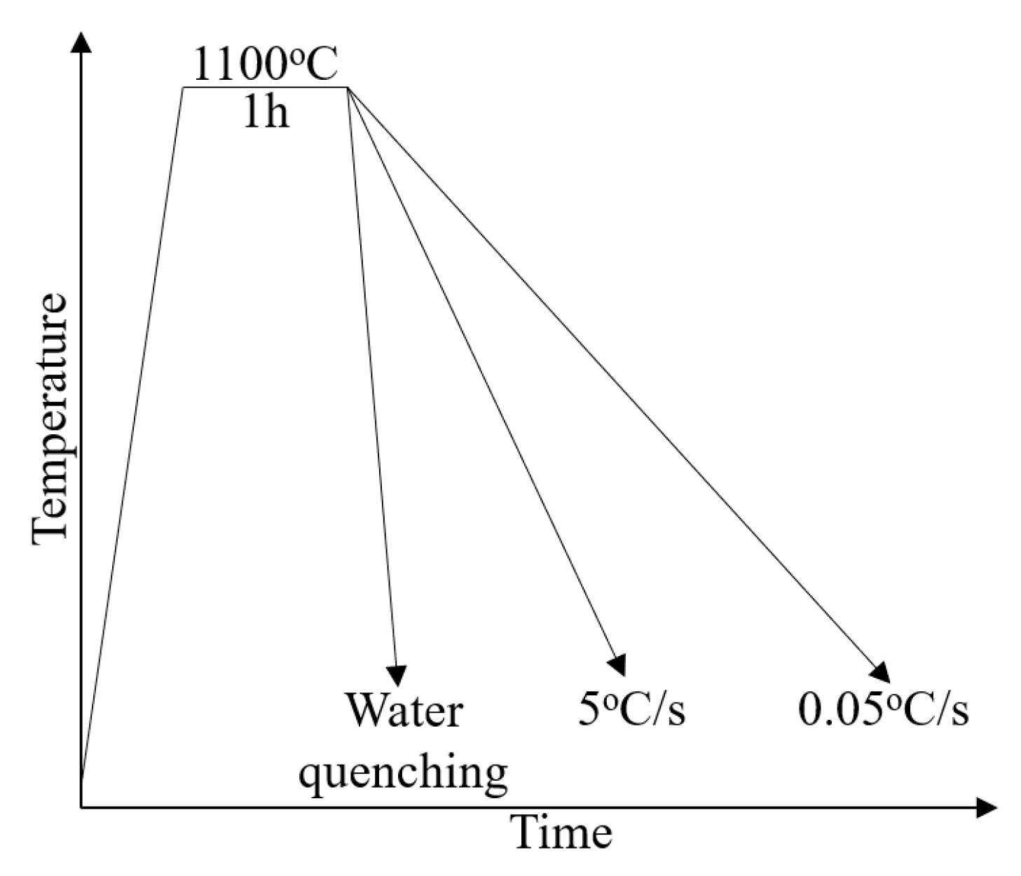
2. Materials and Methods

The raw materials, in this research, were obtained from low-carbon bainitic weld metals. The details are reported in Reference [7]. The composition here was 5Ni–0.05C–1.8Mn–0.3Si–0.8Mo–0.8Cr–0.001S–0.14Ti. Each specimen had the same size (10mm). They were put in quartz tubes under primary vacuum, heated to 1100 °C in a furnace (Nabartherm, Lilienthal, Germany), and then cooled at various rates (i.e., 0.05 °C/s, 5 °C/s, and water quenching), as shown in Figure 1.
The metallographic specimens were prepared by common methods (i.e., manual and mechanical polishing), and the microstructures were characterized using scanning electron microscope (SEM; FEI XL30 Series; Thermo Fisher Scientific, MA, USA). The EBSD specimens were prepared by finally polishing on a VibroMet™ (Buehler, IL, USA) table for several hours after previous mechanical polishing. The EBSD maps of all specimens were acquired over a 200 μm × 200 μm scan area using a 400 nm step size and analyzed with ARPGE software [15].

3. Results

The SEM and EBSD techniques were applied to display different features of α structures in our specimens from morphological and crystallographic perspectives.

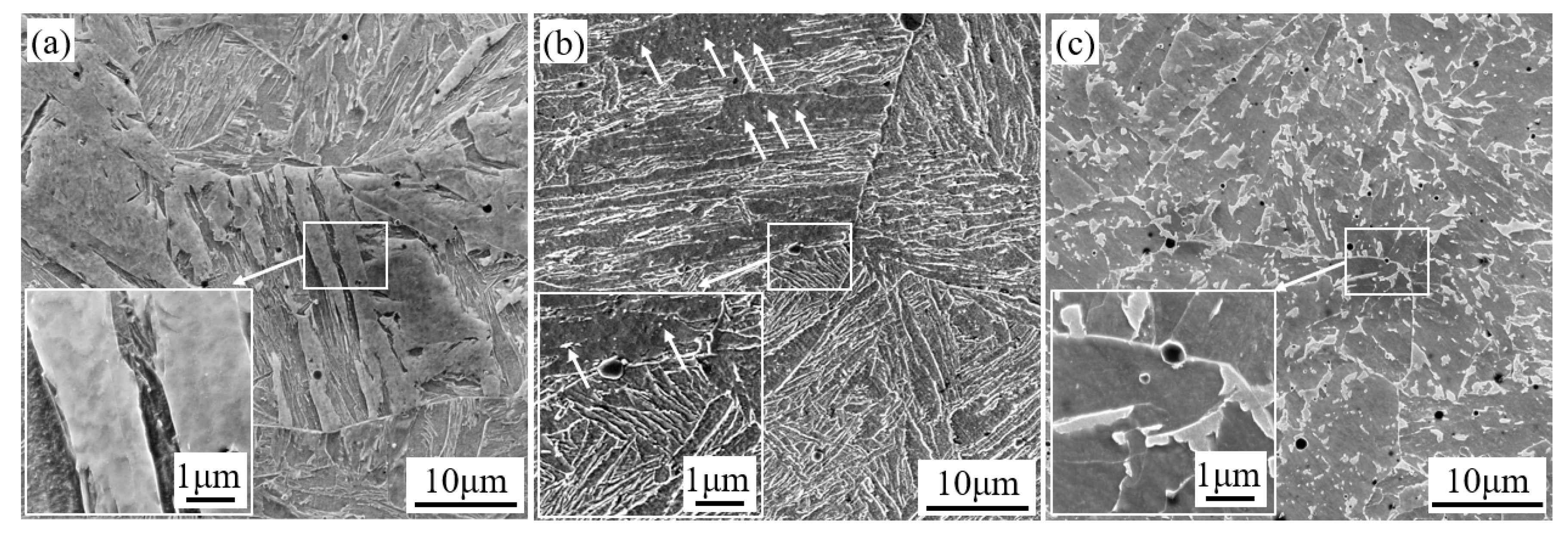
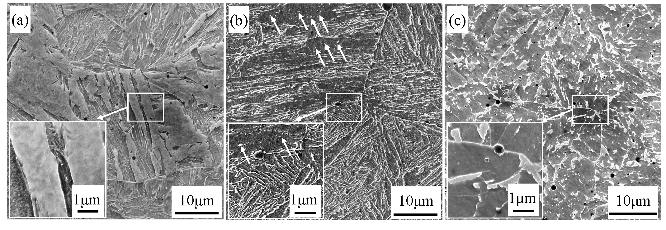
3.1. Morphologic Features

As depicted in Figure 2, there were three corresponding morphologies under various cooling conditions. The water-quenched specimen was constituted of martensite with a width range of 1–1.5 μm, typically plate-like, as shown at high magnification in Figure 2a. In the sample cooled at 5 °C/s, it was found that all laths were nucleated on the grain boundaries and extended towards the interior of the grains, as shown in Figure 2b. Besides, some dispersed carbides appeared in white in the lath ferritic grains, as indicated by the short arrows. It was somehow difficult to distinguish bainite and martensite on the basis of the morphology, because both sometimes appeared lath-like. Thus, it was necessary to perform a crystallographic analysis to find some clues regarding the differences between bainite and martensite. In Figure 2c, GB was obtained when the specimen was cooled at 0.05 °C/s. GB is indeed characterized by the absence of carbides and by the presence of isolated martensite-austenite (M-A) constituents [16]. M-A islands appear in grey and are distributed in the ferritic matrix that is dark in the SEM image shown. An image of M-A islands at higher magnification is inserted at the left bottom of Figure 2c. Some M-A islands were distributed along the grain boundary, and others were distributed randomly in one grain. In addition, the ratio between length and width of the M–A islands was around 2.

3.2. Crystallographic Features

The crystallographic features of each microstructure can be observed by means of EBSD. Figure 3a–c depict CPP packets in all specimens. In this figure, the region composed by variants belonging to the same CPP packet is represented by the same color. For a detailed analysis by EBSD, one single PAG was selected in each sample. The PAG boundaries were delineated in white. Note that the packets in fast-cooling samples (i.e., water quenching and 5 °C/s) had different sizes and irregular shapes. However, the CPP packets in slow-cooling samples (i.e., 0.05 °C/s) tended to be in blocky morphology. Figure 3d–f display the local strain distribution among phases in three samples by means of kernel average misorientation (KAM) color-coded maps. These maps were computed using a maximum misorientation of 5° and were averaged with the third neighbor misorientation, which provided a qualitative estimation of minor local strain gradients as plastic deformation [17]. Misorientations higher than 5° were excluded, because these misorientations are ascribed to the generation of low-angle misorientation grain boundaries. As depicted in Figure 3d–f, the average local misorientation angle ( θ ) decreased from θ = 0.99°, to 0.70°, to 0.69° as the cooling process varied from water quenching, to 5 °C/s, and to 0.05 °C/s, respectively.

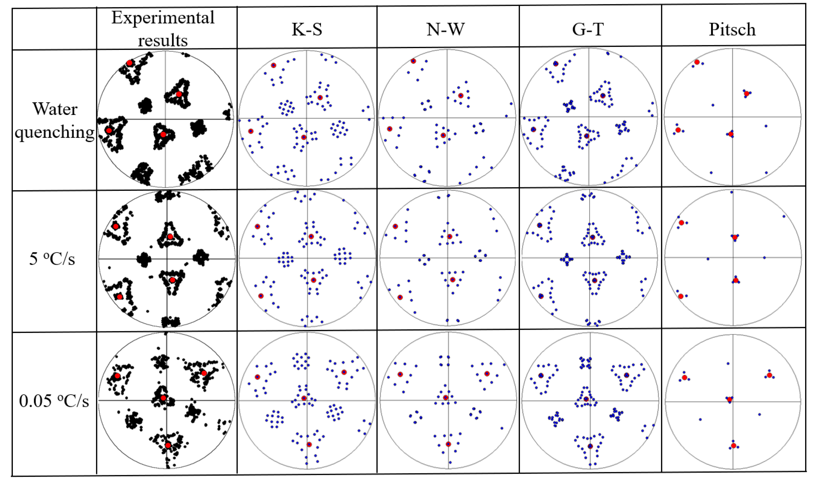
3.3. Orientation Relationships

The pole figures corresponding to the marked grains in Figure 3 are shown in Figure 4. They indicate the ORs of bainite and martensite. The experimental {011}bcc pole figures of the variants (black spots) inside a prior γ grain, whose calculated orientation is shown by the { 111 } γ poles (red spots), are given in the first column in Figure 4. Regardless of the cooling rate, the ORs of these sub-microstructures were closer to K-S and G-T ORs than to N-W and Pitsch ORs, as depicted in Figure 5b. K-S OR was the most extensive in as-quenched martensite, and G-T OR was at the highest frequency in GB obtained at 0.05 °C/s. The internal misorientations were more extended in the water-quenched alloy than in the other two samples, because of the higher dislocation content contained in martensite (Figure 5a).

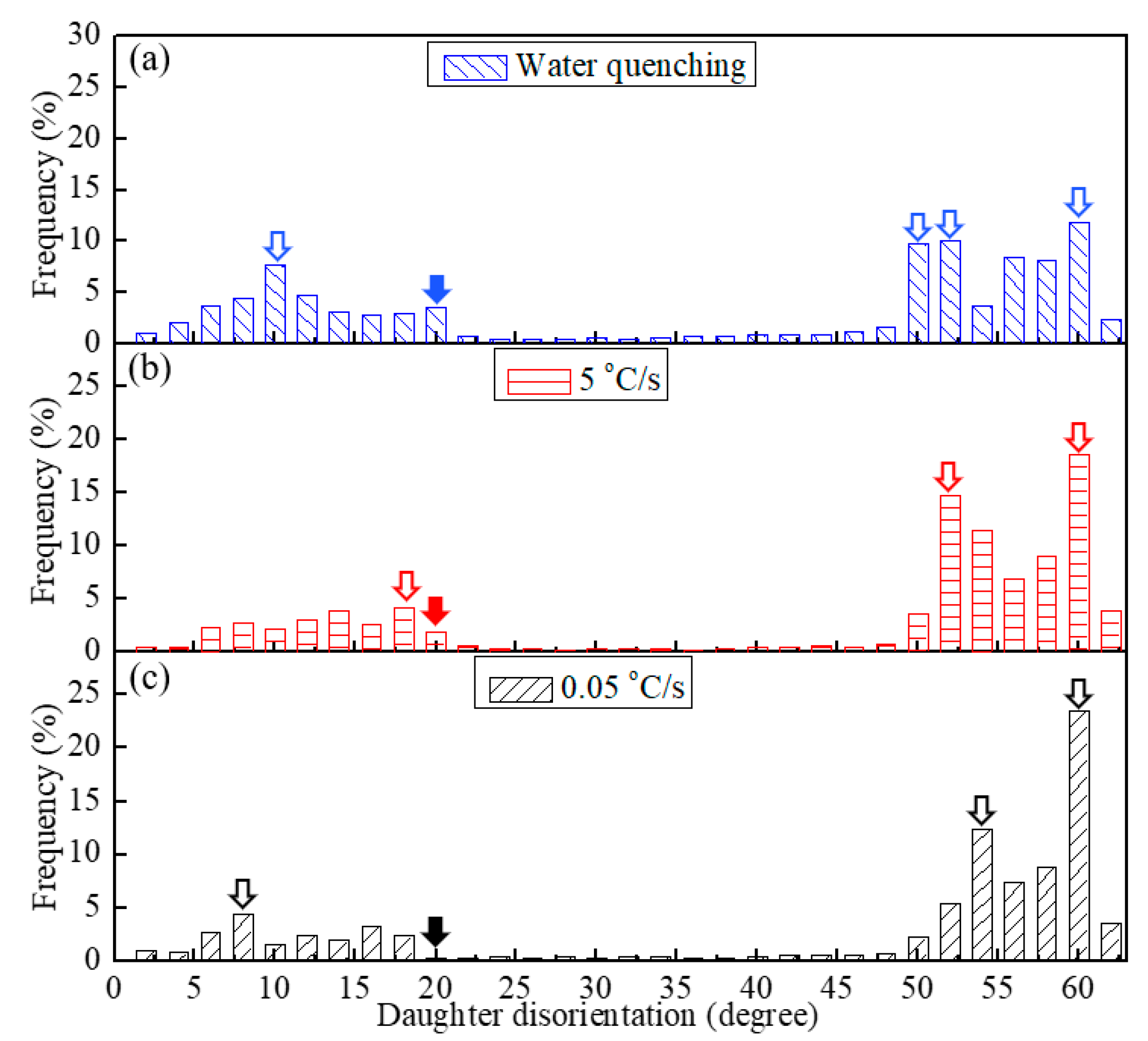
3.4. Boundary Disorienttaion Features

In addition to the CPP figures, KAM maps, and pole figures, boundary features such as disorientation angle distribution as well as variant grouping are properties useful to explore the microstructure characteristics and the transformation behavior. Figure 6a–c show the distributions of daughter grain boundary disorientation angles in three specimens. For each cooling process, a few characteristic similarities among the histograms could be detected. There was one common peak at the estimated misorientation angle of 60°, while the boundaries with the disorientation angle range between 22.5° and 47.5° were rarely be observed at any cooling rate. Likewise, there were some differences among the distributions. First, boundaries with the approximate disorientation angle of 10°, 20°, 50°, and 52.5° were found more frequently in the as-quenched specimen (blue hollow arrows in Figure 6a); two peaks at 18° and 52° were detected in the sample cooled at 5 °C/s (red hollow arrows in Figure 6b), while two peaks at 9° and 54.5° were detected in the sample cooled at 0.05 °C/s (black hollow arrows in Figure 6c). Moreover, the height of the peak at 60° seemed to be affected by the cooling procedures, that is, the peak height at 60° tended to increase with the reduction of the cooling rate.

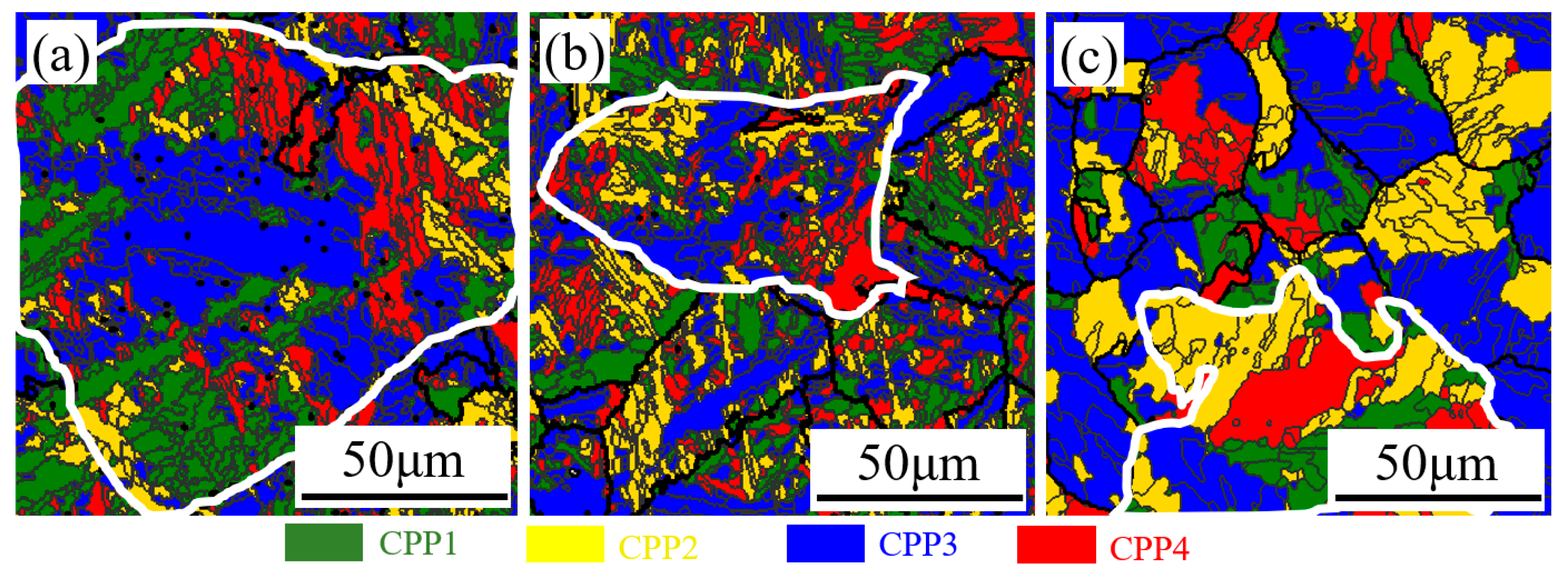
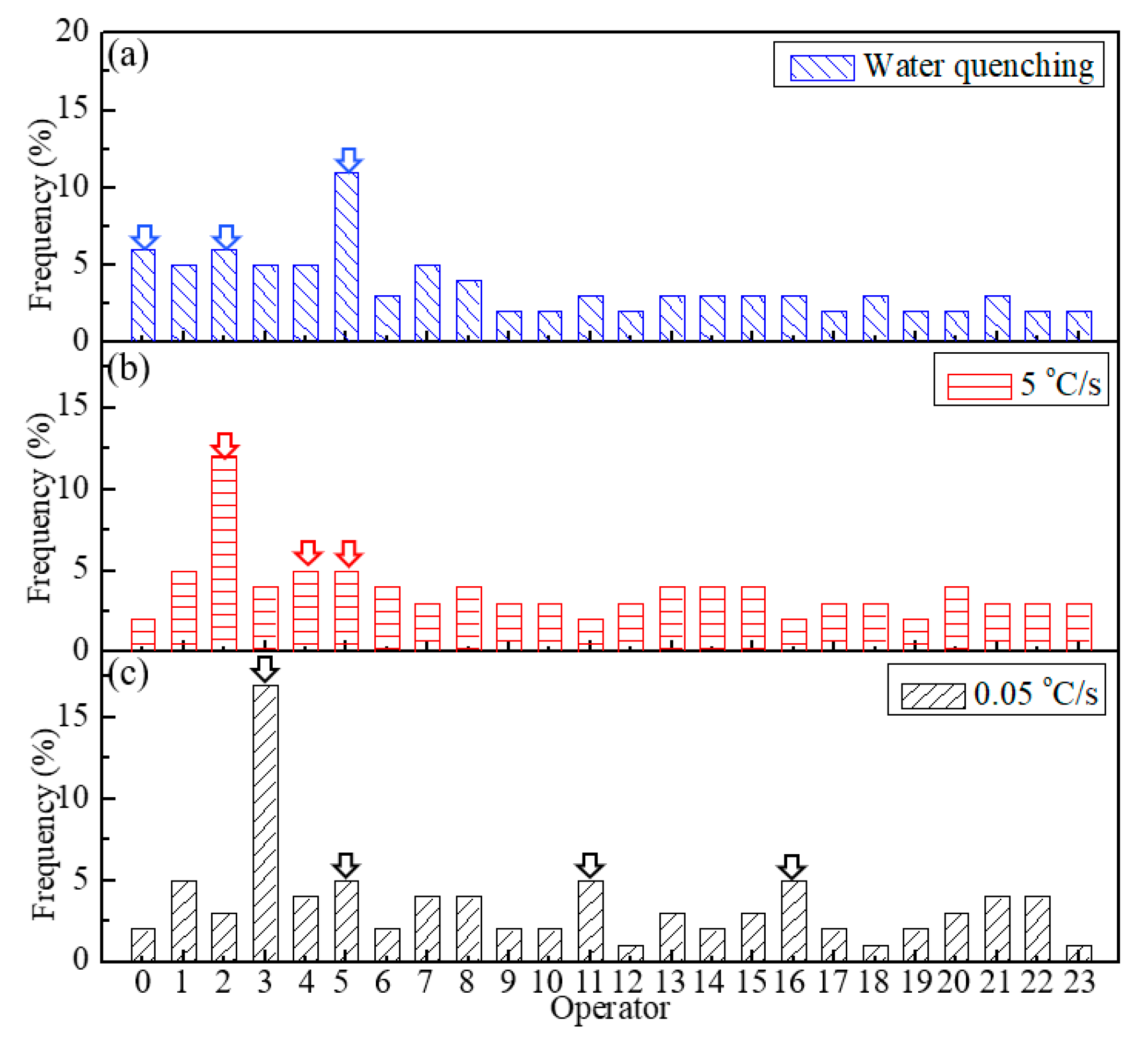
3.5. Operator Distribution Tendency

Figure 7 depicts the histograms of the distribution tendency of the operators at various cooling rates. As indicated by the blue hollow arrows in Figure 7a, high fractions of O0, O2, and O5 were detected in the as-quenched specimen, that is to say, more CPP packects were likely to exist in this specimen, as referred in Table 2. As indicates by the red hollow arrows in Figure 7b, O2, O4, and O5 were the most extensive in the specimen cooled at 5 °C/s. Nevertheless, compared with other operators in the specimen cooled at 0.05 °C/s, O3, O5, O11, and O16 were found more frequently (see black hollow arrows in Figure 7c). According to Table 2, these four operators were always inside the Bain packets. It was further demonstrated that more CPP packets with distinct geometric features were found in the specimens at higher cooling rates, e.g., assemblies of parallel laths. Meanwhile, non-geometric features, as shown in Figure 3c, were easily detected in Bain packets in the specimen at lower cooling rates.

4. Discussion

The morphological and crystallographic features of LM, LB, and GB were investigated in this study. Some researchers employed the phenomenological theory of martensite crystallography (PTMC) to demonstrate that the crystallographic characteristics of bainite are similar to those of martensite [18,19,20], including inter-variant strain [21], habit plane [22], surface relief [23]. However, it is not clear whether martensite and bainite possess the same boundary disorientation features, variant groupings, etc. Therefore, these issues will be discussed in the following section.

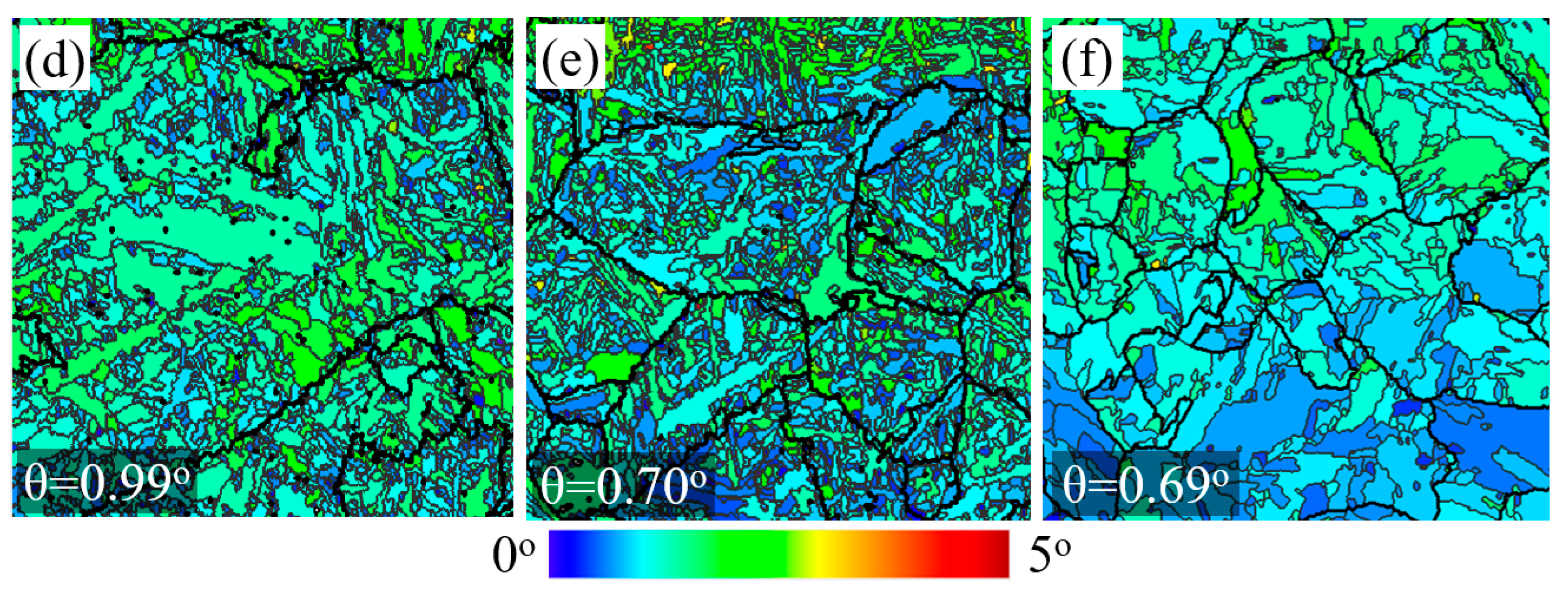
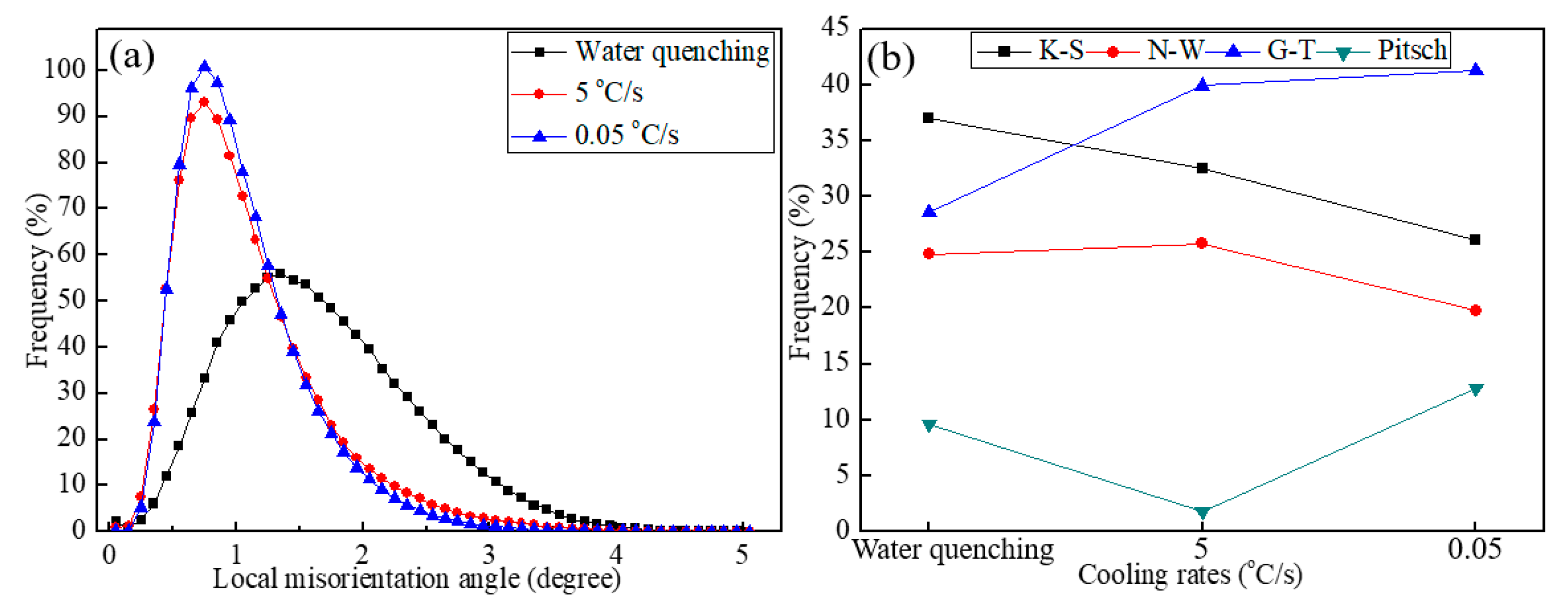
4.1. Determination of Strain Distribution and Dislocation Density

The calculated average misorientation angles in the samples subjected to water quenching, 5 °C/s, and 0.05 °C/s cooling rates were 0.99°/pixel, 0.70°/pixel, and 0.69°/pixel, respectively. Herein, 1 pixel was equal to 264.58 μm, therefore, the average misorientation angles were 0.0037°/μm, 0.0027°/μm, and 0.0.0026°/μm. As revealed in our previous research, the dislocation density depends linearly on the average misorientation angle [24]. Thus, it was demonstrated that high dislocation density exists in LM. It originates from the plastic accommodation of the transformation strain in martensite [25]. However, there was no huge variation of the dislocation density in a mixture of LM and LB compared with that in GB. Such similarities can be explained by a variant grouping in the succeeding transformations [26]. As mentioned above [11], variant groupings take place to accommodate the plastic strain of the transformation. If one accepts that martensite transformation is a shear transformation, the volume strain can be ignored because of its tiny effect compared with the shear strain for the distortion [27]. The edge areas of LB are always transformed later than the interior of LB, thus causing dislocations around the boundaries of LB [28]. Regarding the mixture of LB and LM, there was a time gap between the formation of variant groupings. During this gap, it can be inferred that the shear train caused by bainite transformation was partially released. Regarding GB, an unusual type of bainite due to the absence of cementite [16], boundary dislocations are not accumulated because of its ferritic matrix with diffusional transformation mode [29]. Finally, some results reported in previous studies were confirmed, e.g., lower dislocation density in bainite that transformed earlier than martensite [30].

4.2. Determination of Orientation Relationships

After comparing the experimental and simulated pole figures, we found that bainite and martensite in the samples exhibited K-S and G-T ORs. According to the continuous features in the pole figures in Figure 4, these ORs coexisted in each sample because the lattice invariant line was predominantly maintained by the transformed products [31]. A continuum of ORs between K-S, N-W, and Pitsch ORs can be ascribed to the very distortion generated by the transformation process rather than to the deformation of austenite. There exists a tendency toward a specific OR that depends on the composition of the alloy [32]. Our study shows that such differences also depend on the cooling rate. It is probable that this effect is a consequence of the change of the transformation temperature. This confirms Beladi’s idea that the phase transformation temperature has a significant effect on the OR between the parent phase and the daughter phase [6]. The OR of LM was mainly K-S OR, since the specimen in our study was composed of low-carbon high alloy. Nevertheless, LM in low-carbon and low-alloy steels approximately possesses a G-T relation with untransformed austenite [33]. G-T OR is between K-S and N-W, which are separated by around 5.26° [34]. G-T is often expressed as <110> γ about 2.5° from <111> α, (111)> γ, 1° from (011) α [35]. This OR was found to be at the highest frequency either in the mixture of LB and LM or in GB.

4.3. Determination of Boundary Features and Variant Groupings

Disorientation analyses have always been functional to investigate the frequency of variant grouping. In addition, 10 possible theoretical angles of disorientation between the variants have been reported, that is, 10.53°, 14.88°, 20.61°, 21.06°, 47.11°, 49.47°, 50.51°, 51.73°, 57.21°, and 60.00°, in accordance with K-S OR [36]. The corresponding angles linked to the disorientation peaks in Figure 6a are close to some of these angles, confirming the K-S relations in as-quenched martensite. As indicated by the solid arrows in Figure 6c, the theoretical peak with a disorientation of approximately 20° was absent in GB, indicating that some variants definitely vanished owing to variant groupings during transformation. Particularly, for GB derived by cooling at 0.05 °C/s, this is indicative that some variant pairs were absent. In the case of G-T OR, 16 possible theoretical disorientation angles were 5.35°, 9.4°, 13.3°, 16.5°, 18.2°, 18.9°, 50.0°, 50.8°, 51.8°, 51.9°, 52°, 55°, 56.5°, 56.9°, 59.1°, and 60.2° [6]. As indicated by the arrows in Figure 6b,c, not only the disorientation angles of 18° and 52° at 5 °C/s, but also the disorientation angles of 9° and 54.5° at 0.05 °C/s were more frequent than the other angles. These four angles are close to the theoretical disorientation angles of G-T OR, namely, 9.4°, 18.2°, 52°, and 55°. Thus, G-T OR is predominant in both lath bainite and granular bainite according to these related disorientation angles.
Generally, crystallography is influenced by the transformation temperature. The higher the transformation temperature, the coarser the microstructure, which provides more space for the generation of variants. This corresponds well with Takayama’s finding that Bain groupings are weakened, but CPP groupings are facilitated by reducing the transformation temperature in traditional martensitic and bainitic steels [14]. Therefore, variant groupings can be analyzed as follows.
On one hand, it is generally believed that the driving force is small at a high transformation temperature (i.e., slow cooling) [14], thus conducing high fraction of Bain grouping, e.g., the highest fraction of O3 in GB obtained with the cooling rate of 0.05 °C/s. Here, the driving force for transformation is regarded as the Gibbs free energy gap between parent and product phases with identical chemical compositions at the transformation temperature; On the other hand, fast cooling enhances the driving force for phase transformation, which results in more CPP and fewer Bain groupings for the nucleation of product phases along the austenite grain boundary [37]. Henceforth, plastic relaxation in austenite becomes more difficult at a lower temperature; thus, variant groupings would arise from the relaxation of internal stress caused by transformation misfit strain [38]. In other words, self-accommodation of the transformation strain is triggered by the formation of different variants in the neighbors, because the untransformed austenite matrix is strengthened at lower temperatures.

5. Conclusions

A detailed investigation on the distinction between lath martensite, lath bainite, and granular bainite was carried out from morphological and crystallographic viewpoints. The following results were obtained.
  • Both the martensite obtained by water quenching and the bainite obtained at 5 °C/s had lamellar morphologies. Granular bainite is a type of ferrite matrix, on which long stripes of martensite-austenite constituents are dispersed randomly along the grain boundaries or inside the grains.
  • The dislocation densities in lath bainite and granular bainite were lower than in lath martensite.
  • The K-S OR was the most frequent OR in as-quenched martensite, while G-T OR was predominant in both lath bainite and granular bainite
  • More CPP packets were generated at higher cooling rates (LM), while Bain packets were predominant at low cooling rates (LM and GB).

Author Contributions

Conceptualization, G.M. and C.C.; Methodology, G.M. and C.C.; Software, G.M., C.C. and X.M.; Validation, R.C. and J.C.; Formal Analysis, G.M.; Investigation, G.M., C.C., and R.L.; Resources, R.C.; Data Curation, G.M.; Writing-Original Draft Preparation, G.M.; Writing-Review & Editing, X.M. and R.L.; Visualization, G.M.; Supervision, C.C. and J.C.; Project Administration, R.C. and J.C.; Funding Acquisition, G.M. and R.C.

Funding

This research was funded by the National Natural Science Foundation of China (Nos. 51675255) and the Project of LUT Scholarship for Students’ Overseas Studies.

Acknowledgments

Many thanks to Yong Jiang and Xili Guo in Atlantic China Welding Consumables, Inc. for providing raw materials. G.J. Mao would like to thank all colleagues in LMTM (EPFL) for their help and care during his stay in Switzerland. G.J. Mao would like to thank all fellows in LUT for their help after he came back to China. G.J. Mao would like to thank his parents, sister, and brother for their love and their support to his work.

Conflicts of Interest

The authors declare no conflict of interest.

References

  1. Offerman, S.E.; van Dijk, N.H.; Sietsma, J.; Grigull, S.; Lauridsen, E.M.; Margulies, L.; Poulsen, H.F.; Rekveldt, M.T.; van der Zwaag, S. Grain nucleation and growth during phase transformations. Science 2002, 298, 1003–1005. [Google Scholar] [CrossRef] [PubMed]
  2. Morris, J. Stronger, tougher steels. Science 2008, 320, 1022–1023. [Google Scholar] [CrossRef] [PubMed]
  3. Wen, C.F.; Wang, Z.D.; Deng, X.T. Effect of heat input on the microstructure and mechanical properties of low alloy ultra-high strength structural steel welded joint. Steel Res. Int. 2018, 89, 1700500. [Google Scholar] [CrossRef]
  4. Mao, G.J.; Cao, R.; Cayron, C.; Logé, R.; Guo, X.L.; Jiang, Y.; Chen, J.H. Microstructural evolution and mechanical property development with nickel addition in low-carbon weld butt joints. J. Mater. Process. Technol. 2018, 262, 638–649. [Google Scholar] [CrossRef]
  5. Navarro-López, A.; Hidalgo, J.; Sietsma, J.; Santofimia, M.J. Characterization of bainitic/martensitic structures formed in isothermal treatments below the Ms temperature. Mater. Character. 2017, 128, 248–256. [Google Scholar] [CrossRef]
  6. Beladi, H.; Tari, V.; Timokhina, I.B.; Cizek, P.; Rohrer, G.S.; Rollett, A.D.; Hodgson, P.D. On the crystallographic characteristics of nanobainitic steel. Acta Mater. 2017, 127, 426–437. [Google Scholar] [CrossRef]
  7. Mao, G.J.; Cao, R.; Guo, X.L.; Jiang, Y.; Chen, J.H. In situ observation of kinetic processes of lath bainite nucleation and growth by laser scanning confocal microscope in reheated weld metals. Metall. Mater. Trans. A 2017, 48, 5783–5798. [Google Scholar] [CrossRef]
  8. Heung, N.H.; Suh, D.W. A model for transformation plasticity during bainite transformation of steel under external stress. Acta Mater. 2003, 51, 4907–4917. [Google Scholar]
  9. Cayron, C. One-step theory of fcc-bcc martensitic transformation. Acta Crystallogr. A 2013, 69, 498–509. [Google Scholar] [CrossRef]
  10. Inoue, T.; Matsuda, S.; Okamura, Y.; Aoki, K. The fracture of a low carbon tempered martensite. Trans. Jpn. Inst. Met. 1970, 11, 36–43. [Google Scholar] [CrossRef]
  11. Bouyne, E.; Flower, H.M.; Lindley, T.C.; Pineau, A. Use of EBSD technique to examine microstructure and cracking in a bainitic steel. Scr. Mater. 1998, 39, 295–300. [Google Scholar] [CrossRef]
  12. Morito, S.; Huang, X.; Furuhara, T.; Maki, T.; Hansen, N. The morphology and crystallography of lath martensite in alloy steels. Acta Mater. 2006, 54, 5323–5331. [Google Scholar] [CrossRef]
  13. Lambert-Perladea, A.; Gourgues, A.F.; Pineau, A. Austenite to bainite transformation in heat-affected zone of a high strength low alloy steel. Acta Mater. 2004, 52, 2337–2348. [Google Scholar] [CrossRef]
  14. Takayamaa, N.; Miyamoto, G.; Furuhara, T. Effects of transformation temperature on variant pairing of bainitic ferrite in low carbon steel. Acta Mater. 2012, 60, 2387–2396. [Google Scholar] [CrossRef]
  15. Cayron, C. ARPGE: A computer program to automatically reconstruct the parent grains from electron backscatter diffraction data. J. Appl. Crystallogr. 2007, 40, 1183–1188. [Google Scholar] [CrossRef] [PubMed]
  16. Josefsson, B.; Andren, H.O. Microstructure of granular bainite. J. Phy. Coll. 1988, 49, 293–298. [Google Scholar] [CrossRef]
  17. Hatherly, M.; Humphreys, F.J. Recrystallization and Related Annealing Phenomena, 2nd ed.; Elsevier: New York, NY, USA, 2004. [Google Scholar]
  18. Miyamoto, G.; Iwata, N.; Takayama, N.; Furuhara, T. Variant selection of lath martensite and bainite transformation in low carbon steel by ausforming. J. Alloy. Compd. 2013, 577, S528–S532. [Google Scholar] [CrossRef]
  19. Bowles, J.S.; MacKenzie, J.K. The crystallography of martensite transformations I. Acta Metall. 1954, 2, 129–137. [Google Scholar] [CrossRef]
  20. MacKenzie, J.K.; Bowles, J.S. The crystallography of martensite transformations II. Acta Metall. 1954, 2, 138–147. [Google Scholar] [CrossRef]
  21. Bowles, J.S.; Kennon, N.F. Crystallographic aspects of the bainite transformation. J. Aust. Inst. Met. 1960, 5, 106–113. [Google Scholar]
  22. Srinivasan, G.R.; Wayman, C.M. The crystallography of the bainite transformation I. Acta Metall. 1968, 16, 621–636. [Google Scholar] [CrossRef]
  23. Swallow, E.; Bhadeshia, H.K.D.H. High resolution observations of displacements caused by bainitic transformation. Mater. Sci. Technol. 1996, 12, 121–125. [Google Scholar] [CrossRef]
  24. Mao, G.J.; Cayron, C.; Cao, R.; Loge, R.; Chen, J.H. The relationship between low-temperature toughness and secondary crack in low-carbon bainitic weld metals. Mater. Character. 2018, 145, 516–526. [Google Scholar] [CrossRef]
  25. Maki, T.; Wayman, C.M. Substructure of ausformed martensite in Fe-Ni and Fe-Ni-C alloys. Metall. Trans. A 1976, 7, 1511–1518. [Google Scholar] [CrossRef]
  26. Bate, P.; Hutchinson, B. Effect of elastic interactions between displacive transformations on textures in steels. Acta Mater. 2000, 48, 3183–3192. [Google Scholar] [CrossRef]
  27. Bhadeshia, H.K.D.H. Bainite in Steels, 2nd ed.; Institute of Materials: London, UK, 2001. [Google Scholar]
  28. Kaneshita, T.; Miyamoto, G.; Furuhara, T. Variant selection in grain boundary nucleation of bainite in Fe-2Mn-C alloys. Acta Mater. 2017, 127, 368–378. [Google Scholar] [CrossRef]
  29. He, S.H.; He, B.B.; Zhu, K.Y.; Huang, M.X. Evolution of dislocation density in bainitic steel: Modeling and experiments. Acta Mater. 2018, 149, 46–56. [Google Scholar] [CrossRef]
  30. Cornide, J.; Miyamoto, G.; Caballero, F.G.; Furuhara, T.; Miller, M.K.; Garcia-Mateo, C. Distribution of dislocations in nanostructured bainite. Solid State Phenom. 2011, 172–714, 117–122. [Google Scholar] [CrossRef]
  31. Christian, J. Simple geometry and crystallography applied to ferrous bainites. Metall. Trans. A 1990, 21, 799–803. [Google Scholar] [CrossRef]
  32. Cayron, C. EBSD imaging of orientation relationships and variant groupings in different martensitic alloys and Widmanstatten iron meteorites. Mater. Character. 2014, 94, 93–110. [Google Scholar] [CrossRef]
  33. Kelly, P.M.; Jostsons, A.; Blake, R.G. The orientation relationship between lath martensite and austenite in low carbon, low alloy steels. Acta Metall. Mater. 1990, 38, 1075–1081. [Google Scholar] [CrossRef]
  34. Greninger, A.B.; Troiano, A.R. The mechanism of martensite formation. Met. Trans. 1949, 185, 590–598. [Google Scholar] [CrossRef]
  35. Zhang, M.X.; Kelly, P.M. Accurate orientation relationship between ferrite and austenite in low carbon martensite and granular bainite. Scr. Mater. 2002, 47, 749–755. [Google Scholar] [CrossRef]
  36. Morito, S.; Tanaka, H.; Konishi, R. The morphology and crystallography of lath martensite in Fe-C alloys. Acta Mater. 2003, 51, 1789–1799. [Google Scholar] [CrossRef]
  37. Furuhara, T.; Kawata, H.; Morito, S.; Maki, T. Crystallography of upper bainite in Fe–Ni–C alloys. Mater. Sci. Eng. A 2006, 431, 228–236. [Google Scholar] [CrossRef]
  38. Abbasi, M.; Nelson, T.W.; Sorensen, C.D. Analysis of variant selection in friction-stir-processed high-strength low-alloy steels. J. Appl. Crystallogr. 2013, 46, 716–725. [Google Scholar] [CrossRef]
Figure 1. Heat treatment cycles applied to the specimens.
Crystals 08 00468 g001
Figure 2. SEM graphs of three specimens at various cooling rates: (a) water-quenching; (b) 5 °C/s; (c) 0.05 °C/s.
Crystals 08 00468 g002
Figure 3. CPP packets in three specimens at various cooling rates: (a) water-quenching; (b) 5 °C/s; (c) 0.05 °C/s. The colors indicate four different CPP packets. Kernel average misorientation maps (one average value per grain): (d) water-quenching; (e) 5 °C/s; (f) 0.05 °C/s. θ is the local misorientation angle averaged on the grains of the map.
Crystals 08 00468 g003aCrystals 08 00468 g003b
Figure 4. Pole figures of martensitic and bainitic variants. First column: experimental results of {011}bcc pole figures. Simulated K-S, N-W, G-T, and Pitsch variants are listed in the second, third, fourth and fifth column, respectively. The {111}fcc planes are indicated by red points, while all possible variants are represented by black and blue spots.
Crystals 08 00468 g004
Figure 5. (a) Local misorientation distribution in three specimens; (b) function of the cooling rates for potential orientation relationships.
Crystals 08 00468 g005
Figure 6. Histogram of daughter grain disorientation in three specimens at various cooling rates: (a) water-quenching; (b) 5 °C/s; (c) 0.05 °C/s.
Crystals 08 00468 g006
Figure 7. Histogram of operator distribution in three specimens at various cooling rates: (a) water-quenching; (b) 5 °C/s; (c) 0.05 °C/s.
Crystals 08 00468 g007
Table 1. Ideal orientation relationships between γ structure (parent austenite) and α structure (daughter bainite/martensite) [6].
Orientation RelationshipParallelismMinimum Angle/Axis
Kurdjumov-Sachs (K-S){111}fcc//{110}bcc
<110>fcc//<111>bcc
42.85°/<0.968 0.178 0.178>
Nishiyama–Wassermann (N-W){111}fcc //{110}bcc
<112> fcc //<110> bcc
45.98°/<0.976 0.083 0.201>
Greninger-Troiano (G-T){110}fcc //{111}bcc
<123> fcc //<133> bcc
44.23°/<0.973 0.189 0.133>
Pitsch{100 fcc //{110}bcc
<110> fcc //<111> bcc
45.98°/<0.08 0.2 0.98>
Table 2. Operators’ details in various packets [9]; CPP: close-packed plane; CPD: close-packed direction.
NameOperators Inside the Packets
CPP packets{O0, O1, O2, O4, O5, O7}
CPD packets{O0, O2, O3, O8}
Bain packets{O0, O3, O5, O11, O16, O18, O20, O22}

