Article

Two-Stage Crystallizer Design for High Loading of Poorly Water-Soluble Pharmaceuticals in Porous Silica Matrices

1
Department of Chemical Engineering, Massachusetts Institute of Technology, Cambridge, MA 02139, USA
2
Pfizer Inc., Groton, CT 06340, USA
*
Author to whom correspondence should be addressed.
Crystals 2017, 7(5), 131; https://doi.org/10.3390/cryst7050131
Submission received: 30 March 2017 / Revised: 2 May 2017 / Accepted: 5 May 2017 / Published: 9 May 2017
(This article belongs to the Special Issue Effects of Confinement and Topography on Crystallization)

Abstract

:
While porous silica supports have been previously studied as carriers for nanocrystalline forms of poorly water-soluble active pharmaceutical ingredients (APIs), increasing the loading of API in these matrices is of great importance if these carriers are to be used in drug formulations. A dual-stage mixed-suspension, mixed-product removal (MSMPR) crystallizer was designed in which the poorly soluble API fenofibrate was loaded into the porous matrices of pore sizes 35 nm–300 nm in the first stage, and then fed to a second stage in which the crystals were further grown in the pores. This resulted in high loadings of over 50 wt % while still producing nanocrystals confined to the pores without the formation of bulk-sized crystals on the surface of the porous silica. The principle was extended to another highly insoluble API, griseofulvin, to improve its loading in porous silica in a benchtop procedure. This work demonstrates a multi-step crystallization principle API in porous silica matrices with loadings high enough to produce final dosage forms of these poorly water-soluble APIs.

1. Introduction

The low bioavailability of poorly water-soluble active pharmaceutical ingredients (APIs) is a challenge for API formulation and even selection in the drug discovery phase [1,2]. However, as nearly 90% of drugs in the discovery pipeline have low aqueous solubility [3], finding solutions to improve the physiochemical properties of these drugs is of high importance [4]. Forming nanocrystals of these APIs is a simple and promising solution to this problem [5]. Nanocrystalline APIs (<1000 nm) have improved surface area-to-volume ratios compared to bulk crystals, increasing dissolution rates [6,7], improving solubility [8,9,10], and enhancing permeability [11].
Numerous methodologies exist for producing pharmaceutical nanocrystals in both “top-down” approaches that control the nanosizing of larger crystals or “bottom-up” technologies which control the size of the crystal formed directly. These methods include milling [5], high-pressure homogenization [12], hydrosol methods [5,13], freeze-drying [14], supercritical fluid methods [14,15,16], and evaporative or antisolvent precipitation [17,18,19,20,21]. These methods have associated problems with contamination, high surfactant requirements, complex and energy-intensive procedures, difficulties controlling particle size distribution and polymorphism, and low production rates [22]. Many of these challenges are addressed with the confined crystallization approach, in which crystallization of the API is restricted to a micro- or nanoporous environment to form nanocrystals. Of particular interest and widely studied for drug delivery applications are rigid silica matrices including ordered mesoporous silica with and without surface modifications and grain size control [23,24,25,26,27,28,29], controlled pore glass [30,31,32,33,34], and fumed silica [35] due to the high degree of control over pore size and inert nature leading to nucleation control and polymorph stabilization [36,37,38,39].
While many studies have used porous silica matrices with extremely small pores (<10 nm) to confine high loadings of the amorphous forms of poorly water-soluble drugs to the effect of dramatically enhanced dissolution profiles [40,41,42,43,44], this study aimed to retain crystallinity of the drug loaded in porous matrices due to the long-term stability requirements for formulated pharmaceuticals [10,45]. In a previous study, a flow column-based loading process has been developed to first load the poorly water-soluble API ibuprofen into nanoporous silica and then crystallize the material in the pores through evaporation [46]. In this process, a maximum loading of about 33 wt % ibuprofen in the silica matrix was achieved. The researchers found that high API solution concentration and high solvent viscosity (within common solvents) were able to improve the loading achieved in the pores. Rinse volume was also a significant process parameter, which needed to be adjusted to be low enough to maintain drug loading, but high enough to remove bulk micron-sized crystals on the surface of the silica. This important work is a starting point for the development of continuous flow procedures for loading API into porous silica matrices.
Based on successful multi-stage continuous crystallizer designs in which the second stage and beyond aim to grow crystals which have nucleated in a first stage [47,48,49,50], a two-stage mixed-suspension, mixed-product removal (MSMPR) crystallizer was proposed to address the challenge of increasing the loading of API in porous silica. A single-stage MSMPR was employed for the continuous wetting of porous silica in a variety of pore sizes with a subsequent filtration step which accomplished the crystallization of fenofibrate (FEN) within the confined pores by either evaporation or cooling. This was then coupled to a second stage in which the drug-loaded silica was submerged in a slightly supersaturated FEN solution, allowing for growth of the nanocrystals within the pores.
Fenofibrate is a biopharmaceutics classification system (BCS) Class II drug (low solubility, high permeability) used for lowering cholesterol and was chosen for its low aqueous solubility of 0.8 μg/mL [51]. It has a molecular weight of 360.8 g/mol in a structure with an aromatic portion of the molecule containing two benzyl rings adjacent to an aliphatic region [52].
The principle was then applied to a bench-scale multiple-step impregnation procedure using an even less soluble compound, griseofulvin (GSF), to demonstrate improved loadings in this system. Samples were analyzed with thermogravimetric analysis (TGA) to determine loadings, differential scanning calorimetry (DSC) to study their nanocrystalline nature, and X-ray powder diffraction (XRPD) for form identification. This methodology was shown to improve drug loading of poorly water-soluble compounds, making drug-loaded biocompatible porous silica a viable dosage form.

2. Results

Poorly water-soluble compounds are of interest for confined crystallization work to produce small crystals with better dissolution ability. In previous studies, FEN nanocrystals confined to rigid porous silica matrices have been shown to have well-behaved thermal properties and enhanced dissolution rates [7,40]. A single polymorph has been shown to crystallize in pore sizes from 20 to 300 nm, which is ideal for studying melting point behavior in a simple system [30].

2.1. Selection of MSMPR Operating Parameters

Experiments were conducted on a Crystal 16 apparatus to determine the saturation solubility and metastable zone width (MSZW) of the FEN systems. The solubility was measured of FEN in ethyl acetate alone, and with porous silica also present in the vials. Figure 1 clearly shows the decrease in the metastable zone width with the addition of porous silica. The need to understand the working MSZW in a confined crystallization procedure is critical in the selection of a supersaturation level. The feed to stage two of the crystallizer was carefully selected to lie within the narrowed MSZW resulting from the presence of silica. This feed was designed to be supersaturated such that the feed could allow growth of the FEN crystals in the crystallizer while not dissolving the crystals already loaded in the pores. It also needed to be stable enough so as to not precipitate on its own. Indeed, some crystallizer runs were discarded due to issues with bulk crystal formation in the second stage. The saturation solubility of FEN in ethyl acetate at room temperature (25 °C) was found to be approximately 750 mg/mL. The supersaturation selected for the second-stage feed was about 1.4, a concentration of 1080 mg/mL. This value was selected to be well within the MSZW window.
The experiments were designed to maintain 10% w/v silica in the crystallizers. It is likely that the crystallizers could be run at much higher than 10% solids density with similar growth and loading. The low value of 10% was selected to be conservative in the “infinite solution” approximation for the second stage, wherein the mechanics of crystal growth and supersaturation were being carefully monitored.

2.2. Analysis of FEN Loading in MSMPR Experiments

Table 1 summarizes the loading results from the single- and two-stage MSMPR experiments held at 25 °C as determined by thermogravimetric analysis (TGA). The theoretical maximum loading from the first stage of the MSMPR was calculated assuming that all of the fenofibrate contained in the original 600 mg/mL (60% w/v) solution crystallized in the pores and that the pore volume of the silica was completely filled with solution. The theoretical “filled pore maximum” theoretical loading was also calculated based on the density of fenofibrate assuming that the entire pore volume was filled with crystal [53]. This basis is a maximum for comparison; however, complete filling of the tortuous porous network of the silica would be unlikely.
Only runs which did not show bulk crystallization in the vessels were selected for loading analysis. However, differential scanning calorimetry (DSC) scans did detect the presence of a small (<10 wt %) amount of surface crystals present on the silica powder in the 38 and 53 nm samples. This skews the loading data to suggest slightly higher possible loadings for these two pore sizes. In all pore sizes, the single-stage MSMPR experiments were able to achieve >75% of the theoretical maximum loading based on the amount of FEN solution expected to have wetted the pores. The loadings from the two-stage MSMPR were higher than their one-stage counterpart in all cases, indicating that the crystals confined to the pores in the first stage were then able to grow within the pores in the second stage. High weight percentage loadings were achieved in all cases. Most notably, due to its large pore volume, the porous silica Aeroperl® was able to be loaded with FEN to more than 50 wt % loading. While the samples with 38 and 53 nm pores did show some surface crystals, the relative contribution of surface to confined crystals indicated that there was still growth of the crystals confined to the pores in the two-stage MSMPR.
The single-stage MSMPR was also run at varying filter temperatures for a single pore size of 191 nm. Rather than allowing the crystallization to occur as a result of evaporation of the solvent and potentially losing more crystals in the wash step, cooling the solution in the crystal pores was hypothesized to allow for higher loadings even in the single-stage MSMPR. Table 2 summarizes the loadings determined by TGA and a description of the DSC scans for the varied temperature experiment.
For all temperatures but 15 °C, the DSC scans showed single peaks at a melting point depression, indicating that the crystals formed were confined to the pores of the silica matrix. There is a trend of higher loadings with cooler filter temperature. The samples crystallized at 15 °C were shown to have two peaks in the DSC scans corresponding to both confined crystals and crystals on the surface of the porous supports. Previous calculations based on the pore volume and density of FEN indicated that the theoretical filled pore maximum for FEN entirely occupying the pore volume for this pore size is 63.9 wt %. The loading values in Trials 1 and 3 at 15 °C further support the interpretation of DSC thermograms, indicating that both confined and surface crystals were present as the measured loading values exceed the theoretical maximum.

2.3. Dissolution Profile Enhancement

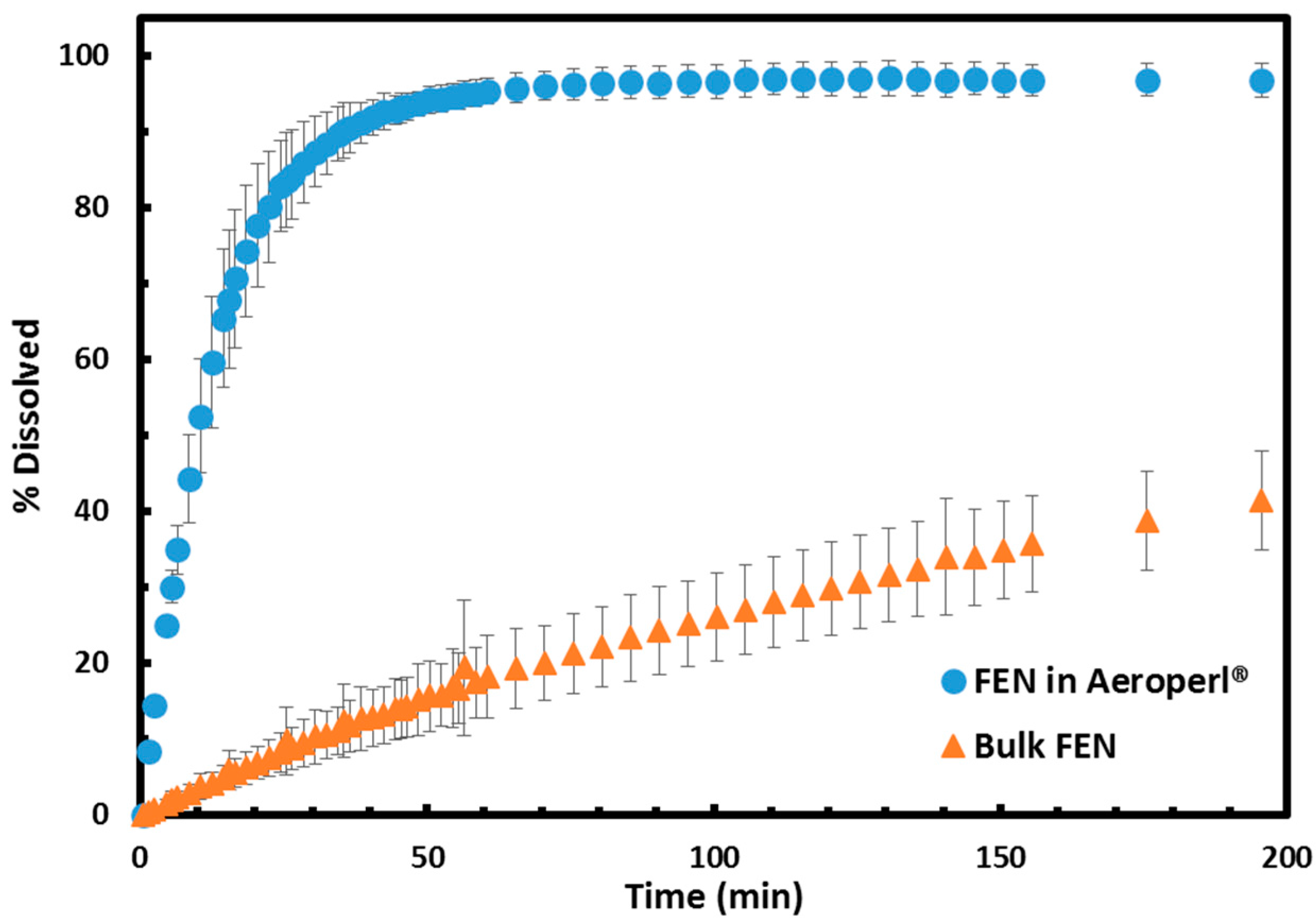
The FEN-loaded silica generated from the MSMPR crystallizers was studied in a dissolution apparatus to generate the dissolution profiles. Figure 2 shows the dissolution profile of FEN-loaded Aeroperl® from the two-stage MSMPR in contrast with bulk FEN crystals from the manufacturer. The Aeroperl® dissolution profiles are the most dramatically enhanced, due to a combination of the small crystal size (35 nm) and also likely diffusion effects from differences in the tortuosity and porosity between the different silicas used. The nanocrystalline FEN loaded in Aeroperl® was able to achieve more than 80% dissolution in 22.5 min, whereas the bulk FEN took 656 min for the same. The release time for FEN confined to Aeroperl® is the fastest seen of this API confined to any other form of porous silica [30].

2.4. Melting Point Depression Analysis of Nanocrystals with DSC

DSC scans were performed on each sample both to confirm that the crystals formed were confined to the pores and to study the effect of confinement on melting point depression. For the majority of the silica supports, the DSC scans showed a single, sharp peak at a melting point below the melting point of bulk FEN (81.6 °C ± 0.2 °C). This can be interpreted as indicating the presence of API crystals confined to the pores, without the presence of significant surface crystals of bulk size on the surface of the porous silica [30,46]. A few samples from pore sizes 38 and 53 nm showed two peaks on the DSC scans: a large peak at a temperature below 81.6 °C and a secondary peak at about 81.6 °C accounting for less than 10% of the total peak area. While this is interpreted as the presence of some crystals on the surface of the porous silica, the small relative quantity was accepted and these samples were still used for loading analysis.
A basic simplified Gibbs–Thomson analysis was employed to study the effect of confinement on melting point depression of the nanocrystals produced via the MSMPR methods [54]. Equation (1) relates the melting point depression to the nanocrystal size:
Δ T m = T m T m ( d ) = 4 γ s o l i d l i q u i d M T m d Δ H f u s ρ s o l i d
where T m is the bulk melting temperature, T m ( d ) is the melting temperature of a confined crystal with diameter d assumed equal to the pore diameter, M is the molecular mass, ρ s o l i d is the density of the solid, γ s o l i d l i q u i d is the surface free energy of the solid–liquid interface, and Δ H f u s is the molar enthalpy of fusion.
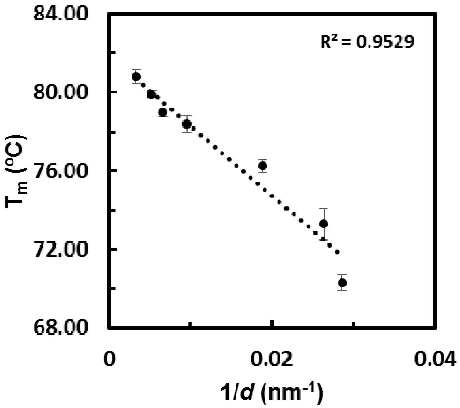
In previous studies, Equation (1) has been used to fit melting point data to show that the confined nanocrystals have the expected predictable linear-fit Gibbs–Thomson melting point depressions, indicating that a decrease in the surface interaction energy of the nanocrystals with the substrate, found in the numerator, is balanced by a simultaneous decrease in the enthalpy of fusion of the nanocrystals, found in the denominator. The melting point data from both the single-stage and two-stage MSMPR were plotted against the inverse of the pore diameter. Figure 3 shows that the confined crystals produced by MSMPRs have the expected melting point depression behavior with minimal deviation from the theory and minimal error in melting point temperature within a single pore size. The fit predicts a bulk melting point of 81.9 °C, very close to the measured bulk melting temperature of 81.6 °C.

2.5. Crystal Form Identification with X-ray Powder Diffraction (XRPD)

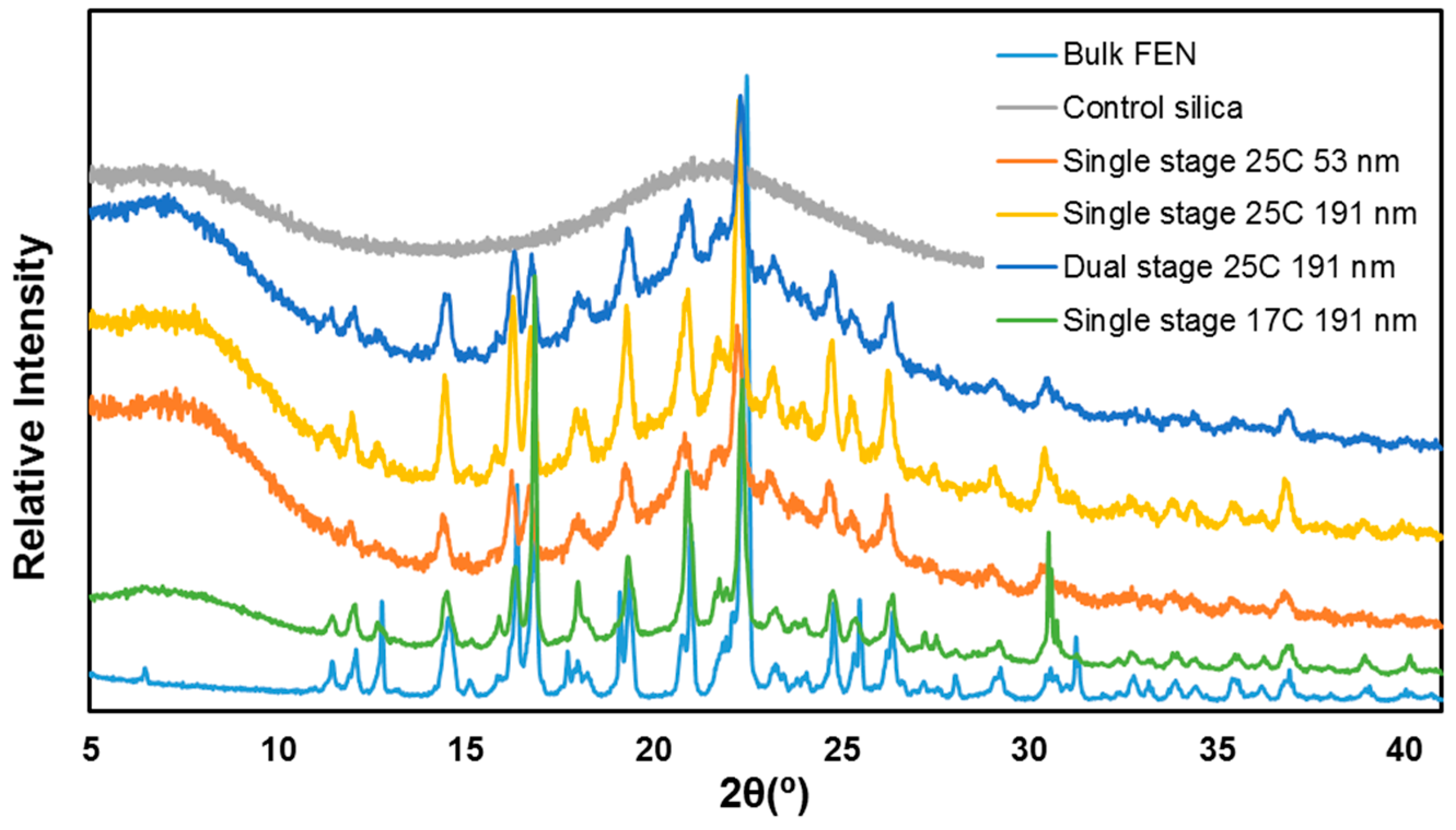
All samples showed the same XRPD peak pattern, both within trials of the same size porous silica and across different pore sizes. Furthermore, the crystal structure was the same regardless of the number of stages used in the MSMPR setup or the temperature of the filter. Figure 4 shows a representative scan of each type of experiment conducted (with the baseline silica amorphous feature present and scaled or shifted for clarity of comparison) showing identical peak patterns. Crystalline fenofibrate form I has reported theoretical diffractogram main peaks at 12° (2θ), 14.5° (2θ), 16.2° (2θ), 16.8° (2θ), and 22.4° (2θ) [52]. The identity of all samples of nanocrystalline fenofibrate as form I can be confirmed by matching peaks and the absence of other peak positions. The high loading of the single-stage MSMPR run with a cold (17 °C) filter for the loading step is evidenced in the relatively lower amorphous silica underlying baseline contribution to this scan.

2.6. Extension of Principle to Poorly Soluble Compounds

Griseofulvin (GSF) and indomethacin (IMC) were chosen as compounds that are not only poorly water-soluble but which also have low solubilities in most of the Food and Drug Administration (FDA) Class III solvents as challenging systems in which to achieve high pore loadings in a nanoporous silica matrix. Saturation solubility estimates exist for both APIs of about 40 mg/mL in acetone at 25 °C [55,56]. The theoretical maximum loading from the single-pass loading method was calculated assuming that all of the GSF or IMC contained in the original undersaturated solution of 30 mg/mL crystallized in the pore and that the pore volume of the silica was completely filled with solution. The theoretical “filled pore maximum” theoretical loading was also calculated assuming that the entirely pore volume was filled with crystals based on the density of GSF, 1.4 mg/mL [57], and assumed density of 1.0 mg/mL for a conservative estimate for IMC due to lack of available data. The experiments were all conducted in Aeroperl® of pore size 35 nm to have the highest pore volume silica (1.6 mL/g). A previous study [58] used IMC as a model compound to test similar loading procedures; however, this study used silica with smaller pore sizes and did not produce the crystalline form of drug which was targeted in this work.
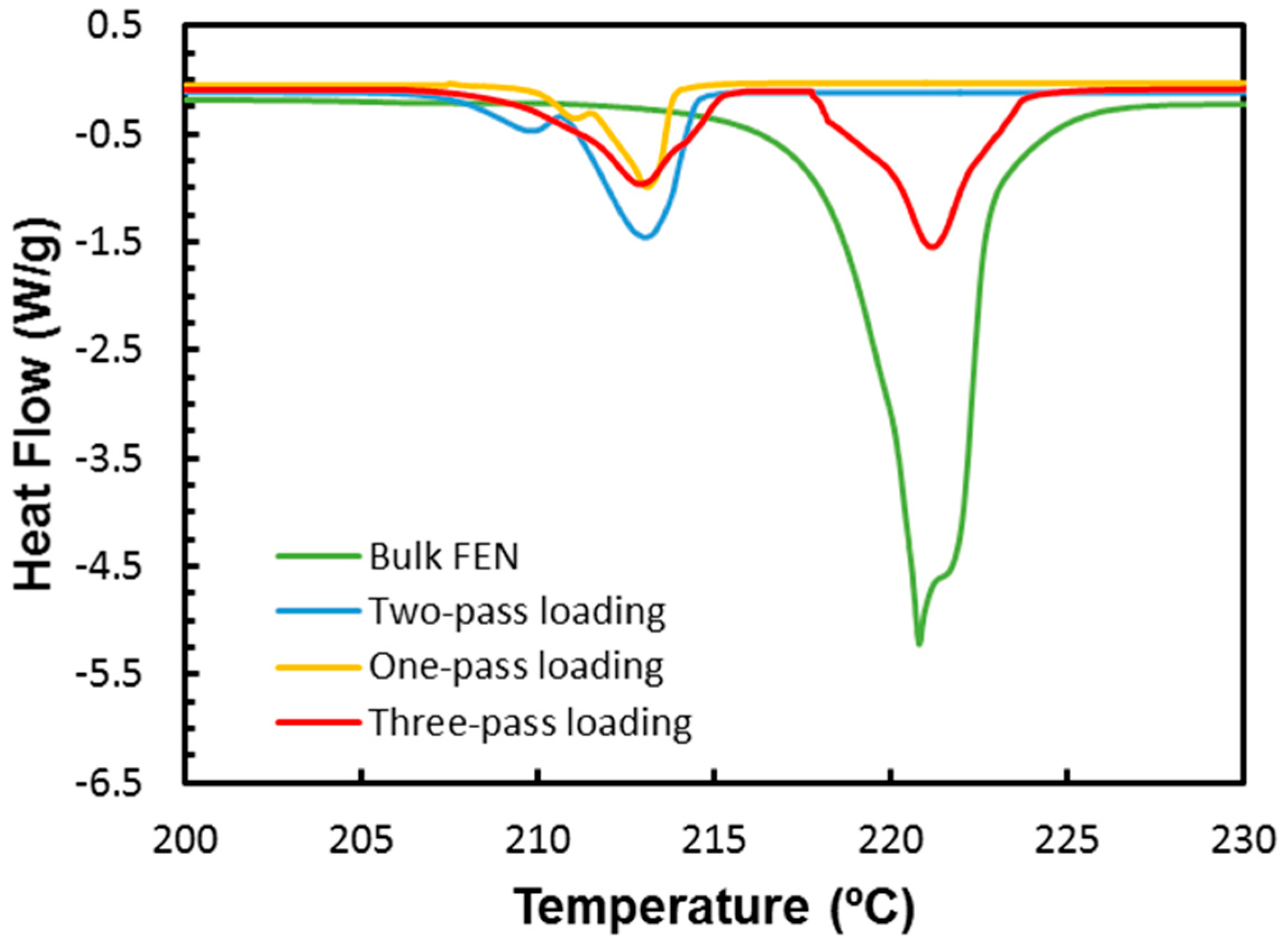
Table 3 summarizes the results of the experiments. Extremely low loadings were seen for the one-pass loading method, attributable to the very low concentration of API in solution. GSF was loaded to around 3.0 ± 0.6 wt % and the IMC was undetectable in these samples, likely indicating that what IMC had crystallized from the acetone solution was only on the surface of the porous silica and was washed off. In the two-pass loading system, the loading of GSF was increased to an appreciable value greater than 15 wt % and, in the three-pass system, the loading was above 25 wt %. The DSC thermograms of the loaded samples shown in Figure 5 show that in the two-pass system, all of the crystalline GSF produced was confined to the pores and showed the characteristic depressed melting point. However, in the three-pass system, significant surface crystals added to the higher loading as evidenced by the second peak at the bulk melting temperature. With the two- and three-pass methods, IMC was detectable in the samples but the DSC thermograms indicated that the majority of the contribution was from bulk crystals on the surface of the silica or amorphous content and the methodology was unable to produce IMC nanocrystals confined to the silica pores.

3. Discussion

Fenofibrate was successfully loaded into a range of nanoporous silica with varying pore sizes using a continuous MSMPR methodology. A single-stage MSMPR was shown to reliably wet the pores for subsequent crystallization by evaporation to yield average nanocrystalline FEN loadings across pore sizes of 37 wt % at 25 °C. Cooling crystallization was also employed on wetted porous silica from a single-stage MSMPR to achieve average FEN loadings of 48 wt %. When the single-stage design was coupled to a second-stage crystallizer in which a supersaturated solution was allowed to grow the nanocrystals which had already been loaded in the pores, loadings increased without substantial contributions from crystals on the surface of the porous silica. The average two-stage MSMPR loading across pore sizes was 51 wt % at 25 °C. The nanocrystalline FEN produced was the same polymorph across all studies and showed the expected melting point depression behavior expected from a Gibbs–Thomson relationship. A benchtop extension of the principle was shown to improve the loading of griseofulvin in porous silica from just 3.0 wt % to over 15 wt % with no surface crystals, but was unable to load the poorly water-soluble drug indomethacin with appreciable quantities in the pores; indomethacin showed a strong propensity for crystallization on the surface of the silica related to its nucleation and growth kinetics. Using a multi-stage MSMPR apparatus to load poorly soluble drugs in silica matrices has the ability to decouple nanocrystal formation from growth and allow for high drug loadings for these compounds. In particular, a material used in this study, Aeroperl® 300 Pharma, which not only has the highest pore volume but also meets the United States Pharmacopeia/National Formulary guidelines, is an attractive matrix for further pursuit for oral dosage forms.

4. Materials and Methods

4.1. Materials

Fenofibrate (FEN), griseofulvin (GSF) and indomethacin (IMC) were obtained from Xian Shunyi Bio-chemical Technology Company (Shaanxi, China). Silicon dioxide (silica) particles of varying pore sizes were obtained from three sources. Controlled pore glass (CPG) was obtained from Millipore (Billerica, MA, USA) in a pore size of 300 nm. More than 90% of the particle mass by weight fell within a 120/200 mesh size (75–125 μm). CPG was also obtained from Prime Synthesis (Aston, PA, USA) in pore sizes of 191.4, 151.5, 105.5, 53.7 and 38.3 nm. All had 100% particle mass with a grain size within a 120/200 mesh. Both the Millipore and Prime Synthesis materials were produced from borosilicate glass. At least 80% of the pores were within 10% of the mean pore diameter in pore size. Finally, Aeroperl® 300 Pharma, a fumed silica, was obtained from Evonik (Essen, Germany) with a pore size of about 35 nm. These particles had an average grain size of 30 μm. Solvents were purchased at ACS grade or higher purity from Fisher Scientific (Waltham, MA, USA).

4.2. Experimental Apparatus

4.2.1. Single-Stage MSMPR

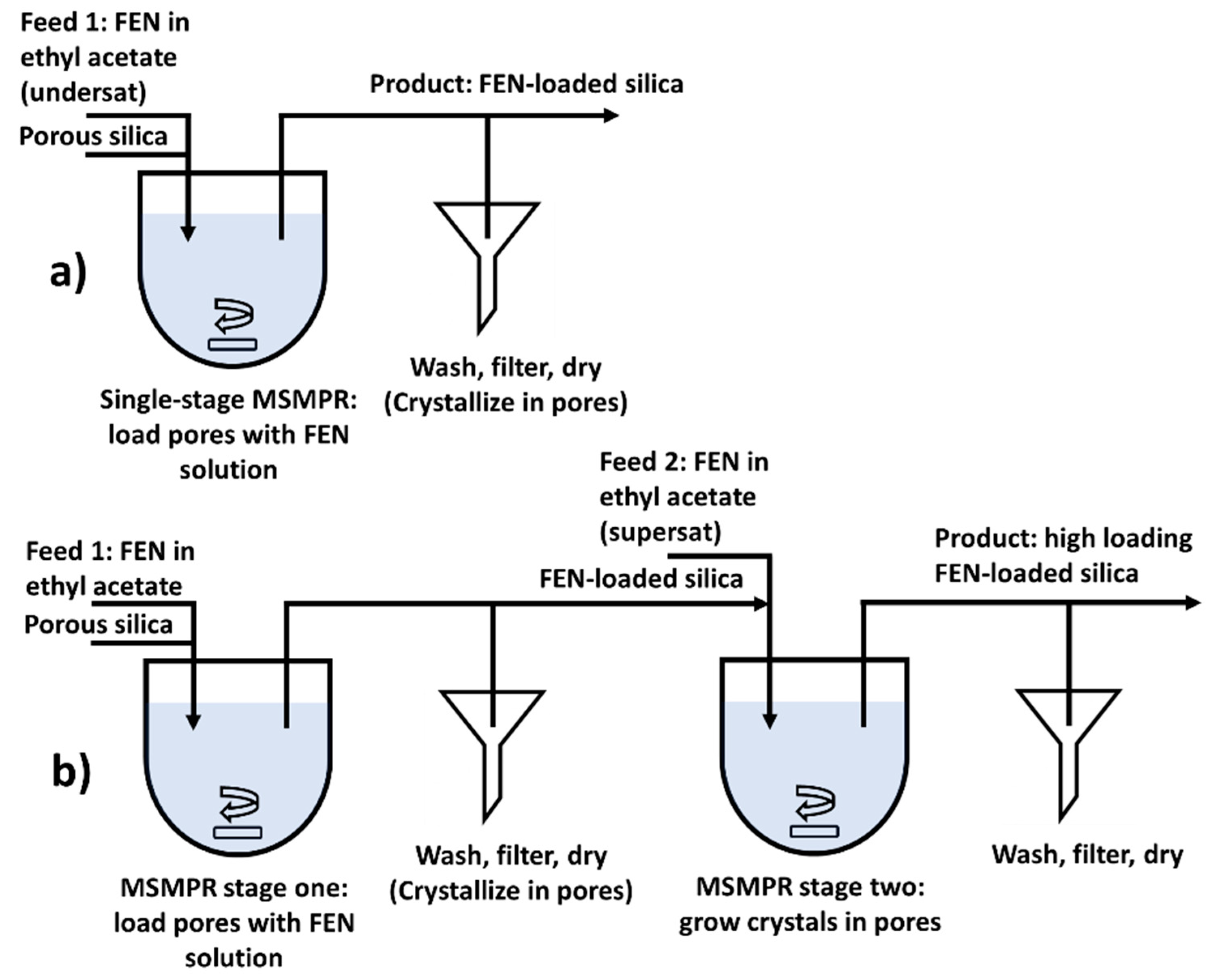
A single-stage MSMPR was used to crystallize fenofibrate in porous silica. A 50 mL round-bottomed water-jacketed reaction vessel with standard dimensions was used with magnetic stir bar and temperature separately controlled by an external water circulation controller (Thermo Scientific NESLAB RTE, Waltham, MA, USA). A solids content within the reactor of 10 mg porous silica/mL API solution was chosen; the empty reactor was primed with 500 mg silica to meet this value. The volume contribution of the silica content was deemed negligible. Peristaltic pumps (Masterflex P/S, Thermo Scientific) with Viton tubing (Cole-Parmer, Vernon Hills, IL, USA) were used for solution and slurry transfer. For the single-stage MSMPR, an undersaturated feed solution of 600 mg/mL fenofibrate in ethyl acetate was fed to the reactor at a flow rate of 1.7 mL/min to maintain a residence time of 30 min in the reactor. Slurry was removed intermittently so that every 3 min, 5 mL of slurry (10% of the vessel volume) was removed rapidly near the pump maximum flow rate of about 170 mL/min. After the liquid level again dropped below the outlet dip tube, the tube was pumped with air to clear remaining slurry. At this time, a replacement quantity of 50 mg of silica was added to the reactor volume to maintain the solids density at 10 mg/mL. The temperature of the feed and MSMPR were maintained at 25 °C. The pore size of the porous silica was varied to study the effect of confinement and subsequent crystal size on crystal properties and loading. Figure 6a shows a schematic of the apparatus.
The slurry removed containing API solution-loaded porous silica was fed to a water-jacketed glass frit filter connected to an external water circulation temperature control (Thermo Scientific NESLAB RTE) with qualitative Whatman Grade 1 filter paper (GE Healthcare, Chicago, IL, USA). The filter was maintained at 25 °C. The first ten volumes of recovered slurry were discarded to allow the system a full residence time turnover. The system was then run for 90 min to capture three full residence times. This resulted in the capture of 150 mL of slurry containing a total of about 1500 mg porous silica. The final filter cake was dried in air and washed with 5 mL cold (chilled on ice 0–5 °C) ethanol to wash off residual solvent or surface API crystals from the outside of the porous silica beads. In a second study, the temperature of the filter was varied below 25 °C at a fixed pore volume to induce crystallization while minimizing solvent evaporation. The powder was then dried in the filter by flowing air. All experiments were carried out in triplicate.

4.2.2. Two-Stage MSMPR

For the two-stage MSMPR, two 50 mL water-jacketed reaction vessels were used. The same peristaltic pumps, tubing, and external water temperature circulators were employed. The first stage was essentially a replica of the single-stage experiment, with a 600 mg/mL fenofibrate in ethyl acetate feed with continuously supplied porous silica. The reactor vessel and filter were held at 25 °C with intermittent slurry withdrawals every 3 min of 10% of the volume of the reactor and unloaded porous silica replaced to the vessel at this time. Due to the inability to continuously harvest the filter cake of API-loaded porous silica from the first stage for supply to the second stage, the second stage was time-decoupled from the first to allow for the buildup of enough filtered, loaded material from stage one to accumulate to be fed to stage two.
The feed to the second stage was a supersaturated solution of fenofibrate in ethyl acetate at 1080 mg/mL and 1.7 mL/min. The second reactor vessel was primed with 500 mg of stage one API-loaded silica. The same residence time of 30 min was maintained and the reactor was held at 25 °C. The same intermittent withdrawal scheme of 5 mL every 3 min was employed. The silica added to the reactor in 50 mg intervals every 3 min was API-loaded silica from stage one. The slurry was sent to a water-jacketed glass frit filter with qualitative Grade 1 filter paper (Whatman) maintained at 25 °C with an external water circulation controller (Thermo Scientific NESLAB RTE). The samples were washed at each withdrawal with 1 mL cold (chilled on ice 0–5 °C) ethanol to wash off residual solution and surface crystals. Figure 6b shows a schematic of the setup. The samples were then dried in the filter by flowing air. Again, the first ten slurry volumes were discarded. The crystallizer was run for two complete residence times to utilize all of the recovered loaded silica from stage one, resulting in approximately 1000 mg of captured material at the end of stage two. Experiments were carried out in triplicate.

4.2.3. Extension of Principle to Poorly Water-Soluble Compounds

Griseofulvin and indomethacin were selected for a bench scale extension of the multiple-stage MSMPR principle of a first stage to load the pore with an initial crystalline material and a second stage to grow the crystals in pores. Single-, double- and triple-pass loading methods were employed for each system. In the single loading method, a previously established technique [46] was employed of submerging the particles in a large volume (>250 mL) of undersaturated API solution using a fine mesh basket. About 1 gram of porous silica particles was immersed in a solution of 30 mg/mL GSF in acetone using a fine mesh basket uncontrolled at room temperature. The solution was left to wet and enter the silica pores for 20 min before removing and wicking away excess solution using a paper towel. After the silica particles were removed from the solution, the particles were rinsed with 2.5 mL of cold ethanol (chilled on ice 0–5 °C). The rinse was wicked away using a paper towel and the porous silica was removed to dry at room temperature for approximately 15 h.
In the double-pass loading method, prepared loaded samples from a single-pass experiment were then submerged using the fine mesh basket in a large volume very slightly supersaturated solution of 45 mg/mL GSF in acetone. The samples were held for five days at 25 °C in a recirculated water bath (Thermo Scientific NESLAB RTE) at 25 °C. The samples were then removed, solution wicked away, and rinsed with cold ethanol as above before being separated from any visible bulk crystals and dried at room temperature for about 15 h. Finally, for the triple-pass loaded systems, a third submersion step in a slightly more supersaturated GSF solution of 50 mg/mL was completed for another five days, with subsequent identical wash and dry procedures. The experiments were repeated using IMC solutions in acetone at the same concentrations for the one-pass, two-pass, and three-pass loading methods. All experiments were carried out in triplicate.

4.3. Analytical Techniques

4.3.1. X-ray Powder Diffraction

XRPD was performed on all samples using a PANalytical X’Pert PRO (Almelo, The Netherlands) diffractometer at 45 kV with an anode current of 40 mA. The instrument has a PW3050/60 standard resolution goniometer and a PW3373/10 Cu LFF DK241245 X-ray tube. Samples were placed on a spinner stage in reflection mode. Settings on the incident beam path included: soller slit 0.04 rad, mask fixed 10 mm, programmable divergence slit and fixed 1° anti-scatter slit. Settings on the diffracted beam path include: soller slit 0.04 rad and programmable anti-scatter slit. The scan was set as a continuous scan: 2θ angle between 4° and 40°, step size .0167113° and a time per step of 31.115 s.

4.3.2. Thermogravimetric Analysis

TGA was performed on a Q500 instrument from TA instruments (Newcastle, DE, USA) connected with a nitrogen gas cylinder to maintain a flow rate of 25 mL/min to maintain an inert gas environment in the sample chamber. Between 5 and 10 mg of sample were loaded on platinum sample pans from TA Instruments. The samples were allowed to equilibrate at 30 °C and then heated at 10 °C/min to 300 °C.

4.3.3. Differential Scanning Calorimetry

A Q2000 instrument from TA instruments was used for the DSC analysis. Inert atmosphere environment was maintained in the sample chamber using a nitrogen gas cylinder set to a flow rate of 50 mL/min. An extra refrigerated cooling system (RCS 40, TA Instruments) was used to widen the available temperature range to between −40 and 400 °C. Tzero® pans and lids were used with ~5 mg of sample. A heating rate of 10 °C/min was applied and the samples were scanned from −20 to 250 °C. When determining the enthalpy of fusion for a given sample, the DSC curve was integrated for 30 °C centered on the melting temperature of each pore size to capture the entire melting event. An exception to this rule was made in samples with a secondary peak present from surface crystals in which case the integration limit was set to exclude the secondary melting event.

4.3.4. Solubility Measurements

The saturation solubility for FEN was measured in ethyl acetate at different concentrations by adding a known amount of FEN and 1 mL of solvent, respectively, to a 1.5 mL glass vial. The vials were then placed in a Crystal16 (Avantium, Amsterdam, the Netherlands), and the heating and cooling rates were set to 0.3 °C/min. The samples were stirred with a controlled stirring speed of 700 rpm using magnetic stirring bars. The samples were heated with a heating rate of 0.3 °C/min from 5 to 50 °C. The temperature at which the suspension turned into a clear solution was recorded and assumed to be the saturation temperature. The clear points generated the solubility curve. After a waiting time of 30 min at 50 °C, the clear solution was cooled to 5 °C with a cooling rate of 0.3 °C/min to recrystallize the FEN. The cloud point curve was generated as the metastable zone limit (see Section 3 for discussion).

4.3.5. Dissolution Testing

A dissolution test meeting the USP standard for fenofibrate was performed using a USP Dissolution Apparatus 2 at 37 °C. Built-in ultraviolet-visible spectroscopy was used to determine percentage of dissolved FEN at 286 nm. The dissolution buffer used was 0.025 M sodium dodecyl sulfate solution (Sigma Aldrich (St. Louis, MO, USA). The dissolution apparatus operated at 75 rpm using 900 mL buffer solution, which was allowed to equilibrate at temperature before the addition of drug-loaded silica. Enough sample of FEN-loaded silica was added such that the targeted concentration of fenofibrate in solution was 15 μg/mL, within the expected linear range. Samples were acquired for about 29 h.

Acknowledgments

We would like to thank the Novartis-MIT Center for Continuous Manufacturing for financial support and instrumentation use. Leia Dwyer is grateful to Carlos Pons Siepermann, Jennifer Moffitt Schall, and Marcus O’Mahony for valuable assistance and discussions.

Author Contributions

Leia Dwyer, Samir Kulkarni, and Allan Myerson conceived and designed the experiments; Leia Dwyer and Samir Kulkarni performed the experiments and analyzed the data; Luzdary Ruelas performed the benchtop experiments with griseofulvin and indomethacin; Leia Dwyer wrote the paper.

Conflicts of Interest

The authors declare no conflict of interest. The founding sponsors had no role in the design of the study; in the collection, analyses, or interpretation of data; in the writing of the manuscript, and in the decision to publish the results.

References

  1. Stegemann, S.; Leveiller, F.; Franchi, D.; de Jong, H.; Lindén, H. When poor solubility becomes an issue: From early stage to proof of concept. Eur. J. Pharm. Sci. Off. J. Eur. Fed. Pharm. Sci. 2007, 31, 249–261. [Google Scholar] [CrossRef] [PubMed]
  2. Lipinski, C.A. Drug-like properties and the causes of poor solubility and poor permeability. J. Pharmacol. Toxicol. Methods 2000, 44, 235–249. [Google Scholar] [CrossRef]
  3. Kalepu, S.; Nekkanti, V. Insoluble drug delivery strategies: Review of recent advances and business prospects. Acta Pharm. Sin. B 2015, 5, 442–453. [Google Scholar] [CrossRef] [PubMed]
  4. Otto, D.P.; de Villiers, M.M. Physicochemical Principles of Nanosized Drug Delivery Systems. In Nanotechnology in Drug Delivery; de Villiers, M.M., Aramwit, P., Kwon, G.S., Eds.; Biotechnology: Pharmaceutical Aspects; Springer: New York, NY, USA, 2009; pp. 3–33. [Google Scholar]
  5. Shegokar, R.; Müller, R.H. Nanocrystals: Industrially feasible multifunctional formulation technology for poorly soluble actives. Int. J. Pharm. 2010, 399, 129–139. [Google Scholar] [CrossRef] [PubMed]
  6. Müller, R.H.; Peters, K. Nanosuspensions for the formulation of poorly soluble drugs: I. Preparation by a size-reduction technique. Int. J. Pharm. 1998, 160, 229–237. [Google Scholar] [CrossRef]
  7. Zuo, B.; Sun, Y.; Li, H.; Liu, X.; Zhai, Y.; Sun, J.; He, Z. Preparation and in vitro/in vivo evaluation of fenofibrate nanocrystals. Int. J. Pharm. 2013, 455, 267–275. [Google Scholar] [CrossRef] [PubMed]
  8. Mullin, J.W. 3—Solutions and solubility. In Crystallization, 4th ed.; Butterworth-Heinemann: Oxford, UK, 2001; pp. 86–134. [Google Scholar]
  9. Kim, K.; Lee, I.S.; Centrone, A.; Hatton, T.A.; Myerson, A.S. Formation of Nanosized Organic Molecular Crystals on Engineered Surfaces. J. Am. Chem. Soc. 2009, 131, 18212–18213. [Google Scholar] [CrossRef] [PubMed]
  10. Junghanns, J.-U.A.H.; Müller, R.H. Nanocrystal technology, drug delivery and clinical applications. Int. J. Nanomed. 2008, 3, 295–310. [Google Scholar]
  11. Hu, J.; Johnston, K.P.; Williams, R.O., 3rd. Nanoparticle Engineering Processes for Enhancing the Dissolution Rates of Poorly Water Soluble Drugs. Drug Dev. Ind. Pharm. 2004, 30, 233–245. [Google Scholar] [CrossRef] [PubMed]
  12. Keck, C.M.; Müller, R.H. Drug nanocrystals of poorly soluble drugs produced by high pressure homogenisation. Eur. J. Pharm. Biopharm. 2006, 62, 3–16. [Google Scholar] [CrossRef] [PubMed]
  13. List, M.; Sucker, H. Hydrosols of Pharmacologically Active Agents and Their Pharmaceutical Compositions Comprising Them. U.S. Patent 5,389,382 A, 14 February 1995. [Google Scholar]
  14. De Waard, H.; Grasmeijer, N.; Hinrichs, W.L.J.; De Beer, T.; Frijlink, H.W. A Process Suitable for Large-Scale Production of Drug Nanocrystals. Pharm. Technol. 2011, 35, 58–62. [Google Scholar]
  15. Lee, S.; Nam, K.; Kim, M.S.; Jun, S.W.; Park, J.-S.; Woo, J.S.; Hwang, S.-J. Preparation and characterization of solid dispersions of itraconazole by using aerosol solvent extraction system for improvement in drug solubility and bioavailability. Arch. Pharm. Res. 2005, 28, 866–874. [Google Scholar] [CrossRef] [PubMed]
  16. Rogers, T.L.; Johnston, K.P.; Williams, R.O., 3rd. Solution-Based Particle Formation of Pharmaceutical Powders by Supercritical or Compressed Fluid Co2 and Cryogenic Spray-Freezing Technologies. Drug Dev. Ind. Pharm. 2001, 27, 1003–1015. [Google Scholar] [CrossRef] [PubMed]
  17. Sarkari, M.; Brown, J.; Chen, X.; Swinnea, S.; Williams, R.O., III; Johnston, K.P. Enhanced drug dissolution using evaporative precipitation into aqueous solution. Int. J. Pharm. 2002, 243, 17–31. [Google Scholar] [CrossRef]
  18. Chen, X.; Young, T.J.; Sarkari, M.; Williams, R.O., III; Johnston, K.P. Preparation of cyclosporine A nanoparticles by evaporative precipitation into aqueous solution. Int. J. Pharm. 2002, 242, 3–14. [Google Scholar] [CrossRef]
  19. Panagiotou, T.; Mesite, S.V.; Fisher, R.J. Production of Norfloxacin Nanosuspensions Using Microfluidics Reaction Technology through Solvent/Antisolvent Crystallization. Ind. Eng. Chem. Res. 2009, 48, 1761–1771. [Google Scholar] [CrossRef]
  20. Chan, H.-K.; Kwok, P.C.L. Production methods for nanodrug particles using the bottom-up approach. Adv. Drug Deliv. Rev. 2011, 63, 406–416. [Google Scholar] [CrossRef] [PubMed]
  21. Khan, S.; de Matas, M.; Zhang, J.; Anwar, J. Nanocrystal Preparation: Low-Energy Precipitation Method Revisited. Cryst. Growth Des. 2013, 13, 2766–2777. [Google Scholar] [CrossRef]
  22. Möschwitzer, J.P. Drug nanocrystals in the commercial pharmaceutical development process. Int. J. Pharm. 2013, 453, 142–156. [Google Scholar] [CrossRef] [PubMed]
  23. Thomas, M.J.K.; Slipper, I.; Walunj, A.; Jain, A.; Favretto, M.E.; Kallinteri, P.; Douroumis, D. Inclusion of poorly soluble drugs in highly ordered mesoporous silica nanoparticles. Int. J. Pharm. 2010, 387, 272–277. [Google Scholar] [CrossRef] [PubMed]
  24. Qian, K.K.; Bogner, R.H. Application of Mesoporous Silicon Dioxide and Silicate in Oral Amorphous Drug Delivery Systems. J. Pharm. Sci. 2012, 101, 444–463. [Google Scholar] [CrossRef] [PubMed]
  25. Wang, S. Ordered mesoporous materials for drug delivery. Microporous Mesoporous Mater. 2009, 117, 1–9. [Google Scholar] [CrossRef]
  26. Azaïs, T.; Tourné-Péteilh, C.; Aussenac, F.; Baccile, N.; Coelho, C.; Devoisselle, J.-M.; Babonneau, F. Solid-State NMR Study of Ibuprofen Confined in MCM-41 Material. Chem. Mater. 2006, 18, 6382–6390. [Google Scholar] [CrossRef]
  27. Azad, M.; Moreno, J.; Bilgili, E.; Davé, R. Fast dissolution of poorly water soluble drugs from fluidized bed coated nanocomposites: Impact of carrier size. Int. J. Pharm. 2016, 513, 319–331. [Google Scholar] [CrossRef] [PubMed]
  28. Geszke-Moritz, M.; Moritz, M. APTES-modified mesoporous silicas as the carriers for poorly water-soluble drug. Modeling of diflunisal adsorption and release. Appl. Surf. Sci. 2016, 368, 348–359. [Google Scholar] [CrossRef]
  29. Martín, A.; García, R.A.; Karaman, D.S.; Rosenholm, J.M. Polyethyleneimine-functionalized large pore ordered silica materials for poorly water-soluble drug delivery. J. Mater. Sci. 2014, 49, 1437–1447. [Google Scholar] [CrossRef]
  30. Dwyer, L.; Michaelis, V.; O’Mahony, M.; Griffin, R.; Myerson, A. Confined crystallization of fenofibrate in nanoporous silica. CrystEngComm 2015, 17, 7922–7929. [Google Scholar] [CrossRef] [PubMed]
  31. Jackson, C.L.; McKenna, G.B. Vitrification and Crystallization of Organic Liquids Confined to Nanoscale Pores. Chem. Mater. 1996, 8, 2128–2137. [Google Scholar] [CrossRef]
  32. Ha, J.-M.; Hamilton, B.D.; Hillmyer, M.A.; Ward, M.D. Phase Behavior and Polymorphism of Organic Crystals Confined within Nanoscale Chambers. Cryst. Growth Des. 2009, 9, 4766–4777. [Google Scholar] [CrossRef]
  33. Ha, J.-M.; Wolf, J.H.; Hillmyer, M.A.; Ward, M.D. Polymorph Selectivity under Nanoscopic Confinement. J. Am. Chem. Soc. 2004, 126, 3382–3383. [Google Scholar] [CrossRef] [PubMed]
  34. Sonnenberger, N.; Anders, N.; Golitsyn, Y.; Steinhart, M.; Enke, D.; Saalwächter, K.; Beiner, M. Pharmaceutical nanocrystals confined in porous host systems—Interfacial effects and amorphous interphases. Chem. Commun. 2016, 52, 4466–4469. [Google Scholar] [CrossRef] [PubMed]
  35. Yang, X.; Ong, T.C.; Michaelis, V.K.; Heng, S.; Huang, J.; Griffin, R.G.; Myerson, A.S. Formation of organic molecular nanocrystals under rigid confinement with analysis by solid state NMR. CrystEngComm 2014, 16, 9345–9352. [Google Scholar] [CrossRef] [PubMed]
  36. Jiang, Q.; Ward, M.D. Crystallization under nanoscale confinement. Chem. Soc. Rev. 2014, 43, 2066–2079. [Google Scholar] [CrossRef] [PubMed]
  37. Rengarajan, G.T.; Enke, D.; Steinhart, M.; Beiner, M. Size-dependent growth of polymorphs in nanopores and Ostwald’s step rule of stages. Phys. Chem. Chem. Phys. 2011, 13, 21367–21374. [Google Scholar] [CrossRef] [PubMed]
  38. Graubner, G.; Rengarajan, G.T.; Anders, N.; Sonnenberger, N.; Enke, D.; Beiner, M.; Steinhart, M. Morphology of Porous Hosts Directs Preferred Polymorph Formation and Influences Kinetics of Solid/Solid Transitions of Confined Pharmaceuticals. Cryst. Growth Des. 2014, 14, 78–86. [Google Scholar] [CrossRef]
  39. Beiner, M.; Rengarajan; Pankaj, S.; Enke, D.; Steinhart, M. Manipulating the Crystalline State of Pharmaceuticals by Nanoconfinement. Nano Lett. 2007, 7, 1381–1385. [Google Scholar] [CrossRef] [PubMed]
  40. Ahern, R.J.; Hanrahan, J.P.; Tobin, J.M.; Ryan, K.B.; Crean, A.M. Comparison of fenofibrate-mesoporous silica drug-loading processes for enhanced drug delivery. Eur. J. Pharm. Sci. 2013, 50, 400–409. [Google Scholar] [CrossRef] [PubMed]
  41. Mehanna, M.M.; Motawaa, A.M.; Samaha, M.W. Tadalafil inclusion in microporous silica as effective dissolution enhancer: Optimization of loading procedure and molecular state characterization. J. Pharm. Sci. 2011, 100, 1805–1818. [Google Scholar] [CrossRef] [PubMed]
  42. Van Speybroeck, M.; Barillaro, V.; Thi, T.D.; Mellaerts, R.; Martens, J.; Van Humbeeck, J.; Vermant, J.; Annaert, P.; Van den Mooter, G.; Augustijns, P. Ordered mesoporous silica material SBA-15: A broad-spectrum formulation platform for poorly soluble drugs. J. Pharm. Sci. 2009, 98, 2648–2658. [Google Scholar] [CrossRef] [PubMed]
  43. Hillerström, A.; van Stam, J.; Andersson, M. Ibuprofen loading into mesostructured silica using liquid carbon dioxide as a solvent. Green Chem. 2009, 11, 662–667. [Google Scholar] [CrossRef]
  44. Zhang, Y.; Zhi, Z.; Jiang, T.; Zhang, J.; Wang, Z.; Wang, S. Spherical mesoporous silica nanoparticles for loading and release of the poorly water-soluble drug telmisartan. J. Control. Release 2010, 145, 257–263. [Google Scholar] [CrossRef] [PubMed]
  45. Junyaprasert, V.B.; Morakul, B. Nanocrystals for enhancement of oral bioavailability of poorly water-soluble drugs. Asian J. Pharm. Sci. 2015, 10, 13–23. [Google Scholar] [CrossRef]
  46. O’Mahony, M.; Leung, A.K.; Ferguson, S.; Trout, B.L.; Myerson, A.S. A Process for the Formation of Nanocrystals of Active Pharmaceutical Ingredients with Poor Aqueous Solubility in a Nanoporous Substrate. Org. Process. Res. Dev. 2015, 19, 1109–1118. [Google Scholar] [CrossRef]
  47. Alvarez, A.J.; Singh, A.; Myerson, A.S. Crystallization of Cyclosporine in a Multistage Continuous MSMPR Crystallizer. Cryst. Growth Des. 2011, 11, 4392–4400. [Google Scholar] [CrossRef]
  48. Peña, R.; Nagy, Z.K. Process Intensification through Continuous Spherical Crystallization Using a Two-Stage Mixed Suspension Mixed Product Removal (MSMPR) System. Cryst. Growth Des. 2015, 15, 4225–4236. [Google Scholar] [CrossRef]
  49. Li, J.; Trout, B.L.; Myerson, A.S. Multistage Continuous Mixed-Suspension, Mixed-Product Removal (MSMPR) Crystallization with Solids Recycle. Org. Process. Res. Dev. 2016, 20, 510–516. [Google Scholar] [CrossRef]
  50. Lai, T.-T.C.; Cornevin, J.; Ferguson, S.; Li, N.; Trout, B.L.; Myerson, A.S. Control of Polymorphism in Continuous Crystallization via Mixed Suspension Mixed Product Removal Systems Cascade Design. Cryst. Growth Des. 2015, 15, 3374–3382. [Google Scholar] [CrossRef]
  51. Kawabata, Y.; Wada, K.; Nakatani, M.; Yamada, S.; Onoue, S. Formulation design for poorly water-soluble drugs based on biopharmaceutics classification system: Basic approaches and practical applications. Int. J. Pharm. 2011, 420, 1–10. [Google Scholar] [CrossRef] [PubMed]
  52. Heinz, A.; Gordon, K.C.; McGoverin, C.M.; Rades, T.; Strachan, C.J. Understanding the solid-state forms of fenofibrate--a spectroscopic and computational study. Eur. J. Pharm. Biopharm. 2009, 71, 100–108. [Google Scholar] [CrossRef] [PubMed]
  53. Hong, S.; Shen, S.; Tan, D.C.T.; Ng, W.K.; Liu, X.; Chia, L.S.O.; Irwan, A.W.; Tan, R.; Nowak, S.A.; Marsh, K.; et al. High drug load, stable, manufacturable and bioavailable fenofibrate formulations in mesoporous silica: A comparison of spray drying versus solvent impregnation methods. Drug Deliv. 2016, 23, 316–327. [Google Scholar] [CrossRef] [PubMed]
  54. Ha, J.-M.; Hillmyer, M.A.; Ward, M.D. Thermotropic properties of organic nanocrystals embedded in ultrasmall crystallization chambers. J. Phys. Chem. B 2005, 109, 1392–1399. [Google Scholar] [CrossRef] [PubMed]
  55. O′Neil, M. The Merck Index—An Encyclopedia of Chemicals, Drugs, and Biologicals; Royal Society of Chemistry: Cambridge, UK, 2013. [Google Scholar]
  56. Hu, G.; Li, H.; Wang, X.; Zhang, Y. Measurement and Correlation of Griseofulvin Solubility in Different Solvents at Temperatures from (281.95 to 357.60) K. J. Chem. Eng. Data 2010, 55, 3969–3971. [Google Scholar] [CrossRef]
  57. Elworthy, P.H.; Lipscomb, F.J. The effect of some non-ionic surfactants and a polyoxyethylene glycol on the dissolution rate of griseofulvin. J. Pharm. Pharmacol. 1968, 20, 923–933. [Google Scholar] [CrossRef] [PubMed]
  58. Limnell, T.; Santos, H.A.; Mäkilä, E.; Heikkilä, T.; Salonen, J.; Murzin, D.Y.; Kumar, N.; Laaksonen, T.; Peltonen, L.; Hirvonen, J. Drug delivery formulations of ordered and nonordered mesoporous silica: Comparison of three drug loading methods. J. Pharm. Sci. 2011, 100, 3294–3306. [Google Scholar] [CrossRef] [PubMed]
Figure 1. Comparison of the metastable zone width (MSZW) of fenofibrate (FEN) in ethyl acetate showing a decrease in the width with the addition of porous silica.
Crystals 07 00131 g001
Figure 2. FEN confined to 35 nm Aeroperl® showing dramatically enhanced dissolution profiles when compared to the bulk crystals.
Crystals 07 00131 g002
Figure 3. Constant-enthalpy surface interaction energy Gibbs–Thomson equation fit to melting points of confined nanocrystalline FEN averaged from all MSMPR runs.
Crystals 07 00131 g003
Figure 4. X-ray powder diffraction (XRPD) scans of FEN nanocrystals from various runs show crystallinity and consistent formation of form I.
Crystals 07 00131 g004
Figure 5. Differential scanning calorimetry (DSC) scans of griseofulvin (GSF) in porous silica compared to bulk crystals show that the two-pass loading technique was able to produce confined nanocrystals with no significant surface crystals.
Crystals 07 00131 g005
Figure 6. Crystallizer design schematic showing the (a) single-stage design and (b) two-stage design for improved drug loading.
Crystals 07 00131 g006
Table 1. Room temperature (25 °C) mixed-suspension, mixed-product removal (MSMPR) loading summary of FEN wt % in porous silica.
Pore Size (nm)Specific Surface Area (m2/g)Pore Vol. (mL/g)Theoretical Single-Stage Max. Loading from FEN Soln. (wt %)Single-Stage Loading (wt %)Theoretical Filled Pore Max. FEN Loading (wt %)Two-Stage Loading (wt %)
300101.037.531.4 ± 1.754.141.6 ± 1.0
191301.547.436 ± 1.963.950.2 ± 1.8
151311.241.936.1 ± 1.758.640.2 ± 2.5
105521.445.736.5 ± 4.262.354.8 ± 3.7
53941.343.839.1 ± 1.060.555.6 ± 2.2
381381.343.840.3 ± 2.360.556.1 ± 3.5
353001.649.0-65.456.7 ± 1.6
Table 2. Loading results for FEN wt % in porous silica in single-stage MSMPR as a function of filter temperature.
Temp. (°C)Loading (wt %)Notes from DSC Thermogram
Trial 1Trial 2Trial 3Avg.
2536.042.337.238.5 ± 3.5Single peak, confined crystals
2027.430.331.829.8 ± 2.2Single peak, confined crystals
1850.848.751.650.4 ± 1.5Single peak, confined crystals
1761.058.956.958.9 ± 2.1Single peak, confined crystals
1564.661.065.763.8 ± 2.5Two peaks, confined and surface crystals
Table 3. Loading results of multi-step procedure for nucleation then growth of crystals to increase the weight percent loading.
APITheoret. One-Pass Max. Load from 30 mg/mL Soln. (wt %)Theoret. Filled Pore Max. Load (wt %)One-Pass Loading (wt %)Two-Pass Loading (wt %)Three-Pass Loading (wt %)
GSF4.669.13.0 ± 0.616.9 ± 1.726.1 ± 2.0
DSC notesNo surface crystalsNo surface crystalsSome surface crystals
IMC4.661.5-10.9 ± 2.213.2 ± 3.9
DSC notesUndetectedMostly surface crystalsMostly surface crystals