Article

Improvement in the Photorefractive Response Speed and Mechanism of Pure Congruent Lithium Niobate Crystals by Increasing the Polarization Current

1
Institute of Crystal Growth, School of Materials Science and Engineering, Shanghai Institute of Technology, Shanghai 201418, China
2
School of Physics, Nankai University, Tianjin 300071, China
3
The MOE Key Laboratory of Weak-Light Nonlinear Photonics and TEDA Applied Physics Institute, Nankai University, Tianjin 300457, China
*
Author to whom correspondence should be addressed.
Crystals 2017, 7(12), 368; https://doi.org/10.3390/cryst7120368
Submission received: 24 September 2017 / Revised: 4 November 2017 / Accepted: 7 December 2017 / Published: 11 December 2017

Abstract

:
A series of pure congruent lithium niobate (LiNbO3, CLN) crystals were grown and directly polarized under different electric currents in the growth furnace. Their holographic properties were investigated from the ultraviolet to the visible range. The response time shortened, whereas the diffraction efficiency increased incrementally with the electric current. In particular, the response time of CLN polarized under 100 mA can be reduced by a factor of 10 with a still high saturation diffraction efficiency of about 40.8% at 351 nm. Moreover, its response speed improved by 60 times and 10 times for 473 and 532 nm laser, respectively. The light erasing behavior implies that at least two kinds of photorefractive centers exist in the crystals. Increasing the polarization current induces two pronounced UV absorption peaks and a wide visible absorption peak in CLN crystals. The diffusion effect dominates the photorefractive process and electrons are the dominant carriers. The possible mechanism for the fast photorefractive response is discussed. Increasing the polarization electric current is an effective method to improve the photorefractive response of LN crystal.

1. Introduction

Photorefractive (PR) materials have attracted considerable attention due to their interesting applications, such as three-dimensional (3D) displays, holographic data storage, image amplification and optical phase conjugation [1,2,3,4,5]. Since the most fascinating application of updatable holographic 3D displays has been demonstrated, many photorefractive materials, including polymers, composites and liquid crystals, have been investigated to realize real-time dynamic 3D hologram displays [6,7,8,9,10]. However, some disadvantages, such as low stability and the need of high electric fields to obtain excellent photorefraction properties, limit their practical applications [4,5,9,10].
Comparatively speaking, lithium niobate (LiNbO3, LN) crystal is one of the most important photorefractive materials. LN crystal exhibits superior stability and excellent photorefractive properties without an external electric field and is also considered as the silicon of photonics [11]. In the past fifteen years, iron doped LN (LN:Fe) has been studied in holographic display for its high diffraction efficiency and high data-storage density, but it cannot realize real-time dynamic hologram displays due to the slow response speed (several minutes) [12,13]. Defects, including intrinsic and extrinsic defects, are closely related to the response speed in LN [14]. Although doping elements with variable valences is an effective way to induce extrinsic defects with different energy levels for improving response speed, such as Fe, Mn, Cu, Ce, V, and Mo [15,16,17,18], the response time still cannot satisfy the requirements of real-time dynamic 3D holographic displays. Obviously, it is needed to search for a new approach to precisely control the defects to shorten the response time of LN. Recently, we found that the polarization current is also an important factor for improving the response speed of LN, especially in the ultraviolet (UV) region [18]. However, doped LN crystals have many kinds of intrinsic and extrinsic defects, which result in difficulties in clarifying the relationship between the polarization current and fast response. It should be easier to study this issue in pure congruent LN crystals (CLN) without extrinsic defects.
According to the broadly accepted Li-vacancy model, the main intrinsic defects of CLN are Li vacancies (VLi) and anti-site Nb5+ (NbLi5+). Small polarons (NbLi4+) are formed by electrons trapped at anti-site NbLi5+, and bipolarons (NbLi4+-NbNb4+) are composed of a pair of electrons trapped at adjacent NbLi5+ and NbNb5+, which serve as important photorefractive centers in LN crystals [19]. It was also reported that Q polarons can be considered as a combination of two equivalent bipolarons and might be a photorefractive center in the visible range. Meanwhile, Q polarons are responsible for the absorption band at approximately 3.5 eV in the UV region [20,21,22]. Q polarons may also be effectively excited by UV light and have the possibility to be UV photorefractive centers. Many studies and good results of CLN crystals have been reported (e.g., [23]). In this paper, we report on the improvement in photorefractive response speed of CLN crystals by polarizing them under different electric currents and analyzing the mechanism based on the model concerning Q polarons.

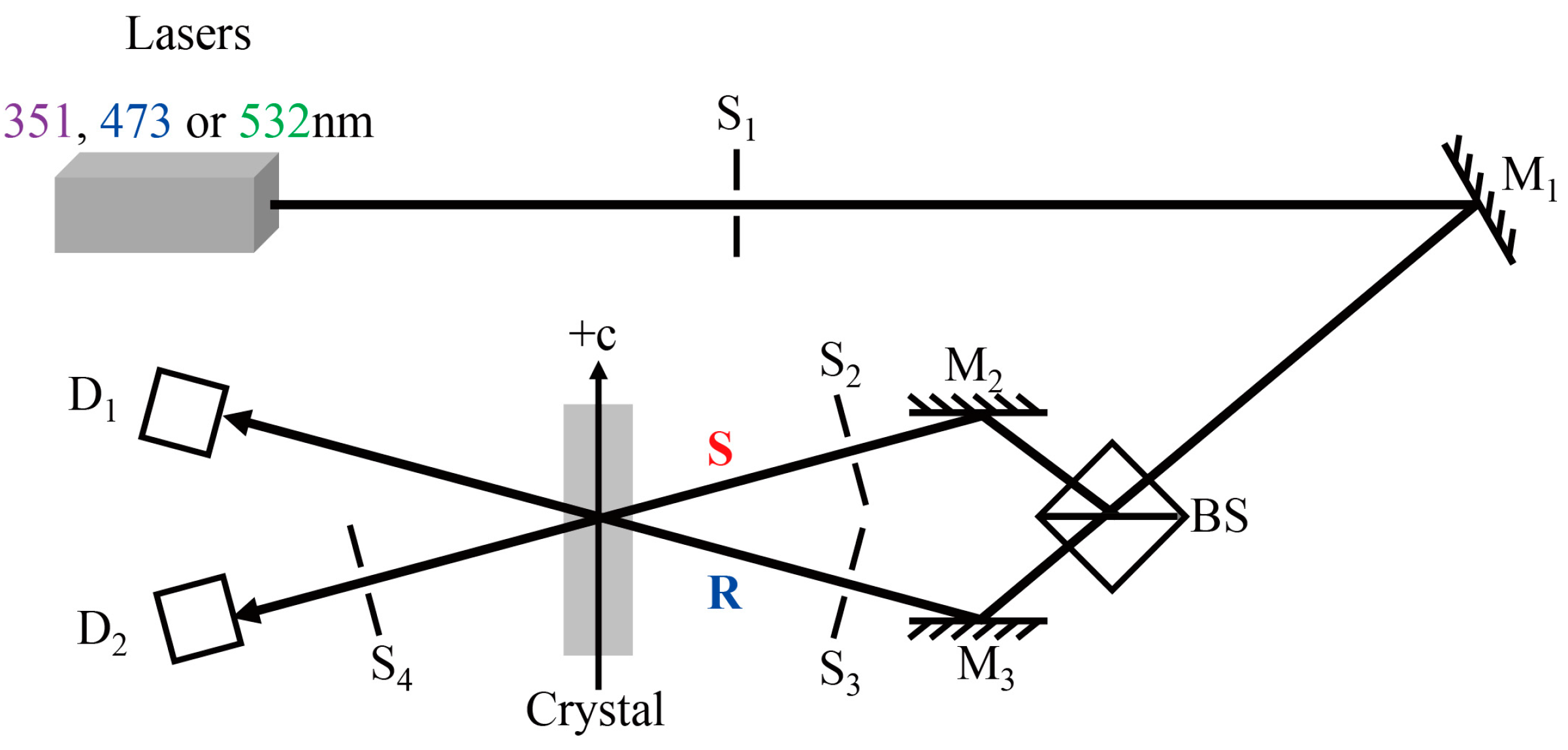
2. Materials and Methods

For the present investigation, a series of pure congruent LiNbO3 crystals (CLN) with 15 mm in diameter and 6 cm in length were grown along the c axis through the conventional Czochralski method. The [Li]/[Nb] composition was chosen as 48.38/51.62. The as-grown crystals were artificially poled using two different polarization methods to obtain a single domain state. Four of them were directly polarized in the growth furnace at the end of the growth process. The electrodes were added to the seed crystal rod and to the bottom of the crucible. During the crystal polarization, the temperature was maintained at 1200 °C and the polarized electric currents were chosen as 15 mA, 40 mA, 70 mA and 100 mA, labeled as CLN15, CLN40, CLN70, and CLN100, respectively. The number in the subscript represents the polarization current. Finally, these crystals were annealed at 1150 °C for 10 h in ambient atmosphere. However, another crystal was firstly extracted from the growth furnace and annealed at 1150 °C for 10 h in ambient atmosphere. It was put into a polarization furnace which was heated from room temperature to 1200 °C and artificially poled under the electric current of 40 mA, and labeled as CLN0 (here, “0” means the crystal was not directly polarized in the growth furnace). This is the normal process for polarizing LN crystals. The cross-section of the diameter part is about 7 cm2. The +c and −c direction of crystals and the single domain state can be easily determined by the piezoelectric effect. After confirming the crystals possessed the single domain state, 3.0 mm and 1.0 mm thick y-oriented plates were cut and polished to optical grade.
Holographic characteristics of these samples in the UV-visible range were investigated by two-wave mixing in transmission geometry at the wavelength of 351, 473 and 532 nm provided by an Ar+ laser and continuous wave frequency-doubled solid-state lasers, respectively [24,25]. The experimental setup is illustrated schematically in Figure 1. An extraordinarily polarized laser beam was split into two beams of equal intensity (with intensity per beam being 320, 400 and 400 mW/cm2, respectively), and formed object beam (S beam) and reference beam (R beam). The two beams had the same diameter of 1.5 mm. S beam located in the +c direction and R in the opposite direction of CLN crystals. Two mutually coherent beams irradiated these 3.0 mm thick plates with a crossing angle of 30°. The grating vector was aligned along the c-axis to exploit the largest electro-optic coefficient r33. In the measurement, S and R beam interfere in the crystals and record the phase gratings. When reaching the saturated diffraction efficiency of the grating, blocking S beam and erasing the gratings by R beam. The diffraction efficiency is defined here as Equation (1)
η = Id/(Id + It),
where Id and Id are the diffracted and transmitted intensity of the readout beam, respectively. The photorefractive response time constant τr and the saturation diffraction efficiency ηs are deduced by fitting the following function to the data (Equation (2)):
η(t) = ηs [1−exp(−t/τr)]2
The dominant carrier type in LiNbO3 crystals could be confirmed by light amplification, and the experimental setup was the same as the holographic experiment. The laser light was split into two beams, which would be reflected by two reflectors and formed signal beam (S beam) and reference beam (R beam). The ratio between the transmitted light power of the S and R beams was set as 1:150. During the recording of the phase grating, if there is a stable energy transfer between the two beams, it indicates that the diffusion effect dominates the photorefraction process. The light energy transfer toward −c axis means the dominant carriers are electrons, while the light energy transfer toward +c axis for holes.
The optical absorption spectra of our crystals were measured at room temperature by a Beckman DU-8B spectrophotometer (Beckman-Coulter, Brea, CA, USA) with light transmitting through 1.0 mm thick y-plates. The scanning step and speed were fixed to 0.5 nm and 150 nm/min, respectively. We obtained the absorption change by subtracting the measured light absorption of CLN0 from that of CLN that was polarized under different currents (it is helpful to get more information about the defects and avoid some optical phenomenon, such as the Fabry–Perot interference, disturbing the analysis and discussions). It should be mentioned that different positions in each sample were chosen for the measurements to ensure the reproducibility of the experimental data.

3. Results and Discussion

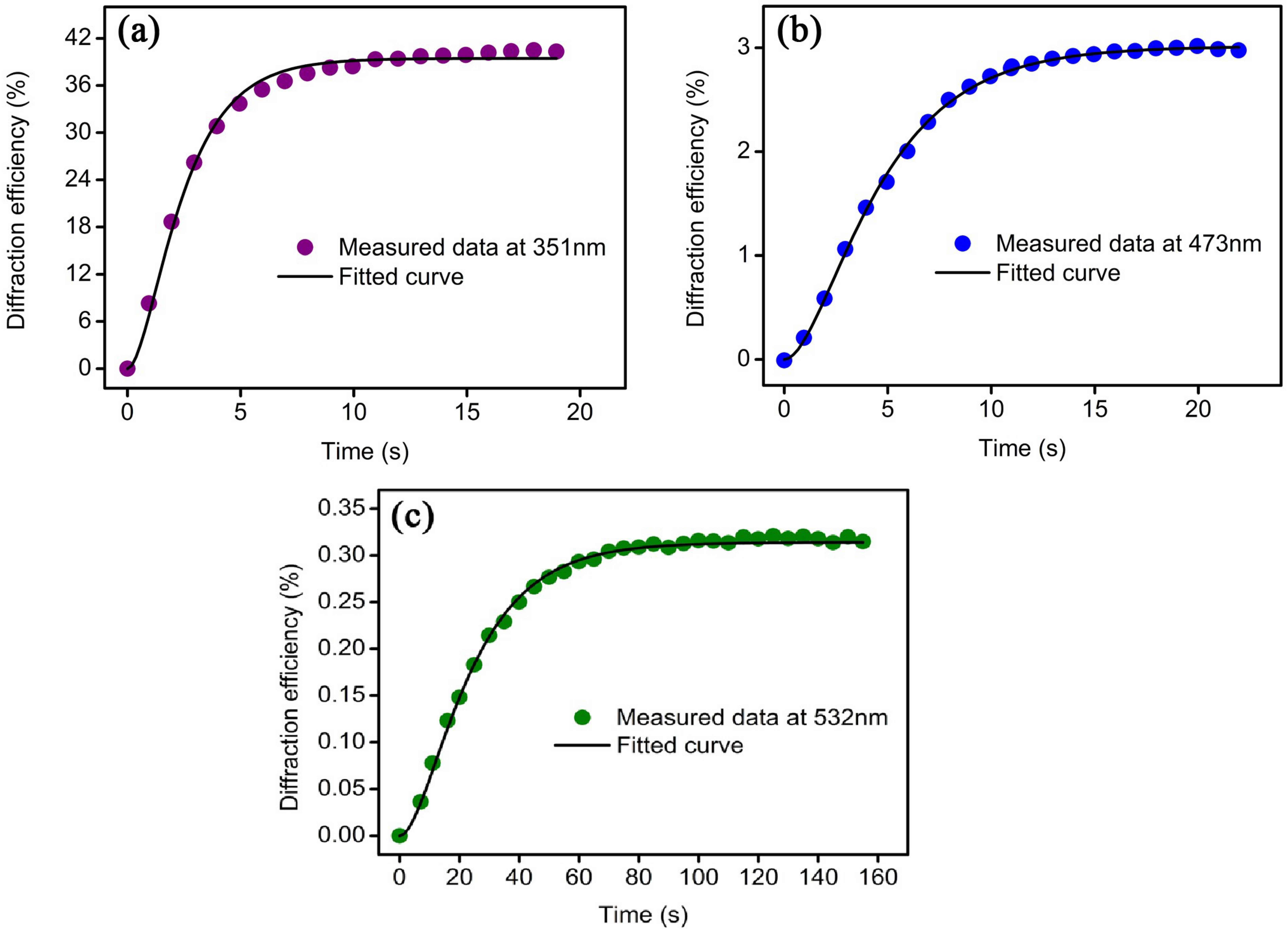
3.1. Photorefractive Response Time and Diffraction Efficiency

The typical curves of the diffraction efficiency as a function of time are shown in Figure 2, for CLN100, at the wavelengths of 351 nm (Figure 2a), 473 nm (Figure 2b) and 532 nm (Figure 2c). The relationships between the photorefractive properties of each CLN samples and polarization currents are shown in Figure 3. For comparison, the data for CLN0 are also presented. Holographic writing was achieved from UV to the visible for all CLN samples. We can see the evident influence of polarization current on the response time and diffraction efficiency. The response time was shortened, and the diffraction efficiency increased when the electric current was increased from 15 to 100 mA. The same variation tendency was observed as the wavelength varies from 532 to 351 nm. Especially, when the polarization current was enhanced to 100 mA, CLN maintained the short response time of 1.4 s at 351 nm, which was about one order of magnitude shorter as compared with CLN0 and some CLN crystals reported in other studies, and close to that of LN doped with 5 mol % Mg [26,27]. Meanwhile, CLN100 had a higher diffraction efficiency of 40.8% at 351 nm, which was about one or two orders of magnitude higher than some reported CLN crystals or CLN0, and even higher than that of LN doped with 5 mol % Mg at 351 nm [27]. Moreover, the response time of CLN100 decreased to only 3.8 s at 473 nm. This was approximately one order of magnitude shorter than that of CLN0 and very close to that of LN:Fe,Zr crystals, which were reported to be the fastest co-doped LN:Fe crystals in the visible range [28].

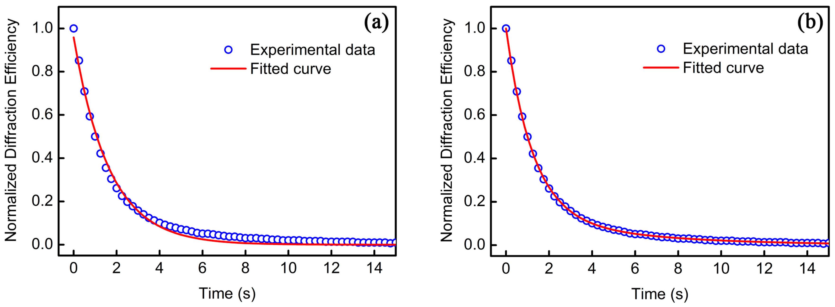
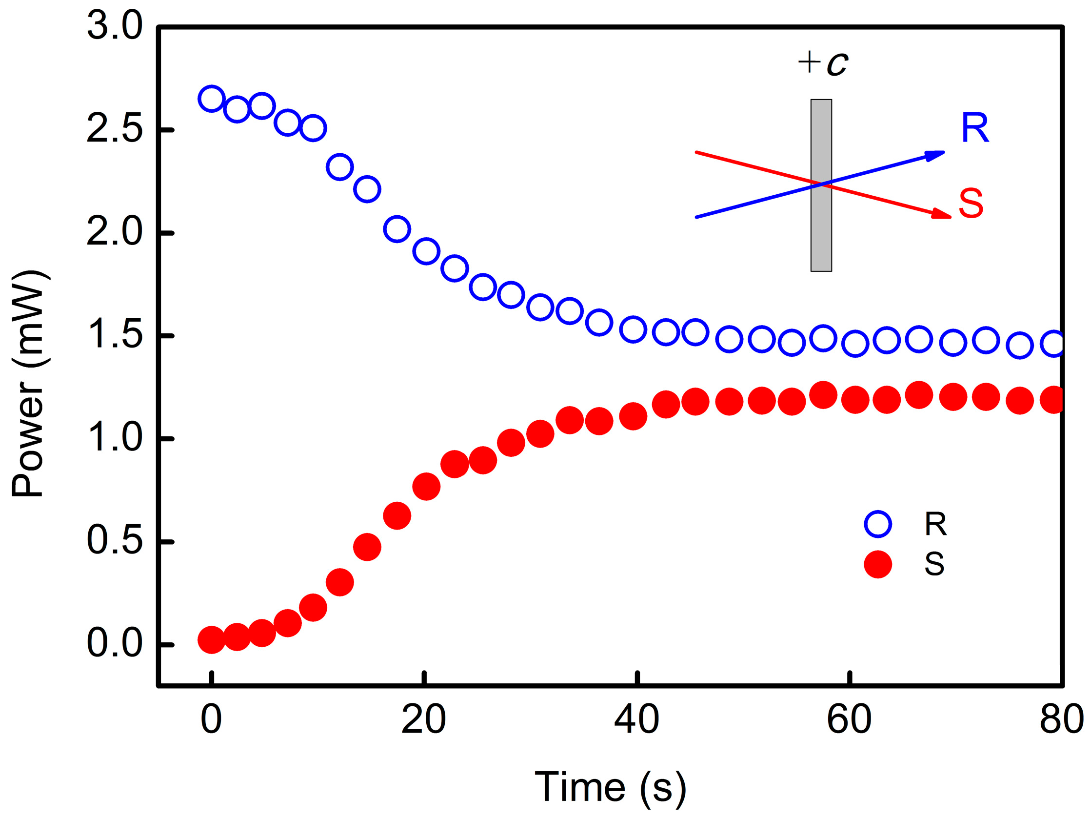
3.2. Light Erasing Behavior and Amplification

The improvement of the response speed and diffraction efficiency must have a crucial relationship with the photorefractive centers and the type of dominant carriers excited from these centers. To clarify the nature of the photorefractive centers in our crystals, we first investigated the light erasing behavior of photorefractive gratings in our samples. Here, we provide the normalized typical erasing curves of CLN100 at 351 nm as an example. The fitting results are shown in Figure 4 and listed in Table 1. The erasing curves exhibited large deviations when fitted by a mono-exponential function (Equation (3)):
η = η0 exp(−t/τ0)
but were modeled quite well by a sum of two exponentials (Equation (4)):
η = η1 exp(−t/τ1) + η2 exp(−t/τ2)
where η0 is the initial diffraction efficiency, η1,2 are two contributions to the diffraction efficiency, and τ0,1,2 is the time constant, respectively. This implies that at least two kinds of photorefractive centers are involved. Additionally, the light amplification experiment was employed to confirm the dominant carrier type in our samples. Here, we give the temporal evolution curves of CLN100 at 351 nm as an example (Figure 5). The transmitted light powers of S beam and R beam were set as 1:150. The evidenced steady-state energy transfer indicated that the diffusion effect dominated the UV photorefraction process [17,29], which is similar to the results of CLN crystals reported in other works (e.g., [25,30]). More importantly, the direction of energy transfer was toward to the −c end, which revealed that the sign of UV-excited carriers was negative and electrons were the dominant carriers. It should be mentioned that consistent results were obtained in our other samples.

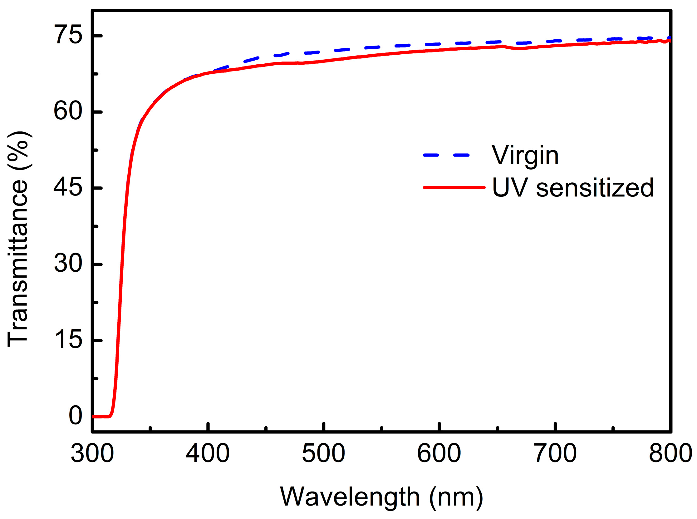
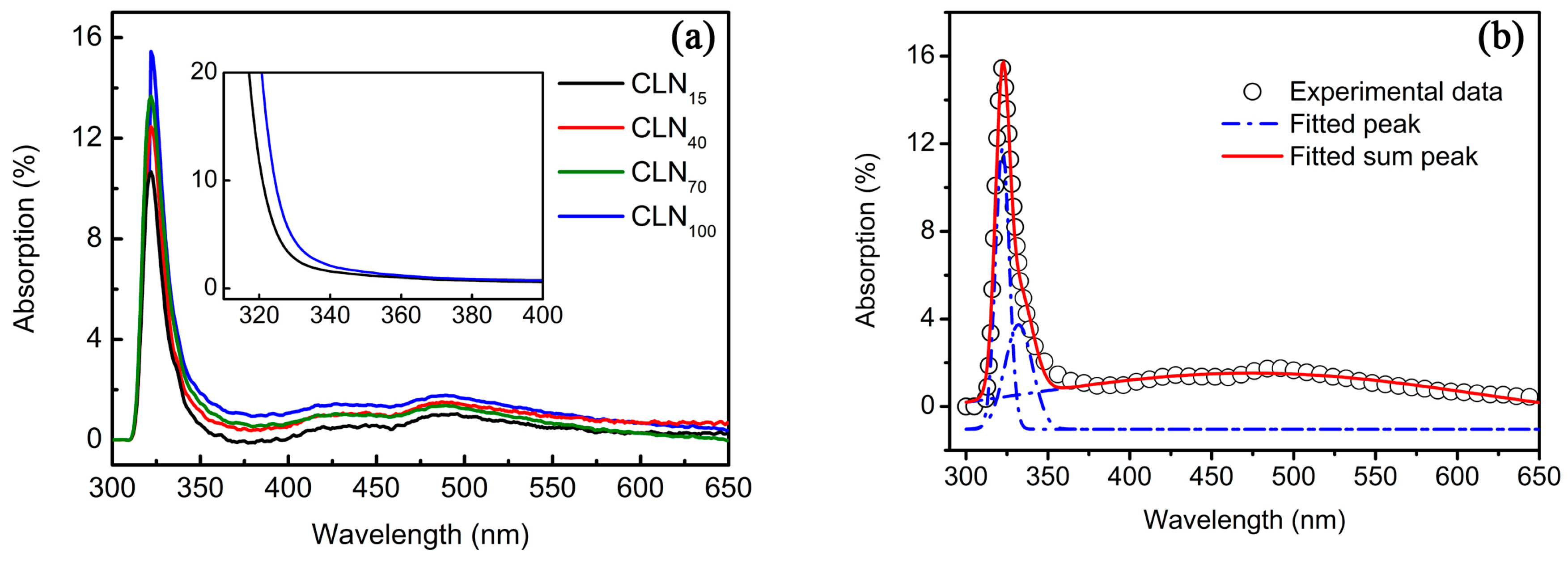
3.3. Absorption Spectra

It was also found that the color of CLN crystals varies with different polarization currents. Figure 6a shows the absorption difference between CLN polarized under various current relative to CLN0. A pronounced absorption peak in the UV region and a wide absorption peak in the visible region were observed for CLN polarized in the growth furnace. The wide range of the continuous absorption spectrum indicates that charge carriers can be excited from different energy levels at various wavelengths. This is essential for realizing holographic writing and erasing at different wavelengths. The absorption band is similar to that of reduced CLN crystals [22]. Figure 6a also indicates that increasing polarization current has the effect of reduction. This can be explained as follows. According to the literature of Bhatt et al. [31], the loss of oxygen (reduction) with releasing electrons was facilitated by the polarization process that was performed at very high temperature. As described in the former part, the four CLN crystals polarized in the growth furnace were maintained for much longer time at higher temperature than CLN0. Therefore, in the four CLN crystals, there could be more oxygen vacancy than CLN0. The oxygen vacancy carrying two positive charges can bind electrons, but more bound electrons can be activated to become free electrons with the improvement of the electric current and trapped by intrinsic defects, resulting in stronger absorption in the visible range [31,32].
Figure 6b gives the absorption spectra of CLN100 crystal fitted by a sum of Lorentz functions. The experimental data were fitted well and the spectra consist of three peaks centered at about 322, 332 and 474 nm. For CLN crystals, it is well known that different intrinsic defects or clusters play the role of photorefractive centers, from which carriers can be excited by light with different wavelengths. As electrons are the dominant carriers in our samples, intrinsic defects or clusters that can serve electrons to the conduction band may be considered photorefractive centers. As described in the Introduction, based on Li-vacancy model, the main intrinsic defects of CLN are Li vacancies (VLi) and anti-site Nb5+ (NbLi5+). Meanwhile, Small polarons (NbLi4+) are formed by electrons trapped at anti-site NbLi5+; bipolarons (NbLi4+-NbNb4+) are composed of a pair of electrons trapped at adjacent NbLi5+ and NbNb5+ [19]; and Q polarons can be considered a combination of two equivalent bipolarons [20,21,22]. The UV absorption edge of CLN has also been attributed to the presence of Li vacancies—actually of O2− ions, in the vicinity of VLi [33]. The UV absorption edge will red shift if more VLi are generated. As can be seen from the inset in Figure 6a, the UV absorption edge of CLN100 is red-shifted 2 nm compared to CLN0, which means more VLi are formed in CLN100. This is also in agreement with the findings reported by Hessenlink that more VLi was generated during reduction process in CLN [3]. It is universally acknowledged that O2−/− near VLi− (O2−/−–VLi) can serve as the UV photorefractive center in CLN. Because the UV peak at 322 nm is near the UV absorption edge of CLN, it should be correlated with the O2−/−–VLi defect. Akhmadullin et al. and Yan et al. [20,21,22] reported that Q polarons can be formed in reduced CLN and serves as photorefractive centers. More importantly, Q polarons are responsible for the absorption band at about 3.5 eV. Thus, Q polarons are highly likely to be the origin of the 332 nm peak in our case and also considered to be another UV photorefractive center. It was reported that the energy levels of bipolaron was approximately 2.5 eV and induced a wide absorption band in reduced CLN crystals [19,20,21]. As our samples were reduced under the polarization in the growth furnace and the wide absorption band at 474 nm was similar to the reported results, it could be attributed to bipolarons. Small polarons whose energy level is about 1.6 eV might also form in our samples, but it corresponds to the absorption band at about 780 nm, which can be observed only at temperatures below 80 K [34] .
In addition, an A400 mercury lamp with wavelengths centered at 365 nm was employed to sensitize CLN100 sample. The UV light intensity was 500 mW/cm2 and the irradiation time was 1 h. The transmittance spectrum of CLN100 in its virgin status and after sensitization is shown in Figure 7. It is clearly seen that a wide weak absorption band centered at about 470 nm appears when CLN100 was sensitized. The same phenomena were also found for other samples though not as apparently as for CLN100 because higher polarization current caused stronger reduction. Due to the strong reduction, most anti-site NbLi5+ and small polarons have been reduced to bipolarons and Q polarons in CLN100. As reported in [22], it is reasonable to deduce that the filled Q polarons in the reduced CLN may be excited by UV illumination with low light intensity and dissociated into bipolarons. However, most of these bipolarons capture electrons and combine to become new Q polarons immediately. As a result, a wide absorption band with a weak intensity appears in CLN100 after sensitization.
Based on the aforementioned results, we can give a description of one possible mechanism for the remarkable improvement in the photorefractive response speed and diffraction efficiency of CLN crystals polarized in the growth furnace, especially in CLN100. Compared to CLN0 crystal, being maintained at high temperature for longer time and higher polarization current causes more O2−/−–VLi and anti-site NbLi5+, thus small polarons are reduced to bipolarons and Q polarons. Under the UV light illumination, several electrons are excited from the donors of O2−–VLi and Q polarons to conduction band. Although Q polarons dissociated into bipolarons, most of these bipolarons immediately captured electrons and combined to become new Q polarons. It is easy to form space-charge field and consequently lead to a fast response time. It is a remarkable fact for our samples that bipolarons are the electron acceptors but do not play the role of trapper to reduce the response speed in doped LN crystals. Therefore, the response speed of CLN100 in UV region is improved, and the diffraction efficiency was enhanced due to the concentration increment of donors. Although few small polarons may still exist in CLN100, their lifetimes are sharply shortened because electrons prefer to be captured by abundant Q polarons and bipolarons, which have deep energy levels and have a role of shortening small polarons lifetime [22]. This might be the reason for CLN100 also obtaining fast response speed at 473 nm relative to CLN0. For CLN100 crystal, the wide but not strong absorption region in the visible region means more bipolarons can serve as donors at 473 nm, resulting in slight enhancement of diffraction efficiency. This explanation must, however, be substantiated by more detailed investigations, such as the thermal effect of UV-light-induced absorption and its decay behavior in our samples, which are currently underway in our laboratory.

4. Conclusions

In summary, a series of CLN crystals were grown and directly polarized under different electric currents in the growth furnace. Holographic recording was achieved from UV to the visible for all CLN samples. The response time shortened, whereas the diffraction efficiency increased incrementally with the electric current. CLN100 maintained the short response time of 1.4 s and high diffraction efficiency of 40.8% at 351 nm, which is close to and higher than that of LN doped with 5 mol % Mg, respectively. Moreover, the response time of CLN100 is shortened to 3.8 s at 473 nm and 16.9 s at 532 nm. The light erasing behavior implies that at least two kinds of photorefractive centers exist in the crystals. The domination of the photorefraction process and carriers are diffusion effect and electrons. Increment of polarization current induces a pronounced UV absorption peak and a wide visible absorption peak in CLN crystals, which are correlated with O2−/−–VLi, bipolarons and Q polarons. The improvement of response speed is attributed to the combined effect of these intrinsic defects. The experimental results indicated that increasing the polarization electric current is an effect method to improve the photorefractive response of LN crystal.

Acknowledgments

This work was partially supported by the National Natural Science Foundation of China (61605116, 61705116 and 51572175), Shanghai Innovation action plan project (15520503400), and Jiangsu Planned Projects for Postdoctoral Research Funds (1501131C).

Author Contributions

Tian Tian and Yongfa Kong conceived and designed the experiments. Tian Tian and Xiaodong Yan performed the experiments and analyzed the data. Hongde Liu, Dahuai Zheng, Shiguo Liu and Shaolin Chen contributed the measurements. Jingjun Xu and Jiayue Xu contributed the useful and deep discussions. Tian Tian wrote the manuscript. All authors read and approved the final version of the manuscript to be submitted.

Conflicts of Interest

The authors declare no conflict of interest.

References

  1. Räuber, A. Current Topics in Materials Science; Kaldis, E., Ed.; North Holland Publishing Company: Amsterdam, The Netherlands, 1978; Volume 1. [Google Scholar]
  2. Günter, P.; Huignard, J.P. Photorefractive materials and their applications vols I and II (Heidelberg: Springer). Top. Appl. Phys. 1989. [Google Scholar] [CrossRef]
  3. Hesselink, L.; Orlov, S.S.; Liu, A.; Akella, A.; Lande, D.; Neurgaonkar, R.R. Photorefractive materials for nonvolatile volume holographic data storage. Science 1998, 282, 1089–1094. [Google Scholar] [CrossRef] [PubMed]
  4. Tay, S.; Blanche, P.A.; Voorakaranam, R.; Tunç, A.V.; Lin, W.; Rokutanda, S.; Gu, T.; Flores, D.; Wang, P.; Li, G.; et al. An updatable holographic three-dimensional display. Nature 2008, 451, 694–698. [Google Scholar] [CrossRef] [PubMed]
  5. Blanche, P.A.; Bablumian, A.; Voorakaranam, R.; Christenson, C.; Lin, W.; Gu, T.; Flores, D.; Wang, P.; Hsieh, W.Y.; Kathaperumal, M.; et al. Holographic three-dimensional telepresence using large-area photorefractive polymer. Nature 2010, 468, 80–83. [Google Scholar] [CrossRef] [PubMed]
  6. Köber, S.; Salvador, M.; Meerholz, K. Organic photorefractive materials and applications. Adv. Mater. 2011, 23, 4725–4763. [Google Scholar] [CrossRef]
  7. Tsutsumi, N.; Kinashi, K.; Sakai, W.; Nishide, J.; Kawabe, Y.; Sasabe, H. Real-timethree-dimensional holographic display using a monolithic organic compound dispersed film. Opt. Mater. Express 2012, 2, 1003–1010. [Google Scholar] [CrossRef]
  8. Tsutsumi, N.; Kinashi, K.; Tada, K.; Fukuzawa, K.; Kawabe, Y. Fully updatable three-dimensional holographic stereogram display device based on organic monolithic compound. Opt. Express 2013, 21, 19880–19884. [Google Scholar] [CrossRef] [PubMed]
  9. Giang, H.N.; Kinashi, K.; Sakai, W.; Tsutsumi, N. Photorefractive response and real-time holographic application of a poly(4-(diphenylamino)benzylacrylate)-based composite. Polym. J. 2013, 46, 59–66. [Google Scholar] [CrossRef]
  10. Sasaki, T.; Ikegami, M.; Abe, T.; Miyazaki, D.; Kajikawa, S.; Naka, Y. Real-timedynamic hologram in photorefractive ferroelectric liquid crystal with two-beam coupling gain coefficient of over 800 cm−1 and response time of 8 ms. Appl. Phys. Lett. 2013, 102, 063306. [Google Scholar] [CrossRef]
  11. Broderick, N. Lithium Niobate. Nature Materials Update. 2002. Available online: http://www.nature.com/materials/news/features/021107/portal/m021031-6.html (accessed on 20 September 2017).
  12. Papazoglou, D.G.; Loulakis, M.; Siganakis, G.; Vainos, N.A. Holographic read-write projector of video images. Opt. Express 2002, 10, 280–285. [Google Scholar] [CrossRef] [PubMed]
  13. Shin, S.H.; Javidi, B. Speckle-reduced three-dimensional volume holographic display by use of integral imaging. Appl. Opt. 2002, 41, 2644–2649. [Google Scholar] [CrossRef] [PubMed]
  14. Kong, Y.F.; Liu, S.G.; Xu, J.J. Recent advances in the photorefraction of doped lithium niobate crystals. Materials 2012, 5, 1954–1971. [Google Scholar] [CrossRef]
  15. Phillips, W.; Amodei, J.J.; Staebler, D.L. Optical and holographic storage properties of transition metal doped lithium niobate. RCA Rev. 1972, 33, 94–109. [Google Scholar]
  16. McMillen, D.K.; Hudson, T.D.; Wagner, J.; Singleton, J. Holographic recording in specially doped lithium niobate crystals. Opt. Express 1998, 2, 491–502. [Google Scholar] [CrossRef] [PubMed]
  17. Dong, Y.F.; Liu, S.G.; Kong, Y.F.; Chen, S.L.; Rupp, R.; Xu, J.J. Fast photorefractive response of vanadium-doped lithium niobate in the visible region. Opt. Lett. 2012, 37, 1841–1843. [Google Scholar] [CrossRef] [PubMed]
  18. Tian, T.; Kong, Y.F.; Liu, S.G.; Li, W.; Wu, L.; Chen, S.L.; Xu, J.J. Photorefraction of molybdenum-doped lithium niobate crystals. Opt. Lett. 2012, 37, 2679–2681. [Google Scholar] [CrossRef] [PubMed]
  19. Schirmer, O.F.; Thiemann, O.; Wöehlecke, M. Defects in LiNbO3. I. Experimental aspects. J. Phys. Chem. Solids 1991, 52, 185–200. [Google Scholar] [CrossRef]
  20. Akhmadullin, I.S.; Golenishchev-Kutuzov, V.A.; Migachev, S.A. Electronic structure of deep centers in LiNbO3. Phys. Solid State 1998, 40, 1012–1018. [Google Scholar] [CrossRef]
  21. Yan, W.B.; Kong, Y.F.; Shi, L.H.; Sun, L.; Liu, H.D.; Li, X.C.; Zhao, D.; Xu, J.J.; Chen, S.L.; Zhang, L.; et al. Influence of composition on the photorefractive centers in pure LiNbO3 at low light intensity. Appl. Opt. 2006, 45, 2453–2458. [Google Scholar] [CrossRef] [PubMed]
  22. Yan, W.B.; Shi, L.H.; Chen, H.J.; Li, Y.X.; Kong, Y.F. The UV-light-induced absorption in pure LiNbO3 investigated by varying compositions. J. Phys. D Appl. Phys. 2008, 41, 085410. [Google Scholar] [CrossRef]
  23. Lüdtke, F.; Waasem, N.; Buse, K.; Sturman, B. Light-induced charge-transport in undoped LiNbO3 crystals. Appl. Phys. B 2011, 105, 35–50. [Google Scholar] [CrossRef]
  24. Pei, Z.; Hu, Q.; Kong, Y.F.; Liu, S.G.; Chen, S.L.; Xu, J.J. Investigation on p-type lithium niobate crystals. AIP Adv. 2011, 1, 032171. [Google Scholar] [CrossRef]
  25. Tian, T.; Kong, Y.F.; Liu, H.D.; Liu, S.G.; Li, W.; Chen, S.L.; Xu, J.J.; Xu, J.Y.; Zeng, H.B. Fabrication and formation mechanism of p-type lithium niobate crystals by molybdenum doping and polarization. J. Mater. Sci. Mater. Electron. 2016, 27, 5886–5891. [Google Scholar] [CrossRef]
  26. Jungen, R.; Angelow, G.; Laeri, F.; Grabmaier, C. Efficient ultraviolet photorefraction in LiNbO3. Appl. Phys. A 1992, 55, 101–103. [Google Scholar] [CrossRef]
  27. Xu, J.J.; Zhang, G.Y.; Li, F.F.; Zhang, X.Z.; Sun, Q.; Liu, S.M.; Song, F.; Kong, Y.F.; Chen, X.J.; Qiao, H.J.; et al. Enhancement of ultraviolet photorefraction in highly magnesium-doped lithium niobate crystals. Opt. Lett. 2000, 25, 129–131. [Google Scholar] [CrossRef] [PubMed]
  28. Kong, Y.F.; Wu, S.Q.; Liu, S.G.; Chen, S.L.; Xu, J.J. Fast photorefractive response and high sensitivity of Zr and Fe codoped LiNbO3 crystals. Appl. Phys. Lett. 2008, 92, 251107. [Google Scholar] [CrossRef]
  29. Yan, W.B.; Shi, L.H.; Chen, H.J.; Zhang, X.Z.; Kong, Y.F. Investigations on the UV photorefractivity of LiNbO3:Hf. Opt. Lett. 2010, 35, 601–603. [Google Scholar] [CrossRef] [PubMed]
  30. Staebler, D.L.; Amodei, J.J. Coupled-wave analysis of holographic storage in LiNbO3. J. Appl. Phys. 1972, 43, 1042–1049. [Google Scholar] [CrossRef]
  31. Bhatt, R.; Bhaumik, I.; Ganesamoorthy, S.; Bright, R.; Soharab, M.; Karnal, A.K.; Gupta, P.K. Control of intrinsic defects in lithium niobate single crystal for optoelectronic applications. Crystals 2017, 7, 23. [Google Scholar] [CrossRef]
  32. Zhao, H.Q.; Wang, J.O.; Zhang, L.X.; Rong, Y.C.; Chen, J.; Ibrahim, K.; Xing, X.R. Effects of oxygen vacancy on the electronic structure and multiferroics in sol–gel derived Pb0.8Co0.2TiO3 thin films. Dalton Trans. 2013, 42, 10358–10364. [Google Scholar] [CrossRef] [PubMed]
  33. Li, X.C.; Kong, Y.F.; Liu, H.D.; Sun, L.; Xu, J.J.; Chen, S.L.; Zhang, L.; Huang, Z.H.; Liu, S.G.; Zhang, G.Y. Origin of the generally defined absorption edge of non-stoichiometric lithium niobate crystals. Solid State Commun. 2007, 141, 113–116. [Google Scholar] [CrossRef]
  34. Ketchum, J.L.; Sweeney, K.L.; Halliburton, L.E.; Armington, A.F. Vacuum annealing effects in lithium niobate. Phys. Lett. A 1983, 94, 450–453. [Google Scholar] [CrossRef]
Figure 1. Schematic diagram of the configuration for holographic experiment: M1–M3, mirrors; BS, beam splitter; S1–S4, shutters; D1–D2, detectors.
Crystals 07 00368 g001
Figure 2. The measured diffraction efficiency as a function of time for CLN100 measured at various wavelengths: (a) 351 nm; (b) 473 nm; and (c) 532 nm.
Crystals 07 00368 g002
Figure 3. The UV-visible photorefractive (a) diffraction efficiency and (b) response time of CLN crystals polarized under various polarization currents. The light intensity per beam is 320, 400 and 400 mW/cm2 for 351, 473 and 532 nm laser, respectively.
Crystals 07 00368 g003
Figure 4. The normalized erasing curves of CLN100 at 351 nm: (a,b) curves fitted by mono-exponential function and double-exponential functions, respectively. The circles represent experimental data and the solid are fitted curves.
Crystals 07 00368 g004
Figure 5. The temporal evolution of light amplification in CLN100 with the initial power ratio of the transmitted S and R beams of 1:150.
Crystals 07 00368 g005
Figure 6. (a) The absorption difference of CLN polarized under various currents relative to CLN0, where the inset is the absorption coefficient of CLN0 and CLN100. (b) The fitted curve of CLN100, where the circles represent experimental data and the solid lines are fitted curves; the fitting peaks are centered at about 322, 332, and 474 nm, respectively.
Crystals 07 00368 g006
Figure 7. Transmittance of CLN100 before and after sensitization by an A400 mercury lamp with wavelengths centered at 365 nm.
Crystals 07 00368 g007
Table 1. Fitting parameters of the normalized erasing curves for CLN100 at 351 nm.
One-CenterTwo-Center
η0τ0 (s)η1τ1 (s)η2τ2 (s)
0.96 ± 0.0061.65 ± 0.0140.86 ± 0.0031.23 ± 0.0050.14 ± 0.0055.28 ± 0.006

